

Page 1

User Manual
Motion Analyzer Software
Version 7.00
Page 2

Important User Information
IMPORTANT
Solid-state equipment has operational characteristics differing from those of electromechanical equipment. Safety
Guidelines for the Application, Installation and Maintenance of Solid State Controls (publication SGI-1.1
your local Rockwell Automation® sales office or online at http://www.rockwellautomation.com/literature/
important differences between solid-state equipment and hard-wired electromechanical devices. Because of this difference,
and also because of the wide variety of uses for solid-state equipment, all persons responsible for applying this equipment
must satisfy themselves that each intended application of this equipment is acceptable.
In no event will Rockwell Automation, Inc. be responsible or liable for indirect or consequential damages resulting from the
use or application of this equipment.
The examples and diagrams in this manual are included solely for illustrative purposes. Because of the many variables and
requirements associated with any particular installation, Rockwell Automation, Inc. cannot assume responsibility or
liability for actual use based on the examples and diagrams.
No patent liability is assumed by Rockwell Automation, Inc. with respect to use of information, circuits, equipment, or
software described in this manual.
Reproduction of the contents of this manual, in whole or in part, without written permission of Rockwell Automation,
Inc., is prohibited.
Throughout this manual, when necessary, we use notes to make you aware of safety considerations.
available from
) describes some
WARNING: Identifies information about practices or circumstances that can cause an explosion in a hazardous environment,
which may lead to personal injury or death, property damage, or economic loss.
ATTENTION: Identifies information about practices or circumstances that can lead to personal injury or death, property
damage, or economic loss. Attentions help you identify a hazard, avoid a hazard, and recognize the consequence.
SHOCK HAZARD: Labels may be on or inside the equipment, for example, a drive or motor, to alert people that dangerous
voltage may be present.
BURN HAZARD: Labels may be on or inside the equipment, for example, a drive or motor, to alert people that surfaces may
reach dangerous temperatures.
Identifies information that is critical for successful application and understanding of the product.
Allen-Bradley, Kinetix, MP-Series, ProposalWorks, Rockwell Automation, Rockwell Software, RSLogix, TechConnect, TL-Series, and Ultra are trademarks of Rockwell Automation, Inc.
Trademarks not belonging to Rockwell Automation are property of their respective companies.
Page 3

This manual contains new and updated information.
Summary of Changes
New and Updated Information
This table contains the changes made to this revision.
Top ic Pa ge
Removed the Activation Wizard section. N/A
Added Group/Ungroup and Add Drive Group descriptions to the Home Tab section. 16
Updated Power Data, Shunt, and Energy tab examples for the
Power Supply/Accessories - Single-axis Drive Systems section.
Added Power Supply/Accessories – AC/DC Power Sharing Systems (Kinetix 5500 drives) section. 51
Updated the Output Format Selection dialog boxes in the Export to RSLogix 5000 Wizard section. 65
Added new Explorer View examples and updated the Drives Group Node description. 78
Updated the Solution List dialog box example. 209
Added Preferred Product section. 210
46
Rockwell Automation Publication MOTION-UM004B-EN-P - October 2012 3
Page 4

Summary of Changes
Notes:
4 Rockwell Automation Publication MOTION-UM004B-EN-P - October 2012
Page 5

Preface
About This Publication
Who Should Use This Manual
Conventions Used in This Manual
System Requirements
The versatility of Motion Analyzer software lets users of various application
complexities and experience levels use one software package to size their systems.
This manual is designed to accommodate basic users, advanced users, and
everyone in between.
This manual is intended for engineers directly involved in the selecting, sizing,
and optimizing of drives and motors or actuators for a motion control system.
The following conventions are used throughout this manual:
• Bulleted lists such as this one provide information, not procedural steps.
• Numbered lists provide sequential steps or hierarchical information.
• Hyperlinks are embedded throughout this document so that you can easily
navigate to and obtain information that is relevant to your particular
application.
Motion Analyzer software requires the following operating conditions.
Attribute Description
Compute r hardware requ irements
Operating systems supported
Microsoft Office software supported
• Pentium IV processor
• 1 GB RAM minimum
• 1280x800 screen resolution
• Windows XP - 32 Bit (SP2)
• Windows XP - 64 Bit (SP2)
• Windows Vista - 32 Bit
• Office 2007
• Office 2010
• 500 MB free space in the
installation directory
• .NET Framework 2.0
• Windows Vista - 64 Bit
• Windows 7 - 32 Bit
• Windows 7 - 64 Bit
Additional Resources
These documents contain additional information concerning related products
from Rockwell Automation.
Resource Description
Download Motion Analyzer software from:
http://www.ab.rockwellautomation.com/motion-control/motion-analyzer-software
Kinetix Motion Control Selection Guide, publication GMC-SG001
Industrial Automation Wiring and Grounding Guidelines, publication 1770-4.1 Provides general guidelines for installing a Rockwell Automation industrial system.
Product Certifications website, http://www.ab.com
Comprehensive motion application sizing tool used for analysis, optimization,
selection, and validation of your Kinetix® Motion Control system.
Overview of Kinetix servo drives, motors, actuators, and motion accessories designed to
help make initial decisions for the motion control products best suited for your system
requirements.
Provides declarations of conformity, certificates, and other certification details.
You can view or download publications at
http:/www.rockwellautomation.com/literature/
. To order paper copies of
technical documentation, contact your local Allen-Bradley® distributor or
Rockwell Automation sales representative.
Rockwell Automation Publication MOTION-UM004B-EN-P - October 2012 5
Page 6

Preface
Notes:
6 Rockwell Automation Publication MOTION-UM004B-EN-P - October 2012
Page 7

Welcome to Motion Analyzer Software
Top ic Pa ge
Before You Begin Sizing 8
Database Updater Program 8
Welcome to Motion Analyzer 13
Menu Bar and Quick Access Toolbar 14
File Tab 15
Home Tab 16
Graphical View 17
Group View 22
Multiple Profile View 26
Power Supply/Accessories View 29
Preferences Tab 62
Export – Import Tab 65
Export to RSLogix 5000 Wizard 65
Bill of Materials (BOM) Tab 76
Help Tab 76
Explorer View 78
Chapter 1
Rockwell Automation Publication MOTION-UM004B-EN-P - October 2012 7
Page 8

Chapter 1 Welcome to Motion Analyzer Software
TIP
TIP
1.1. Before You Begin Sizing
After downloading and starting Motion Analyzer software, you’ll want to update
the Motion Analyzer database with the latest Allen-Bradley products available for
motion control applications. This section steps you through that process.
Download Motion Analyzer software from
http://www.ab.rockwellautomation.com/motion-control/motion-analyzer-software
.
1.1.1. Database Updater Program
The Motion Analyzer Database Updater program updates your Motion Analyzer
software with the latest database available for the version currently installed on
your personal computer.
1. To start the Motion Analyzer database updater program, go to
Start>All Programs>Rockwell Automation>Motion Analyzer 7.00>
Database Updater.
To update the software version, download Motion Analyzer software from
http://www.ab.rockwellautomation.com/motion-control/motion-analyzer-software
The Motion Analyzer Database Updater wizard opens.
.
Table 1 - Database Updater Analysis
Attribute Description
Installed Motion
Analyzer version
Installed database
version
Indicates the version of Motion Analyzer software currently installed.
Indicates the database version currently installed.
2. Click Next.
8 Rockwell Automation Publication MOTION-UM004B-EN-P - October 2012
Page 9

Welcome to Motion Analyzer Software Chapter 1
The program checks for database updates.
If the program finds that you already have the current database installed,
the following dialog box opens.
3. Click Finish.
Rockwell Automation Publication MOTION-UM004B-EN-P - October 2012 9
Page 10

Chapter 1 Welcome to Motion Analyzer Software
4. If the program finds that a database update is available, a dialog box opens
with the following information:
• Installed software and database versions
• Available database version
• Database download file size
• Summary of new features and products in the new database
5. Click Update.
10 Rockwell Automation Publication MOTION-UM004B-EN-P - October 2012
Page 11

Welcome to Motion Analyzer Software Chapter 1
6. If the database updater program detects that your current version of
Motion Analyzer software is running, a dialog box opens with the
following instructions.
7. If the program finds that a new software version is available, a dialog box
opens with the following options:
• Click the link to download the new version of Motion Analyzer
software
• Click Next to skip the download and just update your current database
Rockwell Automation Publication MOTION-UM004B-EN-P - October 2012 11
Page 12

Chapter 1 Welcome to Motion Analyzer Software
8. When the database updater program begins the update, this dialog box
opens.
9. When the database updater program completes the update, this dialog box
opens.
10. Click Finish.
12 Rockwell Automation Publication MOTION-UM004B-EN-P - October 2012
Page 13

Welcome to Motion Analyzer Software Chapter 1
1.1.2. Welcome to Motion Analyzer
The Welcome to Motion Analyzer dialog box opens when the software
application is launched. Two modes of operation are possible.
Figure 1 - Welcome to Motion Analyzer Dialog Box
Table 2 - Motion Analyzer Modes of Operation
Mode Description
Size and Select
Just Quote Creates only a bill of materials so no sizing input is required.
Intuitive workflow to help size, select, and optimize the motion control system. This mode also
creates a bill of materials.
Click either of the New option modes to start a new application or click Browse
to open a previously configured application.
Rockwell Automation Publication MOTION-UM004B-EN-P - October 2012 13
Page 14

Chapter 1 Welcome to Motion Analyzer Software
Menu Bar
Quick Access Toolbar
1.2. Menu Bar and Quick Access Toolbar
Your Motion Analyzer application file opens and the menu bar appears across the
top of the dialog box. Above the menu bar is the Quick Access toolbar.
Figure 2 - Size and Select Dialog Box
The Quick Access toolbar provides shortcuts to commonly used functions.
These functions include New, Open, Save, and Print.
Table 3 - Me nu Bar Ta b Descrip tion s
Options Description Page
File Tab
Home Tab
Preferences Tab Setting /View user preference option. 62
Export – Import Tab All data Export – Import functionality. 65
Bill of Materials (BOM) Tab
Help Tab Standard Help menu options. 76
Standard File menu options. 15
Most commonly used actions across different views in Motion Analyzer
software.
Useful shortcuts for navigating through the Bill of Materials view. 76
16
14 Rockwell Automation Publication MOTION-UM004B-EN-P - October 2012
Page 15

Welcome to Motion Analyzer Software Chapter 1
1.2.1. File Tab
The File tab is similar to the file menu in many computer applications.
Figure 3 - File Tab Options
Table 4 - File Tab Descriptions (refer to Figure 3
Options Description
New Click New to go to the Welcome dialog box in Motion Analyzer software.
Open
Save Click to save the running Motion Analyzer application. Standard Save functionality.
Save As
Recent Files
Sample Applications
Print
Help This is similar to the Help Tab
Exit Click to close the running application.
Click Open to browse folders and open Motion Analyzer applications. Standard Open
functionality.
Click to launch a dialog box, browse to the path on your computer, and save the current
application to an.mba file.
Click for the list of recently opened applications. You can open one of these applications
directly from this shortcut.
Lets you open Motion Analyzer sample applications present in the Motion Analyzer
installation.
Print Click to print the application data.
Print Preview Click to see a preview of printable application data.
)
on page 76.
Rockwell Automation Publication MOTION-UM004B-EN-P - October 2012 15
Page 16

Chapter 1 Welcome to Motion Analyzer Software
1.2.2. Home Tab
The Home tab contains five sections.
Figure 4 - Home Tab Options
Table 5 - Home Tab De scription s
Option Description
Used to access the different views available in Motion Analyzer software.
Click to open the Graphical view on page 17.
Click to open the Multiple Profile view on page 26.
Click to open the Power Supply/Accessories view on page 29.
Click to open the Axis view on page 82.
Click to open the BOM view on page 36.
Click to sort the axes in Drives group for Multi Axis Family application
by Axis Power. Sort is valid at the Rack, Group, or IPIM level.
Select multiple axes in Exp lorer view and clic k Group to create a Power
Sharing Drive Group. This feature is available only for families that
support AC and DC power sharing (Kinetix 5500 drives).
Select Power Sharing Drive Group in the Explorer view and click
Ungroup to ungroup the axes of the selected group.
Add a new IPIM module in the selected Drives Group in Explorer
hierarchy view.
Add a new axis in the Drives Group/Unallocated Group or IPIM based
on user’s current selection in Explorer hierarchy view.
Add a new Drives Group under the Project node in the Explorer
hierarchy view. This feature is available only for families that support
AC and DC sharing (Kinetix 5500 drives).
View s
(label 1 in Figure 4
Clipboard
(label 2 in Figure 4)
Edit
(label 3 in Figure 4
Add
(label 4 in Figure 4
Too l s
(label 5 in Figure 4
Graphical View
Group View Click to open the Group view on page 22.
Multiple Profile View
Power Supply/
)
Accessories View
Identify Your Load
Axis View
System Bill of
Materials (BOM) View
Used to access the Cut, Copy, and Paste functions. Click to perform these functions that are
common to many software programs.
Used to access these editing functions. Each one works on the entity selected in Explorer
hierarchy view.
Rename Click to rename the selected entity.
Delete Click to delete the selected entity from the ap plication.
Sort by Power
)
Allocate Allocate the axis from Un-allocate Axes Group to Drives Group.
Unallocate Un-allocate the axis from Drives Group to un-allocate Axes Group.
Group/Ungroup
Used to access these add functions. Each one works on the entity selected in Explorer hierarchy
view.
Add IPIM
)
Add Axis
Add Drive Group
Motion Analyzer/SolidWorks Integration is used to launch the SolidWorks Integration wizard.
)
16 Rockwell Automation Publication MOTION-UM004B-EN-P - October 2012
Page 17

Welcome to Motion Analyzer Software Chapter 1
1.2.2.1. Graphical View
The Graphical view applies to multi-axis drive families and provides graphical
representation of the current (Bulletin 2093 and 2094) power rail and
Kinetix 6000M integrated drive-motor system configurations.
Figure 5 - Graphical View Example
Table 6 - Graphical View Options (refer to Figure 5
Options Description Page
Power R ail View
Power Inte rface
Module View
Displays the graphical representation of the current Bulletin 2093 or 2094
power rail configuration.
Displays the graphical representation of the Kinetix 6000M integrated drivemotor system on the Bulletin 2094 power rail.
)
18
20
Rockwell Automation Publication MOTION-UM004B-EN-P - October 2012 17
Page 18

Chapter 1 Welcome to Motion Analyzer Software
1.2.2.1.1. Power Rail View
The Power Rail view displays the graphical representation of the current Bulletin
2093 or 2094 power rail configuration.
Figure 6 - Power Rail View Example
Table 7 - Power Rail View Options
Options Description
Product Rack
Summary
(label 1 in Figure 6
Image view
(label 2 in Figure 6
Module Information
(label 3 in Figure 6
Additional
Module Information
(inside red box)
Part Number Displays the selected power rail catalog number.
Total No. of Slots Displays the total number of slots available in the selected power rail.
)
Slots Occupied Displays the number of slots currently occupied in the selected power rail.
Graphical representation of the power rail with the drive modules and empty slots are
displayed along with the selected catalog numbers. Power rail configurations like Axis – Slot
mapping can be configured using options available in this view.
)
Right-click the modules and choose operations to perform from the menu (refer to Figure 7
Selected Slot
Module
Part Number Catalog number of the selected drive module.
)
Slot Number Power rail slot number occupied by the selected drive module.
Axis Name Name you assigned to the axis associated with the selected drive module.
View Axi s
Un- allocate Un-allocates the axis associated with the selected drive modules.
View Prod uct
Guide
).
Refers to the type of the module that is currently selected in the power
rail. For example, axis module (AM), integrated axis module (IAM), power
interface module (IPIM), or empty slot.
Click to launch the Axis view of the axis associ ated with the selected drive
module.
Click to open the Kinetix Motion Control Selection Guide. The page
displayed from the selection guide corresponds to the selected drive
module.
18 Rockwell Automation Publication MOTION-UM004B-EN-P - October 2012
Page 19

Welcome to Motion Analyzer Software Chapter 1
Figure 7 - Operations to Perform Example
Additionally, you can click, drag, and drop a module to reposition that module
on the power rail (refer to Figure 8
).
Figure 8 - Drag and Drop Modules to Reposition on Power Rail
Rockwell Automation Publication MOTION-UM004B-EN-P - October 2012 19
Page 20

Chapter 1 Welcome to Motion Analyzer Software
1.2.2.1.2. Power Interface Module View
The integrated drive-motor power interface module (IPIM) mounts to the
Bulletin 2094 power rail and connects (daisy-chains) with up to sixteen
integrated drive-motor (IDM) units.
Figure 9 - Power Rail View Example (Kinetix 6000M integrated drive-motor system)
Table 8 - Power Rail View Options (Kinetix 6000M integrated drive-motor system)
Options Description
Slot Number Power rail slot number occupied by the selected IPIM module.
IPIM Summary
(label 1 in Figure 9)
Image view
(label 2 in Figure 9
Selected Slot Module
(label 3 in Figure 9)
Additional
Module Information
(inside red boxes)
Number of
Associated Axis
Number of
Additional Axis
Allowed
Graphical representation of the Kinetix 6000M integrated drive-motor system are displayed
with the selected catalog numbers. Power rail configurations, like the order of IDM axes, can
be configured using options available in this view.
)
Right-click an IDM unit and choose operations to perform from the menu (refer to Figure 10
Selected Slot
Module
Part Number Catalog number of the selected unit or module.
IDM Position
Axis Name Name you assigned to the axis associated with the selected IDM unit.
View Axi s
Un- allocate Un-allocates the axis associated with the selected IDM unit.
View Product
Guide
Back to Rack Click to switch bac k to the power rail view.
Displays the number of axes currently associated with the selected IPIM
module.
Displays the additional number of axis that can be added in this IPIM
module.
Refers to the type of the module that is currently selected in the power
rail. For example, integrated drive-motor unit (IDM) or power interface
module (IPIM).
The position of the selected unit or module, assuming the IDM unit
closest to the IPIM module is identified as 1.
Click to launch the Axis view of the axis associated with the selected IDM
unit.
Click to open the Kinetix Motion Control Selection Guide. The page
displayed from the selection guide corresponds to the selected IDM unit.
).
20 Rockwell Automation Publication MOTION-UM004B-EN-P - October 2012
Page 21

Welcome to Motion Analyzer Software Chapter 1
Figure 10 - Operations to Perform Example
Additionally, you can click, drag, and drop an IDM unit to reposition that unit in
the daisy-chain configuration (refer to Figure 11
).
Figure 11 - Drag and Drop to Reposition IDM Units
Rockwell Automation Publication MOTION-UM004B-EN-P - October 2012 21
Page 22

Chapter 1 Welcome to Motion Analyzer Software
1.2.2.2. Group View
The Group view provides a summary of all the axes associated with the drive
group. Additionally, the Group view gives a visual representation of the axis
mapping in the power rail for multi-axes drive families. Group view varies
depending on the Application mode selected. Refer to Figure 12
for examples of each.
Figure 12 - Group View Example (Select and Size mode)
and Figure 13
Figure 13 - Group View Example (Just Quote mode)
22 Rockwell Automation Publication MOTION-UM004B-EN-P - October 2012
Page 23

Welcome to Motion Analyzer Software Chapter 1
There are two areas of interest in the Group view, as illustrated in Figure 14.
Figure 14 - Group View Example
Table 9 - Power Rail View Options
Options Description Page
Power Rail Image
(label 1 in Figure 14)
Axis Summary Image
(label 2 in Figure 14)
Power rail image based on the current system configuration. This graphic only
applies to multi-axis drive families.
Displays a summary of the current axis configurations including drive module
and motor/actuator catalog numbers.
24
25
Rockwell Automation Publication MOTION-UM004B-EN-P - October 2012 23
Page 24

Chapter 1 Welcome to Motion Analyzer Software
1.2.2.2.1. Power Rail Image
The power rail image only applies to multi-axis drive families. In this example,
the current configuration of Kinetix 6000 servo drives is shown on an eight-axis
Bulletin 2094 power rail.
Figure 15 - Bulletin 2094 Power Rail Image
Table 10 - Power Rail Slot Example (refer to Figure 15
Option Description
IAM Module (slots 1 and 2)
AM Modules (slots 3…5) Axis modules (AM) are always right of the IAM module.
Empty Slots (slots 6…8)
Integrated axis module (IAM ) is always the first drive module on the power rail. In this
case, the IAM module is a double-wide module, so it occupies two slots.
Empty slots are always to the far right on the power rail and must be occupied by slotfiller modules.
)
24 Rockwell Automation Publication MOTION-UM004B-EN-P - October 2012
Page 25

Welcome to Motion Analyzer Software Chapter 1
1.2.2.2.2. Axis Summary Image
The axis summary images apply to all drive families. In this example, the current
configuration of Kinetix 6000 servo drives includes the drive/motor
combination featured below.
Figure 16 - Axis Summary Bar (servo drive)
Table 11 - Axis Summary Example
Option Description
Axis Solution Status icon indicates the status of the selected
solution. Axis solution status is defined in Solution
208.
A warning triangle icon indicates a warning with this axis,
which requires your attention.
Selected motor catalog number.
on page
Title Band
(label 1 in Figure 16
Axis Bar
(label 2 in Figure 16
Short-cuts to Axis view
(label 3 in Figure 16
)
)
)
Axis Solution
Status Icon
Warning Icon
Axis Name Name of the Axis.
Displays information about the selected drive/motor axis or IPIM module.
(1)
Motor
Drive Selected drive module catalog number.
Gearbox Selected gearbox catalog number.
RBM Selected RBM module catalog number.
Icons are a graphical representation of the selected axis components. Click icons to switch
to the corresponding data page in the Axis view.
(1) Configure Motor BOM is availab le for the selected motor. Click to launch the Configure Motor dia log box.
In this example, the current configuration includes a Kinetix 6000M power
interface module (IPIM).
Figure 17 - Kinetix 6000M Power Interface Module
IPIM module icon along with the catalog number of the selected IPIM module is
displayed in this bar. Click + to access the IPIM child nodes (IDM units).
Rockwell Automation Publication MOTION-UM004B-EN-P - October 2012 25
Page 26

Chapter 1 Welcome to Motion Analyzer Software
1.2.2.3. Multiple Profile View
The Multiple Profile view permits viewing profiles of multiple axes
simultaneously and defining axes synchronization and offsets among the axes.
Figure 18 - Multiple Profile View Example
Table 12 - Multiple Profile View Options
Options Description Page
Top Ba nd
(label 1 in Figure 18)
Graph View
(label 2 in Figure 18)
Lets you define the Time Span to which all graphs should be scaled.
Additionally, this view lets you select a subset of the available axes to view.
Profiles of all axes are displayed in this section with the shorter profiles being
repeated to fit the length of the longest profile.
27
28
26 Rockwell Automation Publication MOTION-UM004B-EN-P - October 2012
Page 27

Welcome to Motion Analyzer Software Chapter 1
1.2.2.3.1. Top Band
This area lets you define the Time Span to which all graphs should be scaled.
Additionally, this view lets you select a subset of the available axes to view.
Figure 19 - Top Band of Multiple Profile View
Table 13 - Top Band Example
Option Description
Modify Time Span
(label 1 in Figure 19)
Show Axis
(label 2 in Figure 19
Sort By
(label 3 in Figure 19)
Time span is the length of x-axis on which all the profiles are plotted. Use this option to zoomin or zoom-out on the time scale. Enter the minimum and maximum value of the time scale of
interest and click Apply to re-plot all graphs to this scale.
Select All to display all axes.
Select Selected (Change) to choose the axis of interest (refer to Figure 20
)
box).
This option lets you sort the axes in the graph area according to the Slot Number or Axis Name.
for typical dialog
Figure 20 - Selected Axis Example
Rockwell Automation Publication MOTION-UM004B-EN-P - October 2012 27
Page 28

Chapter 1 Welcome to Motion Analyzer Software
1.2.2.3.2. Graph View
The Graph view displays profiles of all axes with the shorter profiles being
repeated to fit the length of the longest profile.
Figure 21 - Graph View Example
Table 14 - Graph View Options (refer to Figure 21
Option Description
The phase relationship between the various axis profiles in a common DC bus system affects
the peak bus current requirement. For example, if all axes accelerate simultaneously, the bus
current demand is much greater than if each axis accelerates in turn.
From the Synchronized with pull-down menu, choose the random or synchronized operation
for each axis.
Synchronized with
Offset
Set at least one axis to Random as the reference axis. Set other axes to be synchronized with
the reference axis or Random.
The safe setting for system sizing is all Random. In this case the worst case current demand for
each axis is automatically lined up by adjusting the phase relationship of the axis profiles.
If the phase relationship is known and will not change, the Cycle Profiles should be set up in
the correct relationship and Synchronized with set. This relationship is maintained by the
system sizing algorithm and may result in a smaller drive being selected.
If all axis profiles are the same length and start at their correct respective positions, then the
offsets will be zero. Otherwise, the offset may be used to align the profiles correctly.
)
28 Rockwell Automation Publication MOTION-UM004B-EN-P - October 2012
Page 29

Welcome to Motion Analyzer Software Chapter 1
1.2.2.4. Power Supply/Accessories View
In Axis view, you matched a drive with your motor. However, if there are power
components needed for your application, you’ll select them in Power Supply/
Accessories view.
1.2.2.4.1. Power Supply/Accessories - Multi-axis Drive Systems
If your drive family is Kinetix 2000, Kinetix 6000, or Kinetix 6200/6500, you’ll
also need to configure the IAM module and select the appropriate power rail.
Figure 22 - Power Supply/Accessories Dialog Box
Table 15 - Power Supply/Accessories Tabs (refer to Figure 22
Parameters Description Page
Power Data Tab
IAM and Shunt Tab
IAM Control Power Tab
Analysis Tab
Energy Tab
Configure Power Supply
BOM Tab
Rockwell Automation Publication MOTION-UM004B-EN-P - October 2012 29
View regeneration and motoring data for each axis. 30
Select drive modules and external shunt resistors for multi -axis systems. 31
Displays total auxiliary input power, input VA, input current, and power
distribution across the axes. These are the installation ratings for the IAM
module.
Analyze the drive module activity in terms of bus voltage and system
current. With this tab, you can also simulate changes to the system
parameters.
View Input Current values, System Power values, Shunt Power, and Energy
Savings Estimates.
Configure the bill of materials (BOM) for the power supply after fully sizing
the application.
)
32
33
34
35
Page 30

Chapter 1 Welcome to Motion Analyzer Software
1.2.2.4.1.1. Power Data Tab
Use the Power Data tab to view regeneration and motoring data for each axis.
Table 16 - Power Data Tab Properties (refer to Figure 22)
Parameters Description
Axis Histograms
Random/Sync
Relationship
Offset
The axis histograms show a multi-axis representation of axis currents including Peak
Motoring, Average Motoring, Peak Regenerating, and Average Regenerating.
The phase relationship between the various axis motion profiles in a common DC bus
system affects the peak bus-current requirement. For example, if all axes accelerate
simultaneously (for example, synchronous operation), the bus current demand is much
greater than if each accelerates in turn. The pull-down menu lets you choose Random or
Synchronized mode for axes operation. At least one axis should be set to Random as the
reference axis. Other axes may be set to Synchronized or Random relative to the reference
axis. The safe setting for system sizing is all Random. In this case, the worst case current
demand for each axis is automatically lined up by adjusting the phase relationship of the
axis motion profiles. If the phase relationship is known and will not change, the Cycle
Profiles should be set up in the correct relationship and appropriate synchronized set. This
relationship is maintained by the system sizing algorithm and may result in a smaller
drive being selected.
If all axis motion profiles are the same length and start at their correct respective
positions at the default time, then the offsets will be zero. Otherwise, a specified time
offset may be used to align the motion profiles correctly.
30 Rockwell Automation Publication MOTION-UM004B-EN-P - October 2012
Page 31

Welcome to Motion Analyzer Software Chapter 1
1.2.2.4.1.2. IAM and Shunt Tab
Click Search to automatically configure the IAM and/or shunt module catalog
number.
Figure 23 - IAM and Shunt Tab
Table 17 - IAM and Shunt Tab Properties
Parameters Description
Click Search to configure the IAM module (Kinetix 2000, Kinetix 6000, and Kinetix 6200/6500
drives) based on the selection made in Axis view, and/or an external shunt module, should
an existing internal shunt for a given drive be outside its rating. Where multiple external
IAM & Shunt Selection
(label 1 in Figure 23)
Utilizations
(label 2 in Figure 23)
Component Listings of
Kinetix Shunts
(label 3 in Figure 23)
shunts exist, these can be readily chosen by searching for a shunt.
Both the drive module and shunt module have automatic and manual selection options.
You can manually select a drive or IAM module and the compatible shunt. The manual
selection of only one of the two components is also provided. This means that you can have
manual drive and automatic shunt selection or vice versa.
The drive continuous and peak current utilizations and the shunt continuous current
utilization histograms are displayed. Use the forward or backward arrows to scroll through
other drive and shunt options. Click the drive module or shunt module catalog number to
view their product specifications.
This window is available only for the Kinetix multi-axis drive families after a valid IAM
module and shunt solution is found. This window displays the shunt resistance, power, and
capacitance values for all the components involved in the IAM and shunt module solution.
The components may include converter (IAM), all the inverters (AM), shunt module and
shunt resistor. The Shunt Protect limit is also shown in order to reflect the shunt power
utilization of the component.
Rockwell Automation Publication MOTION-UM004B-EN-P - October 2012 31
Page 32

Chapter 1 Welcome to Motion Analyzer Software
1.2.2.4.1.3. IAM Control Power Tab
The IAM Control Power tab displays total auxiliary input power, input VA,
input current, and power distribution across the axes. These are the installation
ratings for the IAM module.
Figure 24 - IAM Control Power Tab
Table 18 - IAM Control Power Tab Properties
Parameters Description
Auxiliary AC Voltage
(label 1 in Figure 24)
Power Rail Summary
(label 2 in Figure 24)
Power Rail De tails
(label 3 in Figure 24
Auxiliary AC Voltage is a user input value. The value can lie within the IAM Control Voltage
Range. Refer to the Kinetix Servo Drives Technical Data, publication GMC-TD003, for servo
drive power specifications.
This view shows the total auxiliary input power, input VA, and input current in a tabular
format.
This view contains the slots occupied, slot number, drive module, and continuous output
power distribution details in tabular format. The IPIM module is available as line item (axis
)
level item) in this view.
32 Rockwell Automation Publication MOTION-UM004B-EN-P - October 2012
Page 33

Welcome to Motion Analyzer Software Chapter 1
1.2.2.4.1.4. Analysis Tab
Click Analysis to conduct detailed analysis of the drive module activity in terms
of bus volts and system current, along with the capability of simulating changes to
the system parameters.
Figure 25 - Analysis Tab Dialog Box
Parameters Description
Simulation Parameters
(refer to Figure 25)
Zoom Window
(refer to Figure 25
Adjust these parameters to observe how changes to the parameters impact the bus voltage and current.
Time From/
Voltage From
)
Time Slice
Table 19 - Analysis Tab Properties
Check these boxes to adjust the X- and Y-axis values for the plot.
The Time Slice variable sets the time interval for the Analysis display. Because the shunt switching action is
modeled during selection, this value needs to be very short to obtain an accurate shunt selection (0.1 ms, for
example). However, if the total cycle time is more than a few seconds, the calculation time may become excessive.
The time is equal to the longest axis cycle. In the case of a very long length of time, it is suggested that a longer time
slice be used for early checks, but a time slice of less 0.1 ms should be used for the final selection.
If the time is increased, this error message often appears.
This time slice message may also appear as soon as you click Solution on the main
taskbar. In this case, clicking Yes or No still takes you to the Solution tab, but if
you click No, some pre-calculations are not performed.
This time slice message often appears if one of the motion cycles is a cam, which
often has very short time segments. In this case, click No to ignore the message.
Rockwell Automation Publication MOTION-UM004B-EN-P - October 2012 33
Page 34
Chapter 1 Welcome to Motion Analyzer Software
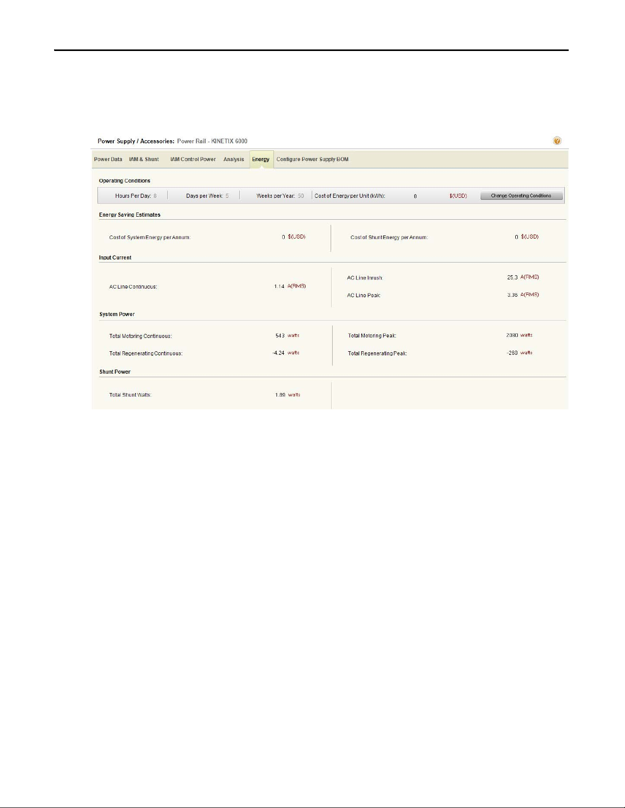
1.2.2.4.1.5. Energy Tab
Click Energy to display the main power supply parameters including Input
Current, System Power, Shunt Power and Energy Savings Estimates.
34 Rockwell Automation Publication MOTION-UM004B-EN-P - October 2012
Page 35

Welcome to Motion Analyzer Software Chapter 1
1.2.2.4.1.6. Configure Power Supply BOM Tab
Click the Configure Power Supply BOM tab to complete the bill of materials
(BOM) for the Power Supply after fully sizing the application. In this tab, you
select options for the power rail, shunt module, filters, circuit breakers, and fuses.
Rockwell Automation Publication MOTION-UM004B-EN-P - October 2012 35
Page 36

Chapter 1 Welcome to Motion Analyzer Software
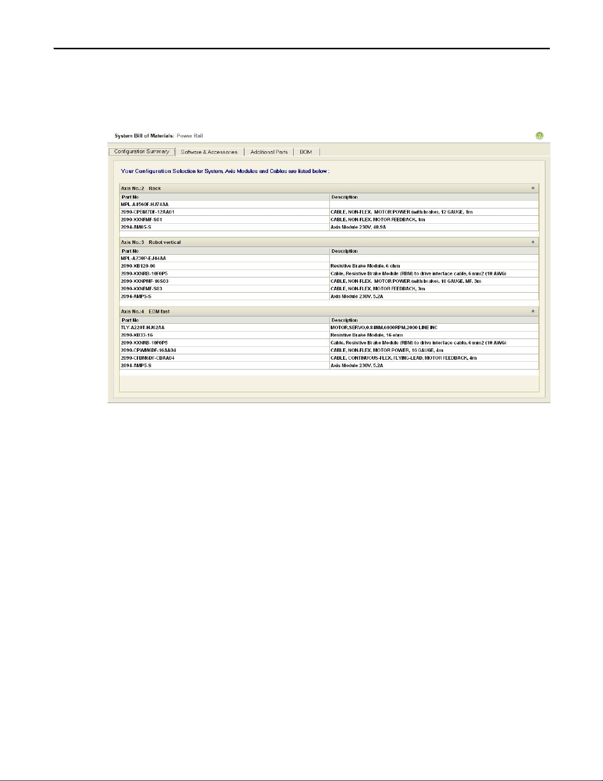
1.2.2.4.1.7. System Bill of Materials (BOM) View
Click BOM view to review the entire BOM (bill of materials) for the system and
add any additional parts that may be needed.
Table 20 - BOM View Tabs
Parameters Description Page
Configuration Summary Tab
Software and Accessories Tab
Additional Parts Tab
BOM Tab
Shows all the axis components in axis order. 37
Contains the Controllers, Software, and other Accessories to complete
your system.
Select any additional components. 39
Displays the full bill of materials (BOM). 40
38
36 Rockwell Automation Publication MOTION-UM004B-EN-P - October 2012
Page 37
Welcome to Motion Analyzer Software Chapter 1
1.2.2.4.1.7.1. Configuration Summary Tab
Click Configuration Summary to display all the axis components and
descriptions in axis order. Scroll down to see all the axes.
Rockwell Automation Publication MOTION-UM004B-EN-P - October 2012 37
Page 38

Chapter 1 Welcome to Motion Analyzer Software
1.2.2.4.1.7.2. Software and Accessories Tab
Click Software and Accessories to complete your system.
To assist in selecting the Sercos cables, click Auto Select to automatically build a
set of these cables with the required lengths to link the axes according to their slot
configuration.
Break-out boards, cables, kits, and various connectors are available to complete
cabling from drive to motor.
Other components such as connectors, safe-off headers, and line filters for
example, are available.
38 Rockwell Automation Publication MOTION-UM004B-EN-P - October 2012
Page 39

Welcome to Motion Analyzer Software Chapter 1
1.2.2.4.1.7.3. Additional Parts Tab
Click Additional Parts to add any additional components you may need.
From the Product Family pull-down menu, choose the Family, Motor Series, and
then by component category to reduce the time required to search for motion
control components. If you know the catalog number, entering that is the
quickest way to find your part.
Rockwell Automation Publication MOTION-UM004B-EN-P - October 2012 39
Page 40

Chapter 1 Welcome to Motion Analyzer Software
1.2.2.4.1.7.4. BOM Tab
Click BOM to display the full bill of materials (BOM) in the same section
headings as the other tabs.
This BOM can be exported to Microsoft Word or Microsoft Excel software by
clicking the appropriate button.
40 Rockwell Automation Publication MOTION-UM004B-EN-P - October 2012
Page 41
Welcome to Motion Analyzer Software Chapter 1
1.2.2.4.2. Power Supply/Accessories - Integrated Drive-Motor (IDM) Systems
The integrated drive-motor (IDM) power interface module (IPIM) is effectively
a power management module for the DC link to a group of individual IDM
units, but to the 2094 power rail it looks like an axis module. Each IPIM module
can handle up to 16 axes, with certain limitations.
Table 21 - IPIM Module Configuration
Options Description Page
Power Data Tab
IPIM Module Selection Tab Lets you select the IPIM module. 42
Cable Length Tab
Control Power Tab
Configure IPIM Module
BOM Tab
View regeneration and motoring data for each IDM unit. 41
Cable selection for connecting IPIM module-to-IDM unit and
IDM unit-to-IDM unit.
• Bar graph for control power
• Summary view
• Details view
Configure the bill of materials (BOM) for the power supply after fully sizing
the application.
43
44
45
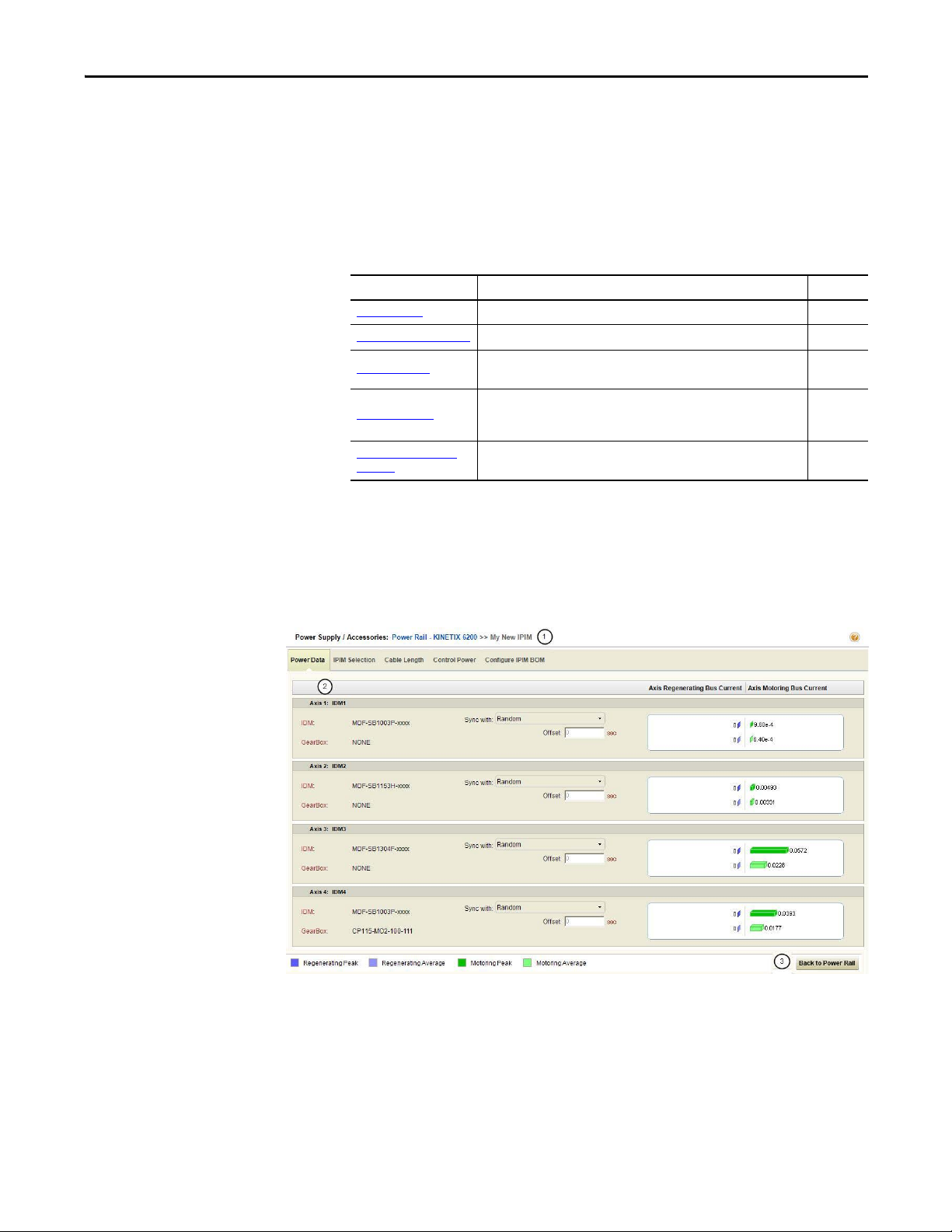
1.2.2.4.2.1. Power Data Tab
Click the Power Data tab to view regeneration and motoring data for each IDM
unit.
Figure 26 - Power Data Tab
Rockwell Automation Publication MOTION-UM004B-EN-P - October 2012 41
Page 42

Chapter 1 Welcome to Motion Analyzer Software
Table 22 - Power Data Tab Descriptions
Options Description
Label 1 in Figure 26
IDM Axis view
(label 2 in Figure 26
Back to Power Rail
(label 3 in Figure 26)
Name of the power rail and selected IPIM module slot is displayed here. Click the power rail
name label switches the view from IPIM view to Power Rail - Power Supply view.
Summary of the all IDM units associated with the selected IPIM module along with the Axis
)
Motoring Bus Current and Axis Regenerating Bus Current values of each IDM unit.
Click to switch the view from IPIM view to Power Rail - Power Supply view.
1.2.2.4.2.2. IPIM Module Selection Tab
Click the IPIM Module Selection tab to select an IPIM module.
Figure 27 - IPIM Selection Tab
Table 23 - IPI M Selection Tab De scri ptio ns
Options Description
Automatic
Selection mode
(label 1 in Figure 27
Utilizations
(label 2 in Figure 27
42 Rockwell Automation Publication MOTION-UM004B-EN-P - October 2012
Manual Select Manual to manually select the IPIM module.
Current
Selection
Search Search button is disabled because only one catalog number is available.
IPIM
DC Bus Current
RMS Limit
)
DC Bus Current
Instantaneous
Limit
Select Automatic for Motion Analyzer software to search for the best IPIM
module solution for the selected slot.
Displays the selected IPIM module catalog number.
Arrows provide the means to scroll forward/backwa rd to smaller/larger
IPIM module catalog numbers.
Graphical representation of DC bus current rms limit for the selected IPIM
module.
Graphical representation of DC bus current instantaneous limit for the
selected IPIM module.
Page 43

Welcome to Motion Analyzer Software Chapter 1
1.2.2.4.2.3. Cable Length Tab
Click the Cable Length tab to select cables for connecting IPIM module-to-IDM
unit and IDM unit-to-IDM unit.
Figure 28 - Cable Length Tab
Table 24 - Cable Length Tab Descriptions
Options Description
From the Cable Length pull-down menus, choose the appropriate cable length for connecting
IPIM module-to-IDM unit and IDM unit-to-unit. The maximum cable lengths in an IDM system
are specified as 25 m (82 ft) IDM unit-to-IDM unit and 100 m (328 ft) total cable length.
IDM Cables
(label 1 in Figure 28
IDM System Graphic
(label 2 in Figure 28
Cable For Specifies the modules the cables will join.
Cable Length Specifies the cable length.
Total Length Specifies the total length of the cables.
Graphical representation of IPIM module, associated IDM units and joining cables. Cable length
)
is displayed over the cables.
Rockwell Automation Publication MOTION-UM004B-EN-P - October 2012 43
Page 44

Chapter 1 Welcome to Motion Analyzer Software
1.2.2.4.2.4. Control Power Tab
Click the Control Power tab for utilization views and to select the number of
sensor inputs and outputs.
Figure 29 - Control Power Tab
Table 25 - Con trol Power Tab Desc riptio ns
Options Description
Utilizations
(label 1 in Figure 29
Selection for Control
Power Usag e
(label 2 in Figure 29
Detailed View
(label 3 in Figure 29
Control
Power
Total Displays the sum of power utilized by all the IDM units.
IPIM Displays the maximum power that can be supplied by the selected IPIM module.
Summary
view
)
Click the Details arrow (refer to Figure 30
)
This table is hidden by default.
This bar graph displays the percentage of power utilized by all IDM units to the
maximum power that can be supplied by IPIM module.
From the pull-down menu, choose the quantity of each of I/O Sensor. Summary
view displays the control power usage and control voltage for each IDM unit.
Figure 30 - Control Power Tab (details arrow)
) to display complete information for each IDM unit.
44 Rockwell Automation Publication MOTION-UM004B-EN-P - October 2012
Page 45

Welcome to Motion Analyzer Software Chapter 1
Figure 31 - Control Power Tab (details revealed)
1.2.2.4.2.5. Configure IPIM Module BOM Tab
Click the Configure IPIM Module BOM tab to select hybrid and network
cables, and other IDM system accessory items.
Figure 32 - Configure IPIM Module BOM Tab
Table 26 - Configure IPIM Module BOM Tab Descriptions
Options Description
Step 1 (Figure 32) IPIM module IPIM module selected on the IPIM Module tab is displayed here.
Step 2 (Figure 32
Step 3 (Figure 32
Step 4 (Figure 32) Hybrid coupler The hybrid coupler connects between two hybrid cables, to bypass an IDM unit.
Step 5 (Figure 33
) Hybrid cables Hybrid cable lengths selected on the Cable Lengths tab are displayed here.
)Network cables
Network
)
bulkhead adapter
Network cables can be routed with the hybrid cables, so network cable lengths
should be the same as the hybrid cable. The IPIM-to-IDM1 cable must have a
straight connector to the IPIM module.
Use the network bulkhead adapter for securing network cables as they pass
through the cabinet.
Figure 33 - Configure IPIM Module BOM Tab
Rockwell Automation Publication MOTION-UM004B-EN-P - October 2012 45
Page 46

Chapter 1 Welcome to Motion Analyzer Software
1.2.2.4.3. Power Supply/Accessories - Single-axis Drive Systems
If your drive family is single axis, for example, Kinetix 300, Kinetix 350,
Kinetix 3, or Ultra™3000, Ultra5000, and Ultra1500, you must configure a shunt
or specify no shunt required.
Figure 34 - Power Supply/Accessories Dialog Box
Table 27 - Power Supply/Accessories Tabs (refer to Figure 34
Parameters Description Page
Power Data Tab View the regeneration and motoring data for each axis. 47
Shunt Tab
Analysis Tab
Energy Tab
Configure Power Supply
BOM Tab
46 Rockwell Automation Publication MOTION-UM004B-EN-P - October 2012
Select the external shunt resistors for single-axis systems. 47
Analyze the drive module activity in terms of bus voltage and system current.
With this tab, you can also simulate changes to the system parameters.
View input current values and energy savings estimates for each axis. 49
Configure the bill of materials (BOM) for the power supply after fully sizing
the application.
)
48
50
Page 47

Welcome to Motion Analyzer Software Chapter 1
1.2.2.4.3.1. Power Data Tab
Use the Power Data tab to view regeneration and motoring data for each axis.
Table 28 - Power Data Tab Properties (refer to Figure 34)
Parameters Description
Axis Histograms
The axis histograms show a multi-axis representation of axis currents including Peak
Motoring, Average Motoring, Peak Regenerating, and Average Regenerating.
1.2.2.4.3.2. Shunt Tab
Click Search to automatically configure the shunt module catalog number for
each axis.
Figure 35 - Shunt Tab
Table 29 - Shunt Tab Properties
Parameters Description
Shunt selection
(refer to Figure 23
Continuous Current
utilization bar
(refer to Figure 23 )
Rockwell Automation Publication MOTION-UM004B-EN-P - October 2012 47
Click Search to configure external shunts if an existing internal shunt for a given drive is
outside its rating. If you need more than one external shunt, click search to select multiple
)
shunt modules. You can also select a compatible shunt manually.
The drive continuous and peak current utilizations and the shunt continuous current
utilization histograms are displayed in percentage form. Click the drive module or shunt
catalog number to view its product specification.
Page 48

Chapter 1 Welcome to Motion Analyzer Software
1.2.2.4.3.3. Analysis Tab
Click Analysis to display plots of drive module activity in terms of the DC bus
voltage and DC bus current:
• The red line is the bus voltage trip point.
• The green line is the DC bus voltage.
• The grey line is the bus current.
Figure 36 - Analysis Tab Dialog Box
Table 30 - Analysis Tab Properties
Parameters Description
Shunt On The voltage level where the shunt enables.
Shunt Off The voltage level where the shunt turns off.
(1)
Simulation Parameters
(refer to Figure 25)
Zoom
(refer to Figure 25
(1) Click Apply to implement these changes.
48 Rockwell Automation Publication MOTION-UM004B-EN-P - October 2012
Trip The voltage level where the drive trips on an overvoltage fault by changing the trip volts.
Resistance The shunt resistance level in ohms.
Power Changing the power value modifies how much energy the shunt resistor can dissipate continuously.
Capacitance Changing the capacitance value changes the DC bus capacitance.
Time From/
Voltage From
)
Time Slice
Check these boxes to adjust the X- and Y-axis values for the plot. Click Plot to implement these changes.
The Time Slice variable sets the time interval for the Analysis tab. Because the shunt switching action is modeled
during selection, this value needs to be very short to obtain an accurate shunt selec tion (0.1 ms, for example).
However, if the total cycle time is more than a few seconds, the calculation time may become excessive. The time is
equal to the longest axis cycle.
Page 49
Welcome to Motion Analyzer Software Chapter 1
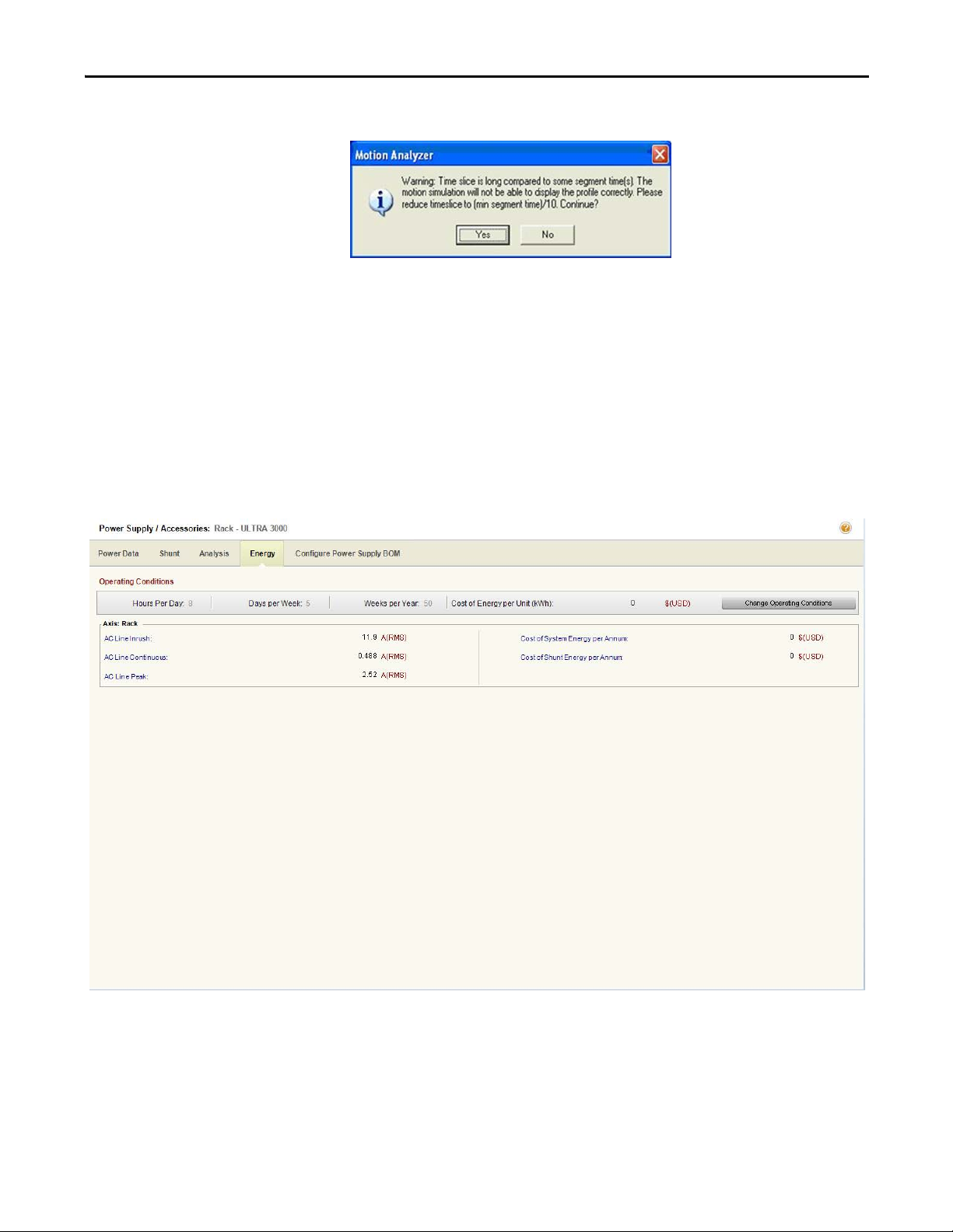
If the time slice variable is increased, this error message often appears.
This time slice message may also appear as soon as you click Solution on the main
taskbar. In this case, clicking Yes or No still takes you to the Solution tab, but if
you click No, some pre-calculations are not performed.
This time slice message often appears if one of the motion cycles is a cam, which
often has very short time segments. In this case, click No to ignore the message.
1.2.2.4.3.4. Energy Tab
Click the Energy tab to display the main power supply parameters including
input current, cost of system energ y, and cost of shunt energy.
Rockwell Automation Publication MOTION-UM004B-EN-P - October 2012 49
Page 50

Chapter 1 Welcome to Motion Analyzer Software
1.2.2.4.3.5. Configure Power Supply BOM Tab
Click the Configure Power Supply BOM tab to complete the bill of materials
(BOM) for the Power Supply after fully sizing the application. In this tab, you
select options for the shunt module, filters, circuit breakers, and fuses.
50 Rockwell Automation Publication MOTION-UM004B-EN-P - October 2012
Page 51

Welcome to Motion Analyzer Software Chapter 1
1.2.2.4.4. Power Supply/Accessories – AC/DC Power Sharing Systems (Kinetix 5500 drives)
If your drive family is Kinetix 5500, you must define a valid power sharing
configuration and then configure a shunt and capacitor, or specify if no shunt or
capacitor are required.
Figure 37 - Power Supply/Accessories
Parameters Description
DC Sharing
Power Configuration options
(label 1 in Figure 37
Axes sharing – AC/DC
(label 2 in Figure 37
)
AC Sharing Only
Select the AC and DC sharing option for each axis individually.
Table 31 - Power Configuration Options (refer to label 1 in Figure 37
Use this option for shared AC/DC or common bus configuration. The following restrictions are imposed on the
number of drives allowed in common bus, or shared AC/DC configuration, based on the converter capacity and/or
connectors:
• Single phase operation is not allowed.
• The bus master drive or drives with an AC connection should have the same power rating (catalog number).
• The bus master drive or drives should always have a rating equal to, or greater than, the followers.
• The number of bus master drives cannot exceed the following rule: Frame 3 = two drives; Frame 2 = four drives;
Frame 1 = eight drives.
• The number of follower drives is driven by the frame of the master drive or drives, and cannot exceed this rule:
Frame 1 drive = only four more bus followers can be added; Frame 2 drive = only six more bus followers can be
added.
• Converter power output should be reduced by 30% of the sum of the individual converter power capacities of
drives configured for shared AC/DC.
• The maximum number of drives in a bus power sharing group is eight drives.
3-phase AC input power can be shared among drives with the same power rating. No DC bus connections are
allowed in this configuration. AC power sharing allows you to minimize the system components, such as circuit
breakers and fuses. The following limitations apply when drives are configured for sharing AC input power:
• Single-phase operation is not allowed.
• All drives must be configured for the same converter voltage rating.
• Drives with the same power rating (catalog number) can be used for this configuration.
• The maximum number of drives that can be configured for shared AC operation is limited by the amp capacity of
the AC input connector. The following rules apply: Frame 1 drives can share AC with up to five drives of the same
rating; Frame 2 drives can share AC with up to three drives of the same rating; Frame 3 drives can share AC with
up to two drives of the same rating.
)
Rockwell Automation Publication MOTION-UM004B-EN-P - October 2012 51
Page 52

Chapter 1 Welcome to Motion Analyzer Software
1.2.2.4.4.1. DC Sharing
Use the DC Sharing configuration to group axes to share a common DC bus and
input AC supply (optional).
Table 32 - Power Supply/Accessories Tabs (refer to Figure 37)
Parameters Description
Power Data Tab View regeneration and motoring data for each axis.
Conver ter and Shunt Tab Select the shunts and capacitor for your system.
Analysis Tab
Energy Tab View input current values and energy savings estimates for each axis.
Configure Power Supply BOM Tab
Analyze the drive module activity in terms of bus voltage and system
current. With this tab, you can also simulate changes to the system
parameters.
Configure the bill of materials (BOM) for the power supply after fully sizing
the application.
1.2.2.4.4.1.1. Power Data Tab
Click the Power Data tab to view regeneration and motoring data for each axis.
Parameters Description
Axis histograms
Random/Sync
relationship
Offset
The axis histograms show a multi-axis representation of axis currents including peak motoring, average motoring, peak regenerating, and average
regenerating.
The phase relationship between the various axis motion profiles in a common DC bus system affects the peak bus-current requirement. For example, if all axes
accelerate simultaneously (for example, synchronous operation), the bus current demand is much greater than if each accelerates in turn. The pull-down menu
lets you choose Random or Synchronized mode for axes operation. At least one axis should be set to random as the reference axis. Other axes may be set to
synchronized or random relative to the reference axis.
The safe setting for system sizing is all Random mode. In this case, the worst case current demand for each axis is automatically lined up by adjusting the phase
relationship of the axis motion profiles. If the phase relationship is known and will not change, the cycle profiles should be set up in the correct relationship and
appropriate synchronized set. This relationship is maintained by the system sizing algorithm and may result in a smaller drive being selected.
If all axis motion profiles are the same length and start at their correct respective positions at the default time, then the offsets will be zero. Otherwise, a
specified time offset may be used to align the motion profiles correctly.
Figure 38 - Power Data Tab
Table 33 - Power Data Tab Properties (refer to Figure 38
)
52 Rockwell Automation Publication MOTION-UM004B-EN-P - October 2012
Page 53

Welcome to Motion Analyzer Software Chapter 1
1.2.2.4.4.1.2. Converter and Shunt Tab
Select shunt and capacitor modules for your system.
Figure 39 - Converter and Shunt Tab
Table 34 - Converter and Shunt Tab Properties (refer to Figure 39
Parameters Description
Shunt Selection and Component
Listing
(label 1 in Figure 39)
Calculation Utilizations
Utilization
(label 2 in Figure 39
)
In this section you select a shunt for each axis, and a capacitor module for the
system.
Click Calculate Utilizations to analyze the behavior of the bus, and to calculate
the drive and shunt utilizations.
The drive continuous and peak current utilizations and the shunt continuous
current utilization histograms are displayed in this area. Click the drive module
catalog number to view the drive specifications.
)
Rockwell Automation Publication MOTION-UM004B-EN-P - October 2012 53
Page 54

Chapter 1 Welcome to Motion Analyzer Software
1.2.2.4.4.1.3. Analysis Tab
Click the Analysis tab to conduct detailed analysis of the drive module activity in
terms of bus volts and system current, along with the capability of simulating
changes to the system parameters. The analysis activities are described as follows:
• The red line is the bus voltage trip point.
• The green line is the DC bus voltage.
• The grey line is the bus current.
Figure 40 - Analysis Tab
Table 35 - Analysis Tab Properties (refer to Figure 40
Parameters Description
Simulation Parameters
(refer to Figure 40)
Zoom window
(refer to Figure 40)
54 Rockwell Automation Publication MOTION-UM004B-EN-P - October 2012
Adjust these parameters to obser ve how changes to the parameters impact the bus voltage and current.
Time From/
Voltage From
Time Slice
Check these boxes to adjust the X- and Y-axis values for the plot.
The Time Slice variable sets the time interval for the analysis display. Because the shunt switching action is modeled during
selection, this value needs to be very short to obtain an accurate shunt selec tion (0.1 ms, for example). However, if the total cycle
time is more than a few seconds, the calculation time may become excessive.
The time is equal to the longest axis cycle. In the case of a very long length of time, we suggest that a longer time slice be used
for early checks, but a time slice of less than 0.1 ms should be used for the final selection.
)
Page 55

Welcome to Motion Analyzer Software Chapter 1
If the time is increased, the time slice error message often appears.
This time slice message may also appear as soon as you click Solution on the main
taskbar. In this case, clicking Yes or No still takes you to the Solution tab, but if
you click No, some pre-calculations are not performed.
This time slice message often appears if one of the motion cycles is a cam, which
often has very short time segments. In this case, click No to ignore the message.
1.2.2.4.4.1.4. Energy Tab
Click the Energy tab to display the main power supply parameters including
Input Current, System Power, Shunt Power, and Energy Savings Estimates.
Figure 41 - Energy Tab
Rockwell Automation Publication MOTION-UM004B-EN-P - October 2012 55
Page 56

Chapter 1 Welcome to Motion Analyzer Software
1.2.2.4.4.1.5. Configure Power Supply BOM Tab
Click the Configure Power Supply BOM tab to complete the bill of materials
(BOM) for the power supply after fully sizing the application. In this tab, you
select options for the power rail, shunt module, filters, circuit breakers, and fuses.
Figure 42 - Configure Power Supply BOM Tab
1.2.2.4.4.2. AC Sharing Only
Use the AC Sharing Only configuration to group axes to share input AC supply
only, with no DC bus sharing.
Figure 43 - Power Configuration Tab for AC Sharing Only Mode
56 Rockwell Automation Publication MOTION-UM004B-EN-P - October 2012
Page 57

Welcome to Motion Analyzer Software Chapter 1
Table 36 - Power Supply/Accessories (refer to Figure 43)
Parameters Description
Power Data Tab View regeneration and motoring data for each axis.
Conver ter and Shunt Tab
Analysis Tab
Energy Tab View input current values and energy savings estimates for each axis.
Config ure Power Sup ply BOM
Tab
Select the shunt and capacitor for your system.
Analyze the drive module activity in terms of bus voltage and system current. With this
tab, you can also simulate changes to the system parameters.
Configure the bill of materials (BOM) for the power supply after fully sizing the
application.
1.2.2.4.4.2.1. Power Data Tab
Use the Power Data tab to view regeneration and motoring data for each axis.
Figure 44 - Power Data Tab
Table 37 - Power Data Tab Properties (refer to Figure 44
Parameters Description
Axis histograms
The axis histograms show a multi-axis representation of axis currents including peak motoring,
average motoring, peak regenerating, and average regenerating.
)
Rockwell Automation Publication MOTION-UM004B-EN-P - October 2012 57
Page 58

Chapter 1 Welcome to Motion Analyzer Software
1.2.2.4.4.2.2. Shunt Tab
Select the shunt and capacitor module for your system.
Figure 45 - Shunt Tab
Table 38 - Shunt Tab Properties (refer to Figure 45
Parameters Description
Shunt selection
(refer to Figure 45
Continuous Current utilization bar
(refer to Figure 45
)
)
Click Search to configure external shunts if an existing internal shunt for a given
drive is outside its rating. If you need more than one external shunt, click search
to select multiple shunt modules. You can also select a compatible shunt
manually.
The drive continuous and peak current utilizations and the shunt continuous
current utilization histograms are displayed in percentage form. Click the drive
module or shunt catalog number to view its product specification.
)
58 Rockwell Automation Publication MOTION-UM004B-EN-P - October 2012
Page 59

Welcome to Motion Analyzer Software Chapter 1
1.2.2.4.4.2.3. Analysis Tab
Click the Analysis tab to display plots of drive module activity in terms of the DC
bus voltage and DC bus current. The analysis activities are described as follows:
• The red line is the bus voltage trip point.
• The green line is the DC bus voltage.
• The grey line is the bus current.
Figure 46 - Analysis Tab
Table 39 - Analysis Tab Properties (refer to Figure 46
Parameters Description
Shunt On The voltage level where the shunt enables.
Shunt Off The voltage level where the shunt turns off.
Simulation
Parameters
(refer to Figure 46)
Zoom window
(refer to Figure 46
(1) Click Apply to implement these changes.
(1)
Tri p
Resistance The shunt resistance level in ohms.
Power
Capacitance Changing the capacitance value changes the DC bus capacitance.
Time From/
Voltage From
)
Time Sli ce
The voltage level where the drive trips on an overvoltage fault by
changing the trip volts.
Changing the power value modifies how much energy the shunt
resistor can dissipate continuously.
Check these boxes to adjust the X- and Y-axis values for the plot.
Click Plot to implement these changes.
The Time Slice variable sets the time interval for the Analysis tab.
Because the shunt switching action is modeled during selection,
this value needs to be very short to obtain an accurate shunt
selection (0.1 ms, for example).
However, if the total cycle time is more than a few seconds, the
calculation time may become excessive. The time is equal to the
longest axis cycle.
)
Rockwell Automation Publication MOTION-UM004B-EN-P - October 2012 59
Page 60

Chapter 1 Welcome to Motion Analyzer Software
If the time is increased, the time slice error message often appears.
This time slice message may also appear as soon as you click Solution on the main
taskbar. In this case, clicking Yes or No still takes you to the Solution tab, but if
you click No, some pre-calculations are not performed.
This time slice message often appears if one of the motion cycles is a cam, which
often has very short time segments. In this case, click No to ignore the message.
1.2.2.4.4.2.4. Energy Tab
Click the Energy tab to display the main power supply parameters including
input current, cost of system energ y, and cost of shunt energy.
Figure 47 - Energy Tab
60 Rockwell Automation Publication MOTION-UM004B-EN-P - October 2012
Page 61

Welcome to Motion Analyzer Software Chapter 1
1.2.2.4.4.2.5. Configure Power Supply BOM Tab
Click the Configure Power Supply BOM tab to complete the bill of materials
(BOM) for the power supply after fully sizing the application. In this tab, you
select options for the power rail, shunt module, filters, circuit breakers, and fuses.
Figure 48 - Configure Power Supply BOM Tab
Rockwell Automation Publication MOTION-UM004B-EN-P - October 2012 61
Page 62

Chapter 1 Welcome to Motion Analyzer Software
1.2.3. Preferences Tab
The Preferences tab contains three sections.
Figure 49 - Preferences Tab Options
Table 40 - Preferences Tab Descriptions
Options Description
The product databases may be modified to restrict selections to those
items marked by you. This may be used, for example, by a distributor
to select from a range of popular stock items. Drives, Motors, and
Gearboxes may all be marked.
Creates a database of custom motors with your own specifications that
can be sized and analyzed.
Updates the Motion Analyzer database on your personal computer to
the latest database available from the Motion Analyzer server.
Enter details about the end-user. Entries appear on printouts.
)
Lets privileged users select the electronic keys to provide additional
features and functions.
Lets you set default units for all data entry. Choice includes a user
Custom set.
Lets you set the operating conditions used to calculate Life
calculations of Bearing Life, Bal l Screw Life, Roller Screw Life, and Strip
Seal Life in Motion Analyzer software.
Database
(label 1 in
Figure 49 )
Settings
(label 2 in
Figure 49 )
Options
(label 3 in
Figure 49
My Preferred Database
(refer to Figure 50)
User Defined Database
(refer to Figure 51)
Check for Updates
User Inform ation
(refer to Figure 52
Key Status
Units of Measure
(refer to Figure 53)
)
Operating Conditions
(refer to Figure 54)
Notes Launches system notes for the application.
Figure 50 - Preferred Data Dialog Box
62 Rockwell Automation Publication MOTION-UM004B-EN-P - October 2012
Page 63

Figure 51 - User Defined Motors Dialog Box
Figure 52 - Options - User Information Dialog Box
Welcome to Motion Analyzer Software Chapter 1
Rockwell Automation Publication MOTION-UM004B-EN-P - October 2012 63
Page 64

Chapter 1 Welcome to Motion Analyzer Software
Figure 53 - Options - Units of Measure Dialog Box
Figure 54 - Options - Operating Conditions Dialog Box
64 Rockwell Automation Publication MOTION-UM004B-EN-P - October 2012
Page 65

Welcome to Motion Analyzer Software Chapter 1
1.2.4. Export – Import Tab
The Export - Import tab contains two sections.
Figure 55 - Export - Import Tab Options
Table 41 - Export - Import Tab Descriptions
Options Description
Project Data to Word Exports the application data to a Microsoft Word document.
Launches the export wizard to let you export the profile data of the
selected axis. Refer to More Options Profile Editor Mode on page 142.
Exports motion system information to RSLogix™ 5000 software to
use it in the next step of your design process.
Imports the axis data from another axis either of current application
or from any other Motion Analyzer application.
Imports the Profile data for selected axis. Impor ted Profile Data must
have been previously exported by Motion Analyzer software.
Export
(label 1 in Figure 55
Import
(label 2 in Figure 55)
Profile Data
BOM to Word Exports Bill of Material to Microsoft Word document.
)
BOM to Excel Exports Bill of Material to Microsoft Excel file.
Export To RSLogix 5000
Axis Data
Profile Data
1.2.4.1. Export to RSLogix 5000 Wizard
Once you have selected a motor and drive in Motion Analyzer software, you can
export motion system information to RSLogix 5000 software and use it in the
next step of your design process. You can generate an RSLogix 5000 file (.L5X),
version 18.00, 19.00, 20.00, or 21.00. Applications can be exported to
RSLogix 5000 software as new .L5X files or as updates to existing .L5X files.
Rockwell Automation Publication MOTION-UM004B-EN-P - October 2012 65
Page 66

Chapter 1 Welcome to Motion Analyzer Software
1.2.4.1.1. Export Options - Create a New .L5X File
1. From the Export-Import menu, click Export To RSLogix 5000.
The Output Format Selection dialog box opens.
2. Select Create a New L5X and from the pull-down menu and choose the
RSLogix 5000 software version you intend to use.
3. Click Next.
The Axis Mapping dialog box opens.
66 Rockwell Automation Publication MOTION-UM004B-EN-P - October 2012
Page 67

Welcome to Motion Analyzer Software Chapter 1
1.2.4.1.1.1. Axis Mapping
Information about .L5X file that Motion Analyzer generates is displayed at the
top of the screen as read only information.
Table 42 - Axis Mapping Properties
Attribute Description
Controller Name
Controller Type
Chassis Type
Motion Analyzer software assigns a default name for the controller. You can edit this once
the file has been loaded.
Motion Analyzer software creates a file with a default controller type. You can edit this
once the file has been loaded.
Motion Analyzer software creates a file with a default Logix chassis. You may change your
chassis type once the file has been loaded.
The name you define for each axis in Motion Analyzer software is used to create a
RSLogix 5000 axis tag. Underscore characters replace spaces in the name defined
in Motion Analyzer software. To change these names you must exit the Export to
RSLogix 5000 wizard and change the names by right-clicking each axis in the
Motion Analyzer explorer tree.
All axes in your Motion Analyzer (.mba) file appear in the table. If they will
export without trouble, a green status check is displayed.
Rockwell Automation Publication MOTION-UM004B-EN-P - October 2012 67
Page 68

Chapter 1 Welcome to Motion Analyzer Software
Table 43 - Axis Mapping Symbols
Attribute Description
Axes will export without errors.
Axes with warning icon only partially export to RSLogix 5000 software. A note at the
bottom of the screen indicates what is wrong.
Not recommended icon. A note at the bottom of the screen indicates what is wrong.
If problems occur with selected catalog numbers, a warning icon and a note at the
bottom of the dialog box appears.
Figure 56 - Axis with Warning Icon
If export isn’t possible, a note at the bottom of the dialog box indicates what the
problem is. This axis is not exported to RSLogix 5000 software.
Figure 57 - Axis with Not Recommended Icon
If the number of axes a sercos module can support is exceeded, a new sercos
module is added into the pull-down menu in the third column. This is selectable
for the rest of the axes. This new module is also exported to the .L5X file.
4. Click Next.
68 Rockwell Automation Publication MOTION-UM004B-EN-P - October 2012
Page 69

Welcome to Motion Analyzer Software Chapter 1
IMPORTANT
The Target Location dialog box opens.
1.2.4.1.1.2. Save and Import the L5X File
1. Click Browse to select a target location and save the .L5X file.
2. Click Finish.
Do not use spaces or special characters in the name, or RSLogix 5000
software will not open the file.
Rockwell Automation Publication MOTION-UM004B-EN-P - October 2012 69
Page 70

Chapter 1 Welcome to Motion Analyzer Software
3. Open RSLogix 5000 software.
4. Browse to your .L5X file and open it.
70 Rockwell Automation Publication MOTION-UM004B-EN-P - October 2012
Page 71

Welcome to Motion Analyzer Software Chapter 1
5. Browse to the location where you would like to store your .acd file.
6. Click Import.
Rockwell Automation Publication MOTION-UM004B-EN-P - October 2012 71
Page 72

Chapter 1 Welcome to Motion Analyzer Software
Your motion system information imports from Motion Analyzer software.
Exceptions include warnings noted on the Axis Mapping dialog box.
72 Rockwell Automation Publication MOTION-UM004B-EN-P - October 2012
Page 73

Welcome to Motion Analyzer Software Chapter 1
1.2.4.1.2. Export Options - Update an Existing L5X File
1. From the Export-Import menu, click Export To RSLogix 5000.
The Output Format Selection dialog box opens.
2. Select Update an Existing L5X and click browse to find the file you wish to
update.
3. Click Next.
Rockwell Automation Publication MOTION-UM004B-EN-P - October 2012 73
Page 74

Chapter 1 Welcome to Motion Analyzer Software
The Axis Mapping dialog box opens.
4. Make changes as needed to the existing file.
5. Click Next.
74 Rockwell Automation Publication MOTION-UM004B-EN-P - October 2012
Page 75

The Target Location dialog box opens.
Welcome to Motion Analyzer Software Chapter 1
Table 44 - Export Output Target Properties
Attribute Description
Save Select Save to replace the old L5X file with the updated file.
Save As Select Save As to create an updated L5X file in a new location and/or with a new name.
6. Open the file in RSLogix 5000 software as described earlier and notice
that the motion system information from your Motion Analyzer software
file has been included.
7. Click Finish.
Rockwell Automation Publication MOTION-UM004B-EN-P - October 2012 75
Page 76

Chapter 1 Welcome to Motion Analyzer Software
1.2.5. Bill of Materials (BOM) Tab
The Bill of Materials (BOM) tab contains two sections.
Figure 58 - Bill of Materials (BOM) Tab Options
Table 45 - Bill of Materials (BOM) Tab Descriptions
Options Description
This is a combo item and contains the axis names of all the axes in the
Drives Group that have a solution. It lets you navigate to the
Configure Axis BOM tab of Axis view where you can configure the
BOM for the axis chosen.
This is a combo item for single-axis drive family and a button item for
multi-axis drive family. For single-axis drive family, it contains the
axis names of all the axes in Drives Group that have a solution. It lets
you navigate to Configu re Power Supply B OM tab of the Power Supply
& Accessories view where you can configure the Power Supply BOM
for the system.
Navigate to the Software & Accessories tab of System BOM view on
page 38.
Navigate to the Additional Parts tab of System BOM view on page 39.
Navigate to the BOM tab of System BOM view on page 37.
Confi gure
(label 1 in Figure 58)
Export
(label 2 in Figure 58
Axis
System Module
Software and
Accessories Tab
Additional Parts Tab
Configuration
Summary Tab
BOM to Word Exports Bill of Material to Microsoft Word document.
)
BOM to Excel Exports Bill of Material to Microsoft Excel file.
1.2.6. Help Tab
The Help tab contains one section.
Figure 59 - Help Tab Options
Table 46 - Help Tab Descriptions (refer to Figure 59
Options Description
Motion Analyzer Help Launches Motion Analyzer help.
Activate Motion
Analyzer
Send Feedback Provides contact information for Motion Analyzer software support.
Release Notes Launches the Release Notes for the installed Motion Analyzer software revision.
About Motion Analyzer
76 Rockwell Automation Publication MOTION-UM004B-EN-P - October 2012
Launches the Motion Analyzer Activation wizard. You can Purchase License or Activate their
Motion Analyzer installation (refer to Figure 60
Launches the About Motion Analyzer dialog box that displays details of the installed copy of
Motion Analyzer software (refer to Figure 61
)
).
).
Page 77

Figure 60 - Motion Analyzer Activation Wizard
Welcome to Motion Analyzer Software Chapter 1
Figure 61 - About Motion Analyzer
Rockwell Automation Publication MOTION-UM004B-EN-P - October 2012 77
Page 78

Chapter 1 Welcome to Motion Analyzer Software
1.3. Explorer View
The Explorer view provides a Windows Explorer style graphical user interface for
accessing components in your Motion Analyzer software application.
For multi-axis drive systems, the axes are added under the Power Rail node in the
Explorer hierarchy view.
Figure 62 - Typical Multi-axis Drive Explorer View
For single-axis drive systems, the axes are added under the Project node in the
Explorer hierarchy view.
Figure 63 - Typical Single-axis Drive Explorer View
For drive families that allow stand alone as well as power sharing group (Kinetix
5500 drives), a mix of drive group and stand alone axes can be added under the
Project Node.
78 Rockwell Automation Publication MOTION-UM004B-EN-P - October 2012
Page 79

Welcome to Motion Analyzer Software Chapter 1
Figure 64 - Typical AC/DC Power Sharing System (Kinetix 5500) Explorer View
Options Description
The project node contains two types of groups. The Power Rail/Drive Group (of the selected product family) and an unallocated group.
Power Rail No de
Drives Group Node
Axis Module Node
Project Node
Axis Module Node
IPIM Module Node
IDM Unit Node
Empty Slot Node
Table 47 - Explorer View Structure (refer to Figure 62
Applies to multi-axis drive families. Shown is the power rail icon, drive family na me, and power rail catalog
number. The default name for this node is Drives Group 1, however, it is renamed when a solution for any
axis under this group is defined.
For single-axis family, the default name is Drives Group 1. For multi-axes family, the default name is Power
Rail 1. Also, for multi-axis family, after the drive family is defined, the power rail displays many empty slots
until each slot is allocated a module.
Applies to drive families that allow AC and DC power sharing (Kinetix 5500). Shown is the drive group icon
and drive name.
Axis node consists of two levels. First level displays the slot number of the power rail (available only for
multi-axis families), axis name, drive catalog number, and the solution status of the axis. Second level
displays the motor catalog number for the selected solution. Additionally, if there is a warning in the axis,
then a warning triangle is also displayed beside the solution status.
When the solution is not yet selected, then only the axis node is displayed and instead of drive catalog
number, Incomplete is displayed.
This node displays the slot number that the IPIM module is assigned to on the power rail along with the
name of the IPIM module, catalog number of the selected IPIM module, and the IPIM module status.
IDM unit node is similar to axis module node except that the IDM unit node consists of only a single node
representing the axis solution.
Applies to multi-axis drive families. It is visible after a multi-axis drive family is selected.
)
Unallocated Axis Node
Status Symbols
The Unallocated Axes Node is where axes independent of other axes can be created. An unallocated axis can be allocated to a Drive Group using the allocate
button located in the Home Tab
Additionally, if the power supply solution is present, then the status of the selected power supply solution is also displayed, as described below.
Indicates that the selected power supply solution and all children support the application requirement.
Indicates that the selected power supply solution or any one of the children marginally support the application requirement.
Indicates that the selected power supply solution or any one of the children is not recommended for the application. Additionally, this icon is
also displayed when the IAM module for the power rail has not been sized.
on the menu bar or by dragging and dropping the axis.
Rockwell Automation Publication MOTION-UM004B-EN-P - October 2012 79
Page 80

Chapter 1 Welcome to Motion Analyzer Software
Notes:
80 Rockwell Automation Publication MOTION-UM004B-EN-P - October 2012
Page 81

Sizing Your System
Top ic Pa ge
Identify Your Load 82
Linear Loads 83
Rotary Loads 86
Rotary Complex Loads 87
Application Template Loads 96
From SolidWorks 120
Define Your Profile 139
Less Options Profile Editor Mode 140
More Options Profile Editor Mode 142
Specify Your Linear Load Mechanism 178
Belt Drive 180
Lead Screw 181
Chain and Sprocket 182
Rack and Pinion 183
Linear Motor 184
Electric Cylinders 186
Linear Stages 187
Linear Thrusters 189
Specify Your Transmission 191
Compute Using Inertia and Ratio 193
Compute Using Pitch Circle Diameter 194
Compute Using Number of Teeth 195
Choose Your Motor Series 196
Choose Your Electric Cylinder Series 199
Choose Your Drive Family 201
Chapter 2
Rockwell Automation Publication MOTION-UM004B-EN-P - October 2012 81
Page 82

Chapter 2 Sizing Your System
2.1. Identify Your Load
A load is a device that transfers the actuator output to the desired end effectors.
Loads do not affect the motion type.
Figure 65 - Load Type Tab
Table 48 - Load Type Options
Load Type Description Page
Linear Loads Load moves in a straight line. 83
Rotary Loads Load rotates and the system has no translation to linear motion. 86
Rotary Complex Loads
Application Template
Loads
From Soli dWorks
Rotary motion can be translated to linear motion, and vise versa. Iner tia,
friction, and/or torque values for the system change with time.
Simplify data entry dramatically where the application is appropriate. The
Application Templates include Press Roll Feed (Constant Time or Angle),
Carriage Cut Off, Cutter Knife Drive, Advanced Templates, and Power Speed.
Used to obtain load data to aid in sizing your application for the appropriate
motors, drives, and accessories.
87
96
120
82 Rockwell Automation Publication MOTION-UM004B-EN-P - October 2012
Page 83

2.1.1. Linear Loads
For a Linear application, the load moves in a straight line.
Figure 66 - Linear Load Type
Sizing Your System Chapter 2
Table 49 - Linear Load Parameters
Parameter Description
Load Mass Mass of the linear load.
Applied Force
Coeff of Friction
Inclination
Any external force (+/-) acting on the load. Positive force acts to oppose positive
movement; down the inclination surface if inclination is non-zero. The arrow on the
graphic indicates the force direction.
Coefficient of friction (μ). It is a unitless value, which is used to calculate the force of
friction. It is largely dependent on the nature of the surfaces in contact with each other.
Typical values for the coefficient of friction can be found in engineering tables. This value,
along with the load mass (for example, Load weight + Table/Slide/Carriage weight),
determines the amount of motor force or torque necessary to move a slide or table, for
example.
Angle of inclination from the horizontal. The limits for this value are 0 and 90°. In the
horizontal case (0° inclination), the Table Mass, Belt/Chain Mass, and/or Slide Mass are
not affected by gravity, whereas in the vertical case (90° inclination), only the table mass
is affected by gravity. Values for Table Mass, Belt/Chain Mass, and/or Slide Mass may be
entered on the Mechanism tab (a future step in the workflow) if a Belt Drive, Lead Screw,
Chain and Sprocket, or Rack and Pinion are selected.
If the Inclination angle is between 0 and -90°, you must enter the angle as a positive
number and invert the motion profile. For example, enter a 45° angle value on the Load
tab and a negative velocity in More Options Profile Editor Mode
this will result in an under- calculation of the regenerative energy.
on page 142. Failure to do
Rockwell Automation Publication MOTION-UM004B-EN-P - October 2012 83
Page 84
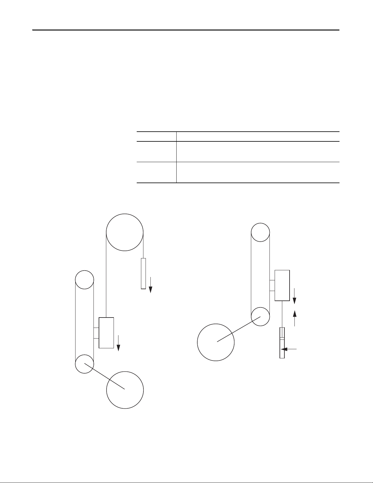
Chapter 2 Sizing Your System
Counterbalance Mass
Mass Counterbalance
Force Counterbalance
Counte rbalance
Cyli nder
Air Pressure
Force
Weig ht
Weig ht
Weig ht
Drive Belt
Drive Belt
Load Ma ss
Load Mass
Motor
Motor
2.1.1.1. Advanced Considerations - Counterbalances
In a counterbalanced system, unbalanced mass should be entered as Table Mass
and balanced mass as Belt/Chain Mass. Values for Table Mass, Belt/Chain Mass,
and/or Slide Mass may be entered on the Mechanism tab (a future step in the
workflow) if a Belt Drive, Lead Screw, Chain and Sprocket, or Rack and Pinion
are selected.
There are two main types of counterbalance.
Table 50 - Counterbalance Types
Type Description
Mass
Counterbalance
Force
Counterbalance
Figure 67 - Counterbalance Types
A 100% counterbalance doubles the load mass entered on the Load tab. Friction is usually
negligible and the net force is zero. Accelerations are normally limited to less than gravity
2
(9.81 m/s
) to maintain the suspension tension.
A 100% counterbalance means there is zero net force, but usually adds significant friction,
especially hydraulic types. For example, pneumatic, hydraulic, or spring. The increase in load
mass is usually negligible.
84 Rockwell Automation Publication MOTION-UM004B-EN-P - October 2012
Page 85

Sizing Your System Chapter 2
2.1.1.1.1. Mass Counterbalance
• Vertical load with a 100% mass counterbalance
Set the Inclination field to zero and enter a load mass two times greater
than the load into the Load Mass field.
• Vertical load with less than 100% mass counterbalance.
Set the Inclination field to zero and enter the load mass plus the
counterbalance mass into the Load Mass field. Add an external positive
force equal to the following into the Applied Force field:
F = (M
load
- M
counterbalance
where a = acceleration due to gravity = 9.81 m/s
) a
2
2.1.1.1.2. Force Counterbalance
For a vertical load with a 100% force counterbalance, you have two choices:
• Set the Inclination field to zero and enter the load mass into the Load Mass
field.
• Set the Inclination field to 90°, and enter the load mass into the Load Mass
field. Add an external negative force equal to the load weight into the
Applied Force field.
For a vertical load with less than 100% force counterbalance, set the Inclination
field to 90° and put the load mass into the Load Mass field. Add an external
negative force equal to the counterbalance force into the Applied Force field.
Be sure to add some allowance for friction. Hydraulic type counterbalances are
notorious for high friction, which is usually speed-dependent. Because a mass
counterbalance cannot easily handle this directly, take the friction force at the
maximum speed, convert the friction force to torque at the drive shaft and add
this torque to the Losses field in the Actuator tab.
Rockwell Automation Publication MOTION-UM004B-EN-P - October 2012 85
Page 86

Chapter 2 Sizing Your System
2.1.2. Rotary Loads
For a rotary application, the load rotates and the system has no translation to
linear motion.
Figure 68 - Rotary Load Type
Table 51 - Rotary Load Parameters
Parameter Description
Primary Inertia
Friction This is the force resisting the relative motion of two surfaces against each other.
(1) Use the Inertia Calculator Template on page 105 to calculate the inertia value for your application, if the value is not readily
available.
(1)
This is the inertia of any balanced load about the axis of rotation. For example, if the main
mass is a circular table which is driven about its own axis of symmetry, then primary
inertia is equal to the table inertia.
86 Rockwell Automation Publication MOTION-UM004B-EN-P - October 2012
Page 87

Sizing Your System Chapter 2
2.1.3. Rotary Complex Loads
A complex rotary load is non-linear, which means that the load position is not
directly proportional to the input shaft position as it is with standard actuator
types. A simple example is a crank, where the load velocity is sinusoidal with a
constant shaft speed. The Crank and Four Bar Linkage templates are available for
these applications.
The main challenge with non-linear mechanisms is that the inertia value varies
with shaft angle. This means that even at constant shaft speed, a torque that varies
with the rate of change of inertia is required to maintain that speed. The same is
true of an unbalanced load in which external forces, such as gravity, induce torque
values that depend only on shaft angle, not velocity or acceleration.
The Rotary Complex load separates the dynamic inertia values from the motion
profile so that, having calculated inertia for a range of shaft positions, the motion
profile can be varied without having to re-calculate inertia at each shaft position.
Figure 69 - Rotary Complex Load Type
Rockwell Automation Publication MOTION-UM004B-EN-P - October 2012 87
Page 88

Chapter 2 Sizing Your System
Table 52 - Complex Load Data Options
Option Description
Complex Load Data
(label 1 in Figure 69
(1)
Motion
(label 2 in Figure 69)
Graph tab
(label 3 in Figure 69
User Defined
)
Templates
Repeating
Limited Range
# Data point number; this number is arbitrary.
Position Driving shaft angle with refe rence to the sta rting angle.
Inertia Load inertia for the given shaft angle.
Applied Torque Torque applied at the given position.
Friction Torque Torque loss due to friction.
Description Available for you to enter optional notes.
The Graph tab of the display window shows the inertia, applied torque, and friction torque
values as a function of shaft position based on the data entered in the table on the left (label 2
)
in Figure 69 ).
Impo rt loa d data f rom an ex terna l file i nto the Complex L oad Data table o n
page 90.
Use the Unbalanced Load and Crank temp lates to calculate load data and
enter it in the Complex Load Data table on page 90.
With this option, the first and last points should be identical so that the
motion profile can be repeated (for example, zero and 360 °). Motion
Analyzer software assumes that rotation may continue indefinitely in
either direction.
With this option, the first and last points indicate the maximum and
minimum positions permitted.
(1) The complex load data (position, inertia, and torque, for example) is entered manually, imported, or calculated in the available
Rotary Complex Templates.
It is important to start with the mechanism in the appropriate position. Click
Start Condition
on the toolbar at the top of the More Options Profile Editor
Mode dialog box to input the motion profile start condition.
Figure 70 - Graph Tab
88 Rockwell Automation Publication MOTION-UM004B-EN-P - October 2012
Page 89
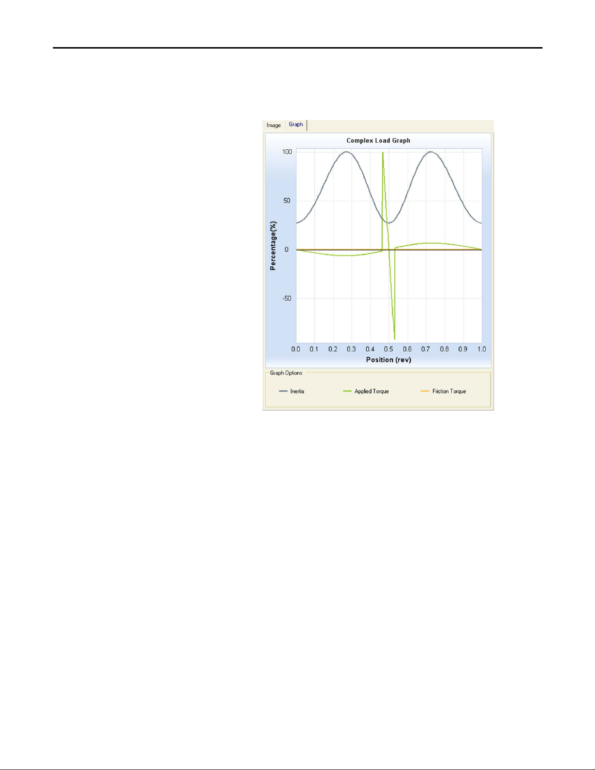
Sizing Your System Chapter 2
In this Crank application, the green applied torque curve shows a sharp peak
around 180° when a high force is encountered near the end of the linear stroke.
Figure 71 - Crank Application Example
Rockwell Automation Publication MOTION-UM004B-EN-P - October 2012 89
Page 90

Chapter 2 Sizing Your System
IMPORTANT
2.1.3.1. User Defined
For the User Defined data entry option, calculations are typically made with a
spreadsheet. Once the data is arranged in columns to match the Complex Load
Data table, you can copy the data to the clipboard and paste it into the table. The
columns are tab delimited, which is the default format for Microsoft Excel
software. Alternatively, you can create and import a text file.
Before pasting data make sure that the column units match those of the data.
2.1.3.2. Templates
The Rotary Complex templates can be used to calculate Complex Load Data for
Unbalanced Load and Crank application types.
Figure 72 - Rotary Complex Loads
There are two Rotary Complex templates available to assist in calculating data for
the Complex Load Data table (label 2 in Figure 72
Table 53 - Template Options (label 1 in Figure 72)
Template Description Page
Unbalanced Load
Tem p l at e
Crank Template
90 Rockwell Automation Publication MOTION-UM004B-EN-P - October 2012
Lets you enter parameters for an Unbalanced Load application. 91
Lets you enter parameters for Crank applications. 93
).
Page 91

Sizing Your System Chapter 2
2.1.3.2.1. Unbalanced Load Template
This template lets you enter parameters for an unbalanced load application.
Figure 73 - Unbalanced Load Template
Motion Analyzer software assumes that the axis of rotation is parallel to the
ground if no axis angle is entered and that unbalanced masses create a gravity
related torque. Secondary Inertia, Secondary Mass and Axis Separation
parameters are required to take into account gravity induced torque values.
Figure 74 - Axis of Rotation Parallel to Ground with No Axis Angle Defined
Rockwell Automation Publication MOTION-UM004B-EN-P - October 2012 91
Page 92

Chapter 2 Sizing Your System
If the gravity torque (Secondary Mass * 9.81 m/s2 * Axis separation2) is known to
be small as compared to the acceleration torque or motor nominal torque, then it
may not be necessary to include the unbalanced mass effects.
ATT EN TI ON : If the angle of movement in any profile segment is such that the
gravity torque changes significantly during that segment (a common
occurrence) then break the segment into smaller portions.
Table 54 - Unbalanced Load Parameters (refer to Figure 73)
Parameter Description
Primary Inertia
Losses The losses consist of the torque lost in the system due to friction.
Secondary Inertia
Secondary Mass The unbalanced mass.
Axis Separation The distance between the secondary mass’ center of gravity and the axis of rotation.
Axis Angle
(1)
(1)
The inertia of any balanced load about its own axis of rotation. For example, if the main
mass is a circular table which is driven about its own axis of symmetr y, then Primary
Inertia is equal to the table inertia.
The moment of inertia of the unbalanced mass about its own center of gravity.
The starting angle of rotation. Zero indicates that at the start of the motion profile, the
center of gravity lies vertically below the center of rotation. This is the position of the load
if it is allowed to swing freely. Positive rotation is clockwise.
(1) Use the Inertia Calculator Template on page 105 to calculate the inertia value for your application, if the value is not readily
available.
92 Rockwell Automation Publication MOTION-UM004B-EN-P - October 2012
Page 93

Sizing Your System Chapter 2
IMPORTANT
TIP
2.1.3.2.2. Crank Template
The Crank template is used to calculate the load profile for a given application,
based on either input shaft velocity or linear load velocity.
This template should only be used for constant inertia. Do not set secondary
mass or secondary inertia when using this template.
Figure 75 - Crank Template
Figure 76 - Animated Display (for reference)
Parameter entry descriptions are displayed when the cursor is held over an
entry field for several seconds.
Rockwell Automation Publication MOTION-UM004B-EN-P - October 2012 93
Page 94

Chapter 2 Sizing Your System
Table 55 - Crank Template Parameters
Parameter Description
For reference to make sure that entered data is accurate and particularly that the ori entation of the crank is correct. The animation rotates the crank so that
the system can be better visualized. The X/Y plane is horizontal.
Vertical Slider (Left)
Horizontal Slider (Top)
Animated Display
(label 1 in Figure 75)
Template Options
(inside red box
in Figure 75
)
Mechanical Data
(label 2 in Figure 75
Export to Complex Load
(label 3 in Figure 75
Horizontal Slider (Scale) Sets the display scale.
Horizontal Slider (Speed) Sets the animation speed.
Black Arrow Represents the ex ternal force and th e arrow length is proportional to the applied force.
2D/3D Toggles between two and three-dimensional representations of the crank.
Thick Lines Check this box if you would like the graphical displays to be shown with a thicker line.
Animate Click to run the simulated crank image through the specified motion profile.
Stop Click to stop the animation.
Calculate Click to calculate the external torque and reflected inertia values.
Crank Radius The distance between crank shaft and crank pin.
Crank Inertia
(1)
Connecting Rod Length
Connecting Rod Mass The total mass of the connecting rod.
Conrod C of G from Crankpin The distance between the crank pin and the connecting rod center of gravity.
Conrod Inertia about C of G
Linear (Load) Mass The mass of the load attached to the connecting rod at the gudgeon pin.
Linear (Load) Offset The distance from the linear motion center line to the crankshaft axis.
Force Start Position The distance between gudgeon (wrist) pin and crank shaft center when force is applied.
Force End Position The distance between the gudgeon (wrist) pin and crank shaft center when force stops.
)
Force at En d
(3)
Force v Angle Box When this box is checked, the force varies according to shaft angle rather than linear position.
Draw Click this button to show the geometry at the start angle/position.
Logix Cam
Crankshaft Inclination
Crank Plane Inclination
Start Angle The starting angle for the Crank load profile.
End Angle The ending angle for the Crank load profile.
)
Points The number of points you would like to divide the load profile into.
Sets the crankshaft inclination. Set this parameter before starting the animation. The 0y button sets the angle to 90°. The
current angle is displayed in the Mechanical Data window.
Sets the linear slide inclination. The 0z button sets the angle to 0°. The current angle is displayed in the Mechanical Data
window. The true angle to the horizontal is dependent on both slider positions since it is a compound angle.
The inertia of the crank alone, when the connecting rod is disconnected.
(2)
The distance from the crank pin center to the gudgeon (wrist) pin center.
(1)
The inertia of the connecting rod about its own center of gravity.
The magnitude of the force at the ending point.
Click this button to transfer the geometrical data to the clipboard for pasting into the RSLogix 5000 Cam Editor. The
master axis is a virtual axis and the slave axis is the crank axis. A trapezoidal move of the virtual axis produces a
trapezoidal load profile at the gudgeon pin. The master data must increase positively so only that part of the cam that
satisfies this requirement is exported.
This displayed value is the angle of the crank shaft with respect to the XY (horizontal) plane. 90° indicates vertical and
gravity has no effect.
This displayed value is the angle with respect to the horizontal plane along which the linear mass moves. Zero degrees
indicates horizontal and gravity has no effect.
94 Rockwell Automation Publication MOTION-UM004B-EN-P - October 2012
Page 95

Sizing Your System Chapter 2
Table 55 - Crank Template Parameters (continued)
Parameter Description
Peak Inertia The calculated maximum reflected inertia at the crankshaft.
Results
(label 4 in Figure 75
Peak Ext. + Grav. Torque
)
Apply Click to apply the load profile data and close the window.
Cancel Click to close the window without applying any data.
Chart Display
(label 5 in Figure 75
(1) Use the Inertia Calculator Template on page 105 to calculate the inertia value for your application, if the value is not readily available.
(2) Setting this length to zero configures the mechanism as a Scotch Yoke, where the linear load follows a simple harmonic motion.
(3) If the Force at Start is different from the Force at End, the force varies between these two limits according to gudgeon pin position or crank angle. If the values are equal, a constant force is applied.
The Chart Display displays the crank velocity, the inertia that is reflected to the crankshaft, and the crank torque due to external influences such as gravity
)
and applied force. These are the parameters which will be applied.
The Peak External Force + Gravity Torque is the calculated peak torque, generated from the external linear force and
gravity.
Rockwell Automation Publication MOTION-UM004B-EN-P - October 2012 95
Page 96

Chapter 2 Sizing Your System
2.1.4. Application Template Loads
The application templates let you enter pre-configured mechanism application
data.
Figure 77 - Application Template Load Type
Table 56 - Application Template Options
Template Type Description Page
Press Roll Feed (constant
time/constant angle)
Carriage Cut Off
Cutter Knife Drive
Advanced Templates
Power/Speed Templates
This application is typically cutting strip material into pre-set lengths with a
‘Press Shear’ (heavy-duty knife). The material must be stationary when the
cut is made and the cut takes place over a fixed amount of time or a fixed
angle of the driving crank whose speed is varied to match the cut rate.
This application is typically cutting strip material into pre-set lengths with a
‘Flying Shear’ (heavy-duty knife on a moving carriage). The shear must be
stationary relative to the material (for example, moving at li ne speed) when
the cut is made and the cut takes a fixed time.
This application is typically cutting strip material into pre-set lengths with a
‘Rotary Knife’ (heavy-duty knife blades mounted on a pair of rotating
drums). The blades must be stationary relative to the material (for example,
moving at line speed) when the cut is made and the cut takes place over a
fixed drum angle.
These templates let you enter data for complex mechanisms. Advanced
Templates include the Inertia Calculator, Crank, Winder/Unwinder, and Four
Bar Linkage.
These templates let you enter torque and speed values that are used to
calculate the power requirement for the application.
97
100
102
104
118
96 Rockwell Automation Publication MOTION-UM004B-EN-P - October 2012
Page 97

Sizing Your System Chapter 2
2.1.4.1. Press Roll Feed (constant time/constant angle)
This application is typically cutting strip material such as steel into pre-set lengths
by means of a press shear (heavy-duty knife). The material must be stationary
when the cut is made and the cut takes place over a fixed amount of time or a
fixed angle of the driving crank whose speed is varied to match the cut rate.
Strip material is unwound from a reel at constant surface speed and fed via
separately driven leveler rolls into one end of a looping pit (a free-hanging loop of
material providing storage). On the other side of the loop, a pair of feeder rolls
grips the material and moves it forward the required cut length and then stops.
After the cut is complete, the material is moved again. The average velocity of the
nip/feeder rolls must be equal to the constant velocity of the unwinder and
leveler rolls.
Figure 78 - Press Roll Feed - Constant Time
Figure 79 - Press Roll Feed - Constant Angle
Rockwell Automation Publication MOTION-UM004B-EN-P - October 2012 97
Page 98

Chapter 2 Sizing Your System
Parameter Description
Moving Material Mass The mass of the material in the loop and on the flat before the Nip/Feed rolls.
Bias Force The force required to overcome the force of gravity on the loop.
Drive Roll Diameter The diameter of the roll in direct contact with the strip, driven from the motor.
Load
(label 1 in Figure 78
or
Total Roll Inertia
Figure 7 9)
Cut (Waiting) Time
Cut (Waiting) Angle
Max Average Line Speed
Critical Preferences
(1)
(label 2 in Figure 78 or
Figure 7 9)
Cuts/ min
System Properties
(label 3 in Figure 78
Figure 7 9)
Settling Time
or
Cosine Compensat ion
Linear Select this option for standard linear acceleration and deceleration ramps.
Motion Type Properties
(label 4 in Figure 78
or
S-Curve
Figure 7 9)
Triangular Move
Table 57 - Press Roll Feed Parameters
(3)
(3)
(2)
The total inertia of the strip material at the drive shaft.
The time during which the material must be stationar y in an accurate position. This value is only required for Press Roll Feed Constant Time applications (refer to the red boxes in images above).
The crank angle during which the material must be stationary in an accurate position. This value is only required for Press Roll
Feed - Constant Angle applications (refer to the red boxes in images above).
Select this option for data entry when the maximum design speed of the constant-speed sections of the line is known. This
speed does not refer to the peak velocity of the feeder section, which is determined by Motion Analyzer software.
Min. Cut length at
Max line speed
When you select the option to enter data based on Max Average Line Speed, this data is required. This is
the critical condition on which the sizing process is performed. To cut shorter lengths than this critical
length, the line speed must be reduced.
Select this option for data entry when the number of cuts made by the system per minute is known.
Max. Cut length at
Cuts/ min
When you select the option to enter data based on Cuts/min, this data is required. This is the critical
condition on which the sizing process is performed. To cut longer lengths than this critical length, the
line speed must be reduced.
This is the time required for the system to achieve the required position accuracy before the cut commences. The finer the
required accuracy, the longer the settling time value. This time is typically 20 to 75 ms for an A servo system.
This option is only required for Press Cutter Knife Drive applications. The Cosine Compensation is used to make sure that while
the press cutter knife is in contact with the material being cut, the horizontal component of the knife’s velocity matches the
material speed.
Select this option for ‘S’ shaped acceleration and deceleration ramps that are used to produce smoother motion. You need to
enter the percent jerk value for this option.
Select this option for a triangular load profile. This option is only required for Press Roll Feed - Constant Angle applications (see
red box in Figure 79
).
(1) At very long cut lengths, the limiting factor, determined by the design speed of the leveler rolls and unwinder, is the maximum line speed. As cut length is reduced, the servo has to index more and more
rapidly until the peak or RMS (root mean squared) torqu e limit is rea ched. To cut shorter lengths than this critical length, the line speed must be reduced. Sizing is based on this critical length, maximum
line speed and cut time, which are typically specified.
(2) Use the Inertia Calculator Template
(3) You can enter this data manually or use the Loop Calculator
on page 105 to calculate the inertia value for your application, if the value is not readily available.
on page 99, to determine the value.
98 Rockwell Automation Publication MOTION-UM004B-EN-P - October 2012
Page 99

Sizing Your System Chapter 2
Click in Figure 78 or Figure 79 to determine the Moving Mass and Bias
Force parameters by using the Loop Calculator.
Figure 80 - Loop Calculator
Table 58 - Loop Calculator Parameters
Parameter Description
Density
Material
(label 1 in Figure 80)
Loop
(label 2 in Figure 80
Computed Parameters
(label 3 in Figure 80
Thickness Strip material thickness.
Width Strip material width.
Flat Length Strip material flat length as defined in the Press Roll Feed Diagram.
Loop Length Strip material loop length as defined in the Press Roll Feed Diagram.
)
Loop Depth Strip material max loop depth as defined in the Press Roll Feed Diagram.
Moving Mass When you click Compute, the Loop Calculator displays the Moving Mass
)
Bias Force
Choose strip material from the pull-down menu or enter the density value
manually.
and Bias Force values based on the values you entered for the parameters
above. These values are entered in the Application Template when you click
OK.
Rockwell Automation Publication MOTION-UM004B-EN-P - October 2012 99
Page 100

Chapter 2 Sizing Your System
2.1.4.2. Carriage Cut Off
This application is typically cutting strip material such as steel into pre-set lengths
by means of a Flying Shear (heavy-duty knife mounted on a moving carriage).
The shear must be stationary relative to the material (for example, moving at line
speed) when the cut is made and the cut takes a fixed time.
Strip material is unwound from a reel at constant surface speed and fed via
separately driven leveler rolls. After the cut is complete, the shear is stopped then
moved back to its start position. It must accelerate to match the line speed at the
correct position to cut the required length of material.
Figure 81 - Carriage Cut Off Template
100 Rockwell Automation Publication MOTION-UM004B-EN-P - October 2012
 Loading...