

Page 1

Quick Start
Original Instructions
Second Generation MobileView Tethered
Operator Terminal
Catalog Numbers 2711T-B10I1N1, 2711T-T10I1N1-TC
Page 2

Second Generation MobileView Tethered Operator Terminal
Topi c Pag e
MobileView 2711T Terminal Dimensions and Weight 3
MobileView 2711T Terminal Component Description 3
Safety Precautions and Elements 4
The Second Generation MobileView 2711T Te rminal 7
The MobileView IP65 Junction Box 12
Initial Power Up of the Second Generation MobileView 2711T Terminal 29
Shut Down the Second Generation MobileView 2711T Term inal 42
MobileView Mounting Brackets 43
Europea n Communitie s (EC) Direc tive Complia nce 44
Second Generation MobileView Terminal Specifications 45
IP65 Junction Box Specifications 46
MobileView Accessories 48
Additional Resources 49
The following publication provides a brief overview of how to install and operate the second
generation MobileView™ 2711T terminal. For more detailed information on this terminal, refer
to MobileView 2711T Tethered Operator Terminal User Manual, publication 2711T-UM001
which is available online at https://www.rockwellautomation.com/global/literature-library/
overview.page.
,
IMPORTANT This quick start publication must be kept throughout the entire service life of the second
generation MobileView 2711T terminal.
Summary of Changes
This quick start publication contains new and updated information as indicated in the following
table.
Topi c Page
Revised Operating Te mperature in Environmental table. 46
2 Rockwell Automation Publication 2711T-QS002D-EN-P - March 2021
Page 3
Second Generation MobileView Tethered Operator Terminal
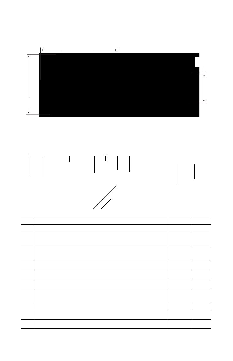
352 mm (13.86 in.)
274 mm
(10.79 in.)
108.5 mm
(4.27 in.)
All MobileView 2711T terminals weigh 1550 g (3.42 lb) without options.
8 9
1
23467
5
10 9
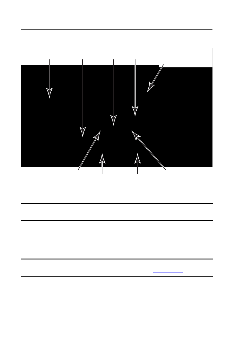
MobileView 2711T Terminal Dimensions and Weight
MobileView 2711T Terminal Component Description
Item
Description
1
Membrane keypad with tactile feedback
2
10 inch WXGA (1280 x 800 pixels) TFT color LCD display with analog-resistive
touch screen
3
Illuminated emergency stop (E-stop) push button, twin-circuit, N.C. contacts,
24V DC, 500 mA max
4
Backside membrane keypad with tactile feedback
5
USB port
6
Product nameplate
7
Handle to hold the terminal, to store the connection cable, and to attach to the
mounting bracket
8
3-position, twin circuit, enabling switch for safety system interface
9
Plug for alternate cable outlet not used (meets degree protection IP65)
10
Back cover to access connection compartment
(1) The 2711T-T10I1N1-TC MobileView terminal does not have this feature.
Rockwell Automation Publication 2711T-QS002D-EN-P - March 2021 3
(1)
Standard Option
–•
•–
•–
–•
•–
•–
•–
•–
•–
•–
Page 4
Second Generation MobileView Tethered Operator Terminal
Safety Precautions and Elements
This section covers general safety precautions and important information on the power supply,
illuminated emergency stop (E-stop) switch, and enable switches that are used with the second
generation MobileView 2711T terminal.
General Safety
It is important to follow the instructions in this document in all circumstances. Failure to do so
can result in potential sources of danger or the possible override of safety features that are
integrated in the terminal.
Besides the safety instructions in this document, you must also use safety precautions and
accident prevention measures that are appropriate to the situation.
ATTENTION: Consider or perform the following as part of general safety.
• Verify that interrupted processes can be properly restarted after power failures or power dips.
Do not allow any dangerous operating conditions to occur, even temporarily.
• In situations where faults that occur within the automation system could cause personal injury
or significant damage to machinery and equipment, take extra safety measures to confirm that
the system remains in an acceptable o perating condition.
• When applying functional safety, restrict access to qualified, authorized personnel who are
trained and experienced.
• Verify that unauthorized persons are not allowed to adjust settings or make memory
modifications that can lead to dangerous situations.
• Test the functionality of the illuminated E-stop button and enabling switch at least once every
six months. Verify that the machine or plant operation stops when the button is pushed.
• If the second generation MobileView 2711T terminal and controller do not communicate with a
point-to-point connection, then keypad data could transmit with a delay. An Ethernet switch
that is used between the second generation MobileView 2711T terminal and controller is
recommended for a higher speed connection.
• When a second generation MobileView 2711T terminal has been exposed to shock (for
example, it is dropped on the ground), test to verify that the E-stop button and enabling switch
still function properly.
• The USB port on the backside of the second generation MobileView 2711T terminal is only for
maintenance. Do not operate the terminal while a USB drive is connected to it.
• Risk assessment and risk reduction are important precautionary measures for machine safety.
For more information, see ISO 12100.
Programmable Electronic Systems
ATTENTION: Personnel responsible for the application of safety-related Programmable Electronic
Systems (PES) shall be aware of the safety requirements in the application of the system and shall
be trained in using the system.
4 Rockwell Automation Publication 2711T-QS002D-EN-P - March 2021
Page 5
Second Generation MobileView Tethered Operator Terminal
MobileView 2711T Terminal Operation
See the MobileView 2711T Tethered Operator Terminal User Manual, publication
2711T-UM001, for more handling instructions to avoid terminal malfunctions or damage.
Power Supply
The second generation MobileView 2711T terminal meets the Safety Class III requirements for
electrical shock in accordance with EN 61131-2. See Electrical on page 45 for the DC power
supply requirements for the second generation MobileView 2711T terminal, IP65 junction box,
and 22-pin connection cable.
Supply the junction box and terminal exclusively from power sources with safety extra-low
voltage (SELV) or protected extra-low voltage (PELV) circuit protection according to
EN61131-2.
Specifications of power supply lines in the connection cable are:
2
• Cross section: 26 AWG (0.126 mm
• Material: zinc-coated copper strand
• Line resistance: <136 Ω/km (<219 Ω/mi)
ATTENTION: The 24V DC power supply to the control cabinet or operator panel must have a fuse
that is rated 3.15 A (maximum) and complies with UL 248.
Failure to install a fuse can result in fire from component failure.
)
Enabling Switch
On the second generation MobileView 2711T terminal, the enabling switch consists of a 3position operating element with two independent circuits.
ATTENTION: Only the operator of the enabling device on the second generation MobileView
2711T terminal is allowed in the dangerous area or zone.
The enabling switch is only suitable a s a safety device if the operator of the enabling switch on the
second generation MobileView 2711T terminal recognizes the dangerous situation and reacts in
time to avoid the danger.
Consider reduced speed of movements as a precautionary measure, which can be done through
the risk assessment of machinery.
Rockwell Automation Publication 2711T-QS002D-EN-P - March 2021 5
Page 6
Second Generation MobileView Tethered Operator Terminal
Foreseeable Misuse of Enabling Switch
Foreseeable misuse is when the enabling switch is modified so it stays in the enabling position.
The foreseeable misuse of the enabling switch must be restricted. The following measures are
recommended, which cause the machine to stop in manual mode.
• Inquiry of the enabling switch when you turn on the machine/plant, and inquiry of the
enabling switch when you change the operating mode from automatic to manual (the
enabling switch must not be in the enabling position).
• The enabling switch must be released within a defined time period and pushed into the
enabling position again, with the time length defined by the activity.
Illuminated Emergency Stop (E-stop) Push Button
The illuminated E-stop push button of the second generation MobileView 2711T terminal meets
the requirements of ISO 13850. The push button must be designed as a Category 0 or Category 1
emergency stop
contacts to an appropriate monitoring system must meet the safety level that results from the risk
assessment of the machine. See Risk Assessment of Machinery
The E-stop has two potential-free, normally closed contacts to connect external peripherals, a
nominal operating voltage of 24V (safety low voltage in accordance with EN61131-2), and a
maximum operating current of 500 mA at 24V DC.
by the risk assessment for the machine. The connection of the force-guided
on page 7.
ATTENTION: Illuminated E-stop push buttons that are not fully functional can have fatal
consequences.
Illuminated E-stop push buttons must be effective under all circumstances in all operating modes
of a machine or plant.
• When the illuminated E-stop push button is not wired into an emergency stop circuit, the
second generation MobileView 2711T terminal must be stored where it is not visible to
operators.
• The reset of an activated E-stop push button must not result in the uncontrolled startup of
machines or installations.
• The illuminated E-stop push button does not replace other safety devices or E-stop buttons
mounted directly on machines.
• Test the functionality of the illuminated E-stop push button at least once every six months.
Verify that machine or plant operation stops when the button is pushed.
• When a second generation MobileView 2711T terminal has been exposed to shock (for
example, it is dropped on the ground), test to verify that the E-stop push button still functions
properly.
6 Rockwell Automation Publication 2711T-QS002D-EN-P - March 2021
Page 7

Second Generation MobileView Tethered Operator Terminal
Back Cover
Risk Assessment of Machinery
For the risk assessment for the machinery, use the standards in ISO 12100, ‘Safety of machinery General principles for design - Risk assessment and risk reduction.’
The control system must be designed for the safety level that results from the risk assessment of
ISO 12100.
The Second Generation MobileView 2711T Terminal
This section provides details on the following topics:
• Remove the Back Cover
• Install the Connection Cable to the Second Generation MobileView 2711T terminal
Remove the Back Cover
This section shows how to remove the back cover of the second generation MobileView 2711T
terminal. When the back cover is removed, you have access to the area that contains all
connectors except the USB port.
SHOCK HAZARD: Disconnect all power to the second generation MobileView 2711T terminal
before you remove i ts back cover.
When the back cover is removed, the
electrostatic discharge (ESD).
second generation
MobileView 2711T terminal is sensitive to
1. Place the second generation MobileView 2711T terminal with the display side down on
a stable, flat surface free of debris.
2. Use a Torx T10 screwdriver to remove
the three screws that secure the back
cover.
TIP The ‘Image Applied’ label on
the back cover was part of the
manufacturing process. You can
remove and discard this label.
3. Carefully lift off the back cover and
set it aside.
Figure 1 on page 8
board of the second generation MobileView
2711T terminal with the back cover removed.
shows the main circuit
Rockwell Automation Publication 2711T-QS002D-EN-P - March 2021 7
Page 8
Second Generation MobileView Tethered Operator Terminal
Connection
Cable
SD
™ Card
(1)
Circuit Board
Serial No. Label
Cable Channel
(1 of 2)
Reset
Button
Cable channel that is used is
only for example. Use channel
that is best suited for your
application.
Cable Channel
(2 of 2)
Cable Connector S3 Connects
to PCB Connector ETH
(Communication Interface)
Cable Connector S2 Connects
to PCB Connector S1
(Power and Safety Connection)
The 2711T-T10I1N1-TC MobileView terminal does not have this feature.
Cable Connector S4 Connects
to PCB Connector S2
(Illuminated Push Button Connection)
Figure 1 - Printed Circuit Board (PCB) with Back Cover Removed
IMPORTANT Use the reset button when MobileView 2711T terminal functionality ‘locks up’ and you cannot
restart from the terminal desktop screen.
Install the Connection Cable to the Second Generation MobileView 2711T terminal
A 22-pin connection cable can be attached on the right or left side of the second generation
MobileView 2711T terminal for right- or left-hand operation.
IMPORTANT The second generation MobileView 2711T terminal is shipped with the cable connection port
open for right-hand operation. For more information, see Figure 2 on page 9
Use the following tools to install the 22-pin connection cable:
• 19 mm open-end wrench or spanner
• Torx T10 screwdriver
•8 mm hex key
8 Rockwell Automation Publication 2711T-QS002D-EN-P - March 2021
.
Page 9

To install the cable, perform the following steps.
Back Cover
Cable connection
with open port
(as factory shipped).
Cable connection
with hex plug
installed.
IMPORTANT The second generation MobileView 2711T terminal is shipped with the above cable-connection
port open for right-hand operation.
When the 22-pin cable is connected to this port, you can hold the terminal with your left arm,
operate the enabling switch with your left hand, and operate the terminal touch screen with your
right hand.
Strain Relief
Connector-cable
Mounting Assembly
Gray Fitting
Second Generation MobileView Tethered Operator Terminal
1. Decide on which cable-connection port of the terminal to install the cable; see Fig ure 2
Figure 2 - Cable Connections on MobileView 2711T Terminal
2. If you want left-hand operation, remove the plug with an 8 mm hex key.
Set the plug aside.
3. Remove the back cover as detailed on page
4. If present, unscrew and remove the gray fitting from
assembly.
5. Unscrew the strain relief from the connector-cable mounting assembly to allow the red
cable to slide freely.
7.
the connector-cable mounting
.
Rockwell Automation Publication 2711T-QS002D-EN-P - March 2021 9
Page 10

Second Generation MobileView Tethered Operator Terminal
6. Gently feed the three terminals at the end of the red cable into the chosen cable
connection and up through the cable channel.
IMPORTANT Do not force the cable terminals through the channel. If you encounter resistance,
slowly pull the cable towards you until it moves freely again.
If necessary, slide the connector-cable assembly far ther down the cable to assist
cable feed through the channel.
7. When the three terminals reach the main circuit board, carefully plug each terminal into its
connection. See
Each terminal is keyed and can fit only one way on its corresponding connection.
IMPORTANT Verify that there is a snap sound when you plug each terminal into its corresponding
8. After each terminal is securely connected, reinstall the back cover.
Use a Torx T 10 scre wdriver to reinstall the three cover screws.
9. Install the connector-cable mounting assembly into the cable connection of the second
generation MobileView 2711T terminal.
10. Reinstall the strain relief to the
11. Tighten the strain relief and the
open-end wrench or spanner.
Torque the connector-cable mounting assembly to 1.2 N•m (10.6 lb•in).
12. If you chose left-hand operation, reinstall the plug in the open cable-connection port
with an
8 mm hex key.
Torque the plug to 1.2 N•m (10.6 lb•in).
Figure 1 on page 8
connection, which confirms that the terminal is properly connected.
for where each terminal is connected.
connector-cable mounting assembly.
connector-cable mounting assembly
with the 19 mm
10 Rockwell Automation Publication 2711T-QS002D-EN-P - March 2021
Page 11
Second Generation MobileView Tethered Operator Terminal
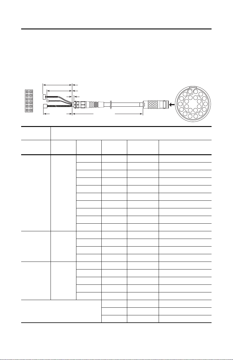
50 mm ±2 (2 in. ±0.08)
10 mm ±2 (0.4 in. ±0.08)
60 mm ±3 (2.4 in. ±0.12)
5, 10, or 15 m
(16.4, 32.8, or 49.2 ft)
Connection Cable
S1 (cable connector)
S1 Pins Detail
S2
S2 Detail
S4
S3
40 mm ±3
(1.6 in. ±0.12)
1
11
9
7
5
3
1
12
10
8
6
4
2
3
4
6
7
9
10
12
13
15
16
17
18
19
20
21
22
11
8
5
14
2
The 22-pin MobileView Connection Cable
The 22-pin connection cable connects the second generation MobileView 2711T terminal to an
IP65 junction box. The connection cable is 5, 10, or 15 m (16.4, 32.8, or 49.2 ft.) long. This
cable withstands water, cleaning agents, motor oil, drilling oils, grease, lubricants, and
condensates that contain hydrochloric acid.
MobileView
Term ina l
PCB Connector
S1,
Power a nd S afet y
Connections
ETH,
Communication
Interface
S2,
Illuminated
Push Button
(1) Shielded.
Connection Cable
Connector
No.
S2
S3
S4
—
Rockwell Automation Publication 2711T-QS002D-EN-P - March 2021 11
Connector
Pin No.
1 10 pink 24V DC
29black GND_IN
37brownE-stop, circuit 2 (+)
4 22 white-green E-stop, circuit 2 (-)
5 6 gray E-stop, circuit 1 (+)
6 19 red-blue E-stop, circuit 1 (-)
7 18 green-brown Enabl ing switch, c ircuit 1 (+)
8 20 yellow Enabling switch, circuit 1 (–)
9 8 green Enabling switch, circuit 2 (+)
10 21 gray-pink Enabling switch, circuit 2 (–)
(1)
1
(1)
2
(1)
3
(1)
6
2 11 violet E-stop, illuminated (+)
4 12 white -pink E-stop, illuminated (–)
1 5 white Semi-wireless jumper
3 14 blue Semi-wireless jump er
513white-blueBox ID
S1 Cable
Pin No.
Cable
Wire Color Signal Description
1blue TD+ (transmit)
2 oran ge TD- (transmit)
3white RD+ (receive)
4 red RD- (receive)
15 Li1 Bridge
16 Li1 Bridge
17 — Not used
Page 12

Second Generation MobileView Tethered Operator Terminal
The MobileView IP65 Junction Box
There are two IP65 junction boxes that work with second generation MobileView terminals and
22-pin connection cables. 2711T-JBIP65DC1 is the IP65 junction box with cord grips that
must be wired by the customer. 2711T-JBIP65DM1 is the IP65 junction box with M12 OnMachine™ connections that is factory wired.
This section provides information on the following topics.
Description Page
Mount the IP65 Junction Box Back Plate 12
Temporarily Mount the IP65 Junction Box 15
Wire the 2711T-JBIP65DC1 Junction Box 15
Configure the 2711T-JBIP65DC1 Junction Box 19
Configure the 2711T-JBIP65DM1 Junction Box 21
Mount the IP65 Junction Box to Its Back Plate 22
Connect M12 On-Machine Connectors to the 2711T-JBIP65DM1 Junction Box 22
Connect Power to IP65 Junction Boxes 24
IP65 Junction Box Status Indicator Lights 25
Connect a Second Generation MobileView Terminal to an IP65 Junction Box 28
Connect a Black Bridge Connector to an IP65 Junction Box 28
Connect to an Ethernet Network 28
Mount the IP65 Junction Box Back Plate
IP65 junction boxes are shipped with their back plate removed so you perform certain functions
for each junction box as needed. This section provides information on how to mount the back
plate of either IP65 junction box.
IP65 junction boxes are shipped with Second Generation MobileView Tethered Operator
Terminal IP65 Junction Box Mounting Template, publication 2711T-DS004
template or the back plate of the IP65 junction box to drill the mounting holes.
IMPORTANT Consider the following before you mount an IP65 junction box:
• Do not mount near a heat source or where direct sunlight is likely.
• Do not mount where excessive mechanical vibrations, excessive dust, humidity, or strong
magnetic fields are likely.
12 Rockwell Automation Publication 2711T-QS002D-EN-P - March 2021
. Use this mounting
Page 13
Second Generation MobileView Tethered Operator Terminal
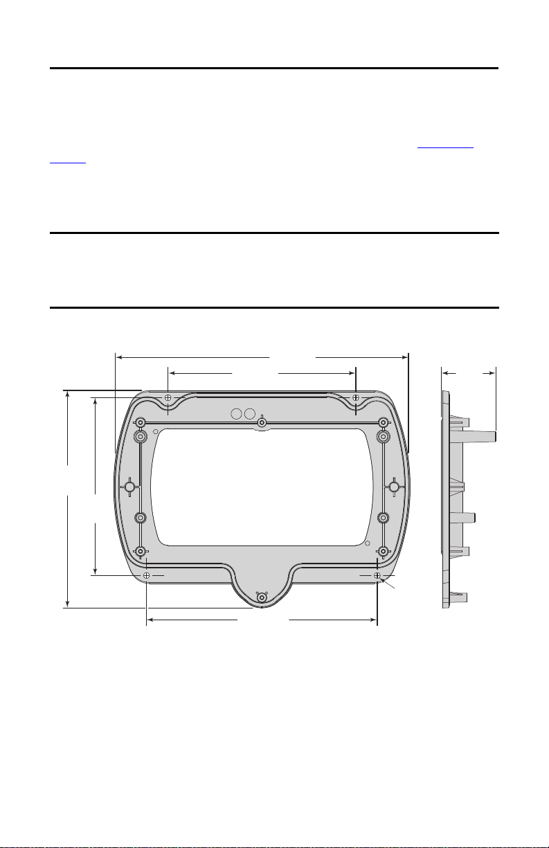
221.1 (8.7)
140 (5.51)
132.5
(5.22)
172 (6.77)
40
(1.57)
162.1
(6.38)
Mounting
Holes,
4 x 4.5 (0.18)
All dimensions are in mm (in.)
2711T-JBBKCOVER Back Cover Plate Accessory
This accessory is for rear access to the junction box from inside a control cabinet. This cover plate
provides quick access to configurable components for both junction boxes (see Figure 6 on
page 19), and to reduce cables that might otherwise be directed through cord grips on the
2711T-JBIP65DC1 junction box.
The cover plate is fitted with a seal. To maintain a tight seal and the IP65 rating (when installed
on an IP65-rated control cabinet), install the cover plate on an even surface.
IMPORTANT Any cable fed through the control cabinet wall must be smaller than the hole in the cabinet
wall.
Provide stress relief for the cables on the control cabinet side when you wire an IP65 junction
box with this back cover plate.
Figure 3 - 2711T-JBBKCOVER Back Cover Plate Dimensions
Rockwell Automation Publication 2711T-QS002D-EN-P - March 2021 13
Page 14
Second Generation MobileView Tethered Operator Terminal
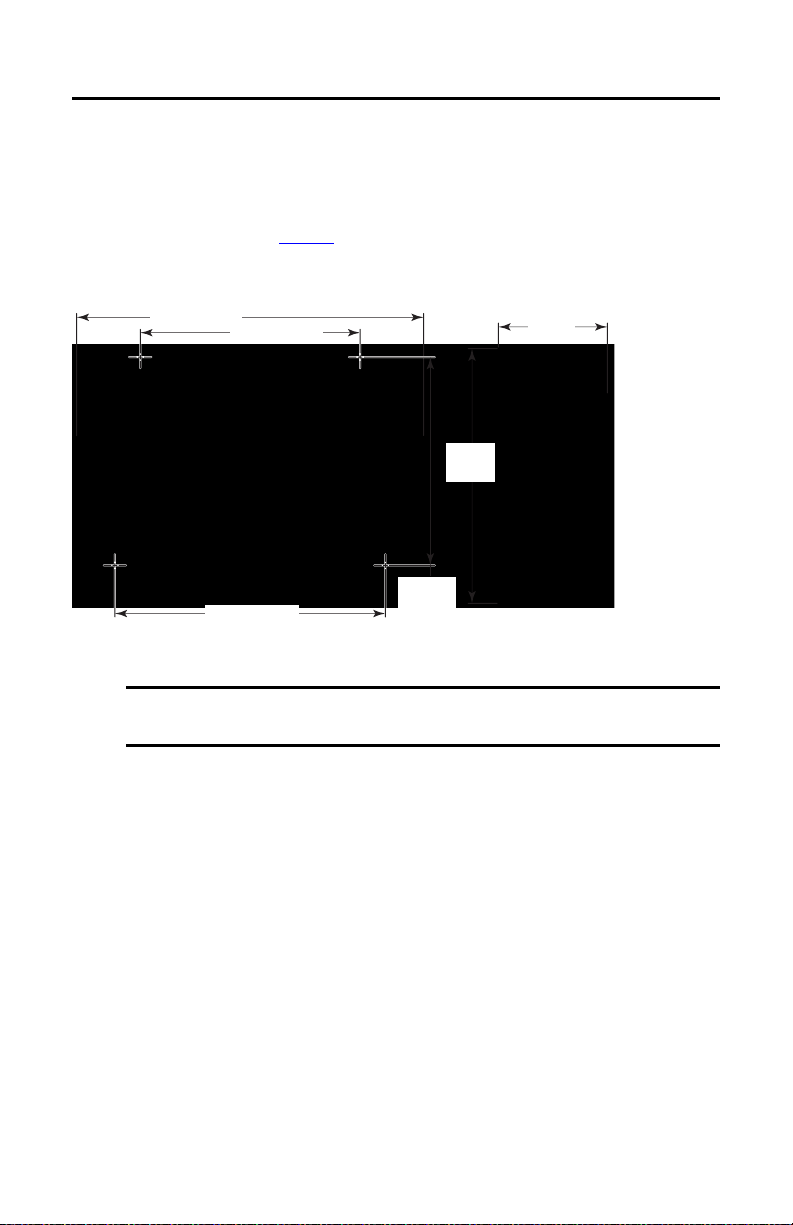
132.5 mm
(5.22 in.)
140 mm (5.5 in.)
70 mm
(2.76 in.)
210 mm (8.27 in.)
172 mm (6.77 in.)
160 mm
(6.3 in.)
The following instructions also apply to the back cover plate accessory.
To mount the back plate of an IP65 junction box, perform the following steps.
1. Determine where to mount the junction box.
Use the dimensions in Figure 4
to decide where to locate the junction box in a safe area
that is easily accessible for a terminal operator.
Figure 4 - IP65 Junction Box Dimensions (for 2711T-JBIP65DC1 and 2711T-JBIP65DM1)
2. Use the back plate or the supplied cutout template to mark where to drill the four
mounting holes for the junction box.
IMPORTANT Take precautions so metal cuttings do not enter components already installed in
the control cabinet or in the junction box.
3. With a drill and drill bit, drill the four holes.
TIP Use four M4 bolts with a maximum bolt head diameter of 9 mm, and with
self-locking M4 nuts.
However, the fasteners depend on the material of the mounting surface, such as
the wall of a control cabinet or a machine.
4. Attach the back plate to the mounting surface.
14 Rockwell Automation Publication 2711T-QS002D-EN-P - March 2021
Page 15

Second Generation MobileView Tethered Operator Terminal
IP65
Junction Box
Longer
Screw
Boss
Longer Screw Boss
Mounted
Back Plate
Temporarily Mount the IP65 Junction Box
Temporarily mount an IP65
junction box to its installed back
plate for the following:
• For hands-free wiring and
subsequent config uring of
2711T-JBIP65DC1, the
IP65 junction box with
cord grips
•For Box ID configuring
and brightness setting of
2711T-JBIP65DM1, the
IP65 junction box with
M12 On-Machine
connections
You can slide the IP65 junction box onto the longer screw bosses of the mounted back plate; no
screws are needed.
Wire the 2711T-JBIP65DC1 Junction Box
To wire the 2711T-JBIP65DC1 junction box, perform the following steps.
SHOCK HAZARD: When the back plate is removed, the circuit board inside the junction box is
sensitive to electrostatic discharge (ESD).
Use an antistatic wriststrap connected to the work surface, and properly grounded tools and
equipment.
1. See Figure 5 on page 16
to determine the appropriate cable outlets for the wires to be
installed.
2. Remove the cable glands from the cable outlets at the bottom of the junction box that
you plan to use.
3. With a small flat head screwdriver, remove the black plugs from the seal rings that you
plan to use.
Rockwell Automation Publication 2711T-QS002D-EN-P - March 2021 15
Page 16

Second Generation MobileView Tethered Operator Terminal
Item
No.
Cable Outlet
Description
Gland
Size Cable Dia. Range
Protection
Class
1 Standard M16 x 1.5 4…10 mm
(0.16…0.4 in.)
IP68
2Standard
3 Ethernet M 20 x 1.5 3…6 mm
(0.12…0.24 in.)
IP66
4Ethernet
5 Standard M16 x 1.5 4…10 mm
(0.16…0.4 in.)
IP68
6Standard
1
2
6
5
3
4
Black Plug
Cable Gla nd
1
2 3
54
6
Figure 5 - 2711T-JBIP65DC1 Junction Box Cable Outlets (with cover plate removed)
4. Place the corresponding seal rings over each wire.
5. Place the corresponding cable gland over each wire.
6. Feed each wire through the corresponding cable outlet.
7. See page 17
8. After all wires are attached, hand-tighten the cable glands to secure the wires.
for where to attach each wire to the appropriate terminal.
IMPORTANT To maintain the protection class, any unused cable outlet must be sealed with a
16 Rockwell Automation Publication 2711T-QS002D-EN-P - March 2021
black plug.
Page 17

Second Generation MobileView Tethered Operator Terminal
1
2
2
3
9. Before you reinstall the junction box to its back plate, consider how you plan to use the
junction box with a second generation MobileView terminal.
If Then
You plan to use a second generation MobileView term inal
that does not have Box ID functionality
You plan to use a second generation MobileView term inal
with Box ID functionality with multiple IP65 junction
boxes
You want to adjust the brightness of the illuminated Estop button on a second generation MobileView terminal
You must activate a DIP switch; see DIP Switch
You can assign an address for each junction box specific to
its application; see BoxID Functionality
You can press an adjustment button for four possible
brightness levels; see Illuminated E-stop Button
Brightness on page 21.
on page 20.
on page 20.
10. After you perform any suggestions in step 9, use a Torx 10 screwdriver and the six screws
to reinstall the junction box to its cover plate.
Item
1S16
2 ETH3, ETH2
3S10
PCB
Description Description
11-pin terminal for power, and safety circuits of E-stop push button and enabling switch of the
MobileView 2711T terminal. For more details, see S16 Terminal Pin Descriptions
8-pin, RJ45 terminal for Ethernet connectivity to a control system network. Use one terminal for
input and the other terminal for output. For more details, Ethernet (ETH3, ETH2) Connections
page 18.
6-pin terminal for an application or control system where multiple IP65 junction boxes are used.
This terminal helps identify which IP65 junction box has a second generation MobileView
terminal attached to it. For more details, S10 Terminal Pin Descriptions
on page 18.
on
on page 19.
Rockwell Automation Publication 2711T-QS002D-EN-P - March 2021 17
Page 18

Second Generation MobileView Tethered Operator Terminal
Pin No.
PCB
Description Description
1 N.C. Not connected
2 ZT2- Enabling device, circuit 2-
3 ZT1- Enabling device, circuit 1-
4 ZT2+ Enabling device, circuit 2+
5 ZT1+ Enabling device, circuit 1+
6 ES2 Emergency stop (E-stop), circuit 2
7 ES1 E-stop, circuit 1
8 ES2 E-stop, circuit 2
9 ES1 E-stop, circuit 1
10 – Ground (GND)
11 +
24V DC power supply
(see Power S upply
on page 5)
18
Pin # Ethernet Signal Pin # Ethernet Signal
1TD+ 5Not used
2TD- 6RD-
3RD+ 7Not used
4 Not used 8 Not used
S16 Terminal Pin Descriptions
Ethernet (ETH3, ETH2) Connections
Second generation MobileView 2711T terminals are equipped with an Ethernet interface that
supports TCP/IP protocol at 10/100 Mbps for half/full-duplex communication.
ATT EN TI ON : Under high noise situations, the Ethernet network can have packet loss of <10% at
100 Mbps. By design, Ethernet communication resends packets, so there is no data loss but there
is a possible reduction in communication speed.
The two Ethernet connectors on the IP65 junction box provide connection to an Ethernet
network. Each connector uses an 8-pin, RJ45 modular jack connector. Pinouts are as follows.
18 Rockwell Automation Publication 2711T-QS002D-EN-P - March 2021
Page 19

Second Generation MobileView Tethered Operator Terminal
Pin No. PCB Description Description
1 D RY Clos ed when a secon d gener ation M obileVi ew termi nal
is connected.
When an application or control system has multiple
IP65 junction boxes available, this I/O is used to
determine which junction box has a second generation
MobileView terminal connected to it.
2DRY
3KEY3
Not used.
4KEY2
5KEY1
6KEY0
1
2
3
S10 Terminal Pin Descriptions
IMPORTANT The DRY contact signal can be used in the control application and is only designed for
purposes that are not safety related.
Configure the 2711T-JBIP65DC1 Junction Box
The 2711T-JBIP65DC1 junction box can be configured to work with second generation
MobileView terminals with Box ID functionality and illuminated E-stop buttons.
Figure 6 - IP65 Junction Box Configurable Components
PCB
Item
Description Description
1 B4 A DIP switch meant for MobileView terminals without
2 BOX ID Two address switches to set the address when Box ID functionality is available on a MobileView
3 ADJUST Use this switch to set the brightness of the illuminated E-stop button on a second generation
switch if the MobileView terminal has an illuminated E-stop button. For more details, see DIP
Switch on page 20.
terminal. For more details, see BoxID Functionality
MobileView terminal. For more details, see Illuminated E-stop Button Brightness
Rockwell Automation Publication 2711T-QS002D-EN-P - March 2021 19
Box ID functionality. Activate this DIP
on page 20.
on page 21.
Page 20

Second Generation MobileView Tethered Operator Terminal
DIP Switch
If a MobileView terminal does not have Box ID functionality, then use this DIP switch to
configure whether or not an illuminated E-stop button is used on the MobileView terminal.
If Then
The MobileView terminal to be used has no Box ID
functionality and no illuminated E-stop button (such as
MobileView terminals with gray push buttons, cat. nos.
2711T-F10G1N1 and 2711T-T10G1N1)
All DIP switches must be
deactivated (factory set as
standard)
The MobileView terminal to be used has no Box ID
functionality but has an illuminated E-stop button
Activate DIP switch 8
IMPORTANT If the MobileView terminal being used has Box ID functionality and an illuminated E-stop
button, then no action is needed. The IP65 junction box automatically detects the
illuminated E-stop button, and all factory set DIP switch settings remain deactivated.
BoxID Functionality
If you have a second generation MobileView terminal with Box ID functionality, then you can
set an address on the IP65 junction box. With an address, only settings specific to that
application are available on the MobileView terminal. Use the two address switches whenever
one MobileView terminal with Box ID functionality is used between multiple IP65 junction
boxes in various locations. With the two address switches, you can set Box IDs from 0 to 255 as
hexadecimal values.
To use Box ID functionality with FactoryTalk® View ME software, access the Rockwell
Automation Knowledgebase link at https://rockwellautomation.custhelp.com/
AID 1043633.
Table 1 - Address Examples
Left Address
Switch
(1) Factory set as standard.
Right Address
Switch
00 0
0 F 15 A F 175
1 0 16 F 0 240
1 F 31 F F 255
MobileView
Ter mina l Ad dre ss
(1)
Left Address
Switch
Right Address
Switch
A0 160
and search for
MobileView
Ter mina l Ad dre ss
20 Rockwell Automation Publication 2711T-QS002D-EN-P - March 2021
Page 21

Second Generation MobileView Tethered Operator Terminal
Illuminated E-stop Button Brightness
You can use a button on the IP65 junction box terminal to adjust the
illuminated E-stop push button on a second generation MobileView
terminal.
WARNING: To adjust the brightness, power must be applied to the IP65 junction box, and a
second generation MobileView terminal must be connected to the junction box.
To avoid ESD damage to the junction box and to avoid electrical shock to the adjuster, only
qualified personnel should perform this adjustment.
The following brightness levels can be selected.
• 95% (factory setting) • 25%
• 50% • 12.5%
Each press of the button moves to the next brightness level. After you reach 12.5% brightness,
the next press cycles back to 95%.
IMPORTANT Only adjust the brightness level of the illuminated E-stop button if it is appropriate for the
environment where the second generation MobileView terminal is being used. Too low of a
brightness setting can be difficult to see or can be misinterpreted.
The set brightness level is maintained, even after a power loss.
Configure the 2711T-JBIP65DM1 Junction Box
The 2711T-JBI65MI junction box with M12 On-Machine connections is factory wired. It is still
shipped with the back plate removed, so you can configure Box ID functionality or adjust the
brightness of the illuminated push button on the MobileView terminal before you mount the
junction box to its back plate and connect the M12 On-Machine connections.
SHOCK HAZARD: When the back plate is removed, the circuit board inside the 2711T-JBIP65DM1
junction box is sensitive to electrostatic discharge (ESD).
Use an antistatic wriststrap connected to the work surface, and properly grounded tools and
equipment.
Box ID Functionality
See Figure 6 on page 19 for where to find the Box ID address switches on the junction box circuit
board.
See page 20
for how to configure Box ID functionality for your 2711T-JBI65MI junction box.
Rockwell Automation Publication 2711T-QS002D-EN-P - March 2021 21
Page 22

Second Generation MobileView Tethered Operator Terminal
Item
No.
Connector
Description M 12 Connector Type
1 Ethernet I/O D-code pin female
2 Dr y contact 5 pin micro-styl e male
3 Enabling device 5 pin I/O male
4 Control power Mini 4 pin male
5E-stop 5 pin I/O male
1
2
3
5
4
1
Illuminated E-stop Button Brightness
See Figure 6 on page 19 for where to find the illuminated E-stop button on the junction box
circuit board.
See page 21
for how to set the brightness of a second generation MobileView terminal meant to
attach to your 2711T-JBI65MI junction box.
Mount the IP65 Junction Box to Its Back Plate
To mount an IP65 junction box to its back plate,
perform the following steps.
1. If you temporarily mounted the IP65
junction box as detailed in Tem p o r a ri ly
Mount the IP65 Junction Box on page 15,
remove the junction box from the screw
bosses.
2. Align the IP65 junction box with its
mounted back plate.
IMPORTANT To maintain a tight seal and the IP65 rating, verify that the junction box is seated
properly to the cover plate.
3. Mount the junction box to its back plate with the six supplied screws.
Torque the six screws to 0.85…1.15 N•m (7.5…10.2 lb•in).
Connect M12 On-Machine Connectors to the 2711T-JBIP65DM1 Junction Box
To connect M12 On-Machine connectors to the 2711T-JBIP65DM1 junction box, perform the
following steps.
1. Determine where to connect each M12 On-Machine connection.
22 Rockwell Automation Publication 2711T-QS002D-EN-P - March 2021
Page 23

Second Generation MobileView Tethered Operator Terminal
Pin
No. Des cription Wire Color
8-way
Modular
RJ45 Pin
1 M12_Tx+ White-orange 1
2 M12_Rx+ White-green 3
3 M12_Tx– Orange 2
4 M12_Tx– Green 6
5 Connector shell shield GND
4
1
2
3
5
3
21
4
5
Pin
No. Description
1Output power +
2Sensor/MDL power +
3Sensor/MDL power –
4Output power –
4
12
3
M12 Ethernet Pin Descriptions
For the D-code M12 female network connectors, use polyamide small-body unshielded or zinc
die-cast large-body shielded mating connectors.
If you use shielded (STP) cable with metal housing, isolate the shield at the junction box end of
the cable to minimize ground offsets.
M12 Dry Contact, E-stop, and Enabling Device Pin Descriptions
Pin
M12 Dry Contact
No.
Pin Descriptions
1 External 24V input 1 E-stop 2 test output 1 Enabling device 2 test output
2— 2E-stop 2 safe input 2Enabling device 2 safe input
3 Ground (GND) 3 — 3 —
4 Dry contact output 4 E-stop 1 safe input 4 Enabling device 1 safe input
5 — 5 E-stop 1 test out put 5 Ena bling device 1 test output
Pin
No.
M12 E-stop
Pin Descriptions
Pin
M12 Enabling Device
No.
Pin Descriptions
M12 Power Pin Descriptions
Rockwell Automation Publication 2711T-QS002D-EN-P - March 2021 23
Page 24

Second Generation MobileView Tethered Operator Terminal
Connect Power to IP65 Junction Boxes
After an IP65 junction box has been mounted, configured, and wired or connected, apply power
to the junction box.
For information on 24V DC power supply requirements, see Power Supply
SHOCK HAZARD: Supply the IP65 junction box and the second generation MobileView terminal
exclusively from power sources with SELV or PELV circuit protection according to EN 61131-2.
Only connect voltages and circuits that are separated from dangerous voltages (for example, by
means of sufficient insulation) to connections, terminals or interfaces up to a rated voltage of
50V DC.
After power has been applied, perform the following steps to verify that the IP65 junction box is
performing correctly.
IMPORTANT See Table 2 on page 25 for what the following colors represent.
1. Verify that the power status indicator on the front of the IP65 junction box is lit and
green in color.
2. Verify that the Ethernet status indicator on the front of the IP65 junction box is lit and
green in color.
3. Connect a second generation MobileView terminal.
a. If the MobileView terminal has an illuminated E-stop button, verify that the
illuminated
E-stop status indicator on the front of the IP65 junction box is lit and green in color.
b. Verify that the status indicator bar on the front of the IP65 junction box is lit and
solid green in color.
4. Push the illuminated E-stop push button on the second g eneration MobileView terminal
to trigger a stop.
Verify that the status indicator bar on the front of the IP65 junction box is lit and solid
red in color.
5. Disconnect the MobileView terminal.
on page 5.
IMPORTANT When you disconnect a second generation MobileView terminal from an IP65
junction box, it begins a 10-second countdown to a system emergency stop.
Therefore, you have 10 seconds to reconnect a second generation MobileView
terminal or black bridge connector to keep the safety circuit complete.
a. Verify that the status indicator bar on the front of the IP65 junction box changes
from solid red to solid yellow.
b. Verify that the status indicator bar reduces one blinking yellow light after each 1.67
seconds of disconnect time.
24 Rockwell Automation Publication 2711T-QS002D-EN-P - March 2021
Page 25

Second Generation MobileView Tethered Operator Terminal
Power
Illuminated
E-stop
Status Indic ator
Bar
Ethernet
IMPORTANT Only perform step c if you are commissioning the unit, performing
maintenance, or testing safety equipment, because step c triggers a system
emergency stop.
c. After 10 seconds of disconnect time, verify that all six lights of the status indicator
bar are off and subsequently replaced by a blinking yellow status indicator bar.
The blinking yellow status indicates that the relay outputs of the IP65 junction box
are de-energized and therefore open, which triggers an emergency stop of the system
or machine.
WARNI NG: An IP65 junction box does not protect against the restart of a system or
machine. Separate protection must be provided on the system or machine, such as
an Acknowledgment key.
IP65 Junction Box Status Indicator Lights
The front of each IP65 junction box has three status indicators and a status indicator bar.
explains what each color signifies on the lights and status indicator bar.
Ta b l e 2
Table 2 - IP65 Junction Box Status Indicators and Bar Colors
Indicator Color Displayed Status Indicated
Power Green Power is present and the IP65 junction box is ready for operation.
No color No power is present or there is a fault during startup.
Illuminated
E-stop
Green A second generati on MobileView terminal with an ill uminated E-stop button is connec ted
No color A second generation MobileView terminal without an illuminated E-stop button is
to the junction box.
connected to the junction box.
Rockwell Automation Publication 2711T-QS002D-EN-P - March 2021 25
Page 26
Second Generation MobileView Tethered Operator Terminal
Table 2 - IP65 Junction Box Status Indicators and Bar Colors (Continued)
Indicator Color Displayed Status Indicated
Ethernet Green The junction box is connected to an Ethernet network.
No color The junction box is not connected to an Ethernet network.
Status indicator
(1)
bar
(1) The IP65 junction box must have power (green at power status indicator) for the status bar to display status.
Solid green A second generation MobileView terminal with an E-stop button is connected correctly
Solid white No second generation MobileView terminal is connected but a 22-pin bridge connector is
Blinking white No second generation MobileView terminal or 22-pin bridge connec tor is connected to the
Solid yellow Begins the disconnect count time of 10 seconds after a second generation MobileView
Partial yellow Going from right to left, a light on the status bar shuts off after 1.67 seconds of disconnect
Blinking yellow When no plug is connected after 10 seconds, the disconnect timeout forces the junction
Solid red An E-stop button on a second generation MobileView terminal has been pressed and safe
and the E-stop has not been pressed.
connected correctly.
junction box.
terminal or 22-pin bridge connector is disconnected from the junction box.
time has passed. For example, only three of the six lights remain lit after five seconds of
disconnect time.
box into a safe mode.
mode is activated.
ATTENTION: Other colors signify when a second generation MobileView terminal or IP65 junction
box are in an error state. To identify these colors, see the Troubleshooting section in the
MobileView Tethered Operator Terminal User Manual, publication 2711T-UM001.
Reconnect Power to IP65 Junction Boxes
If the IP65 junction box is powered off, the relays of the emergency stop circuits are no longer
actively held closed and the emergency stop circuit is subsequently opened, which is comparable
to an activated E- stop.
When powered off, the input states and E-stop state at that time are saved in the IP65 junction
box memory. When power is restored, these saved states are subsequently retrieved.
Therefore, the IP65 junction box can have the following states.
State Description
Normal A second generation MobileView terminal (with an unactivated E-stop push button) is connected.
26 Rockwell Automation Publication 2711T-QS002D-EN-P - March 2021
Page 27

Second Generation MobileView Tethered Operator Terminal
State Description
Bride active A black, 22-pin bridge connector is connected.
E-stop The E-stop push button on the second generation MobileView terminal has been activated.
The E-stop push button on the connected, second generation MobileView terminal and the retrieved E-stop
Error state
in the IP65 junction box memory are not the same. In this case, the E-stop push button of the connected
MobileView terminal is unactivated but the saved, retained E-stop in the IP65 junction box memory is
activated. Therefore, the E-stop push button on the MobileView terminal must be activated and then
unlocked to reset the IP65 junction box.
Connected/Disconnected Timer State
A second generation MobileView terminal or a black bridge connector must be connected to the
IP65 junction box. When you disconnect one to connect the other, the IP65 junction box
recognizes the disconnection and enters a timer state, when the operator has a maximum of 10
seconds to reconnect a device.
During this disconnected time, the E-stop of the IP65 junction box is bypassed until a
MobileView terminal with an unactivated E-stop push button or a black bridge connector is
connected.
If Then
The connected, second generation MobileView terminal
has an illuminated E-stop push button that is
(1)
unactivated
The connected, second generation MobileView terminal
has an illuminated E-stop push button that is properly
configured but activated
A black bridge connector is being connected The black bridge connec tor must be connected within 10 seconds for
No second generation MobileView terminal or black
bridge connector is connected within 10 seconds
(1) You must first configure an IP65 junc tion box to recognize an illuminated E-stop push button on a second generation MobileView terminal. For
more information, see DIP Switch
on page 20.
The E-stop push button is recognized by the IP65 junction box and it
is illuminated.
The E-stop push button on the second generation MobileView
terminal must be deactivated and reset before the IP65 junction box
returns to the normal state mentioned in Reconnect Power to IP65
Junction Boxes on page 26.
the IP65 junction box to recognize the device and enter the bridge
active state mentioned in Reconnect Power to IP65 Junction Boxes
page 26.
The IP65 junction box timer state times out and an E-stop is
triggered.
on
Rockwell Automation Publication 2711T-QS002D-EN-P - March 2021 27
Page 28

Second Generation MobileView Tethered Operator Terminal
57 mm (2.25 in)
Red dot on cable connector must align
with red dot on junction box.
Connect a Second Generation MobileView Terminal to an IP65 Junction Box
To power up or start a second generation MobileView 2711T terminal, insert a 22-pin
connection cable into the MobileView IP65 junction box. A 22-pin connection cable has a black
cable connector.
IMPORTANT You can use a 22-pin connection cable with all second generation MobileView terminals, first
generation MobileView terminals 2711T-F10G1N1 and 2711T-T10G1N1, and both IP65
junction boxes.
You cannot use a 22-pin connection cable with first generation MobileView terminals 2711TB10K1N1, 2711T-B10M1N1, and 2711T-T10R1N1, or an IP20 junction box.
Connect a Black Bridge Connector to an IP65 Junction Box
An optional black, 22-pin bridge connector (Cat. No. 2711T-22JUMP) is available for the IP65
junction box. It is for situations when the IP65 junction box is powered on but a second
generation MobileView terminal is not connected to the junction box.
In these situations, the black bridge connector is connected so the IP65 junction box is placed in
a bridge active state and its E-stop circuits are bypassed.
The black bridge connector includes a tethered cable so it can be secured with one of the bottom
screws of an IP65 junction box. For more information on the bottom screws, see Mount the I P65
Junction Box to Its Back Plate on page 22.
Connect to an Ethernet Network
Second generation MobileView 2711T terminals are equipped with an Ethernet interface that
supports TCP/IP protocol
The Ethernet connector on IP65 junction boxes provide a connection to an Ethernet network.
The connector uses an 8-pin, RJ45 modular jack connector.
To connect to an Ethernet network, see Ethernet (ETH3, ETH2) Connections
28 Rockwell Automation Publication 2711T-QS002D-EN-P - March 2021
at 10/100 Mbps for half/full-duplex communication.
on page 18.
Page 29

Second Generation MobileView Tethered Operator Terminal
Status Indicator Light
Start-up Screen
Initial Power Up of the Second Generation MobileView 2711T Terminal
This section applies to when you apply power to the second generation MobileView 2711T
terminal for the first time. It provides details on the following topics:
• Verify the Connection
• Test Safety Functions
• Initial Configuration of the Windows Operating System
• Icons on the Terminal Desktop Taskbar
Verify the Connection
To verify that the second generation MobileView 2711T terminal is properly connected,
perform the following steps.
1. Attach the 22-pin MobileView connection cable to the IP65 junction box as shown on
28.
page
ATTENTION: The second generation MobileView 2711T terminal automatically starts when the
22-pin connection cable is connected to an IP65 junction box with 24V DC power applied.
2. Check the second generation MobileView 2711T terminal for a start-up screen.
If the start-up screen does not appear, check the 24V DC power source and cable
connections at the IP65 junction box and second generation MobileView 2711T
terminal.
Rockwell Automation Publication 2711T-QS002D-EN-P - March 2021 29
Page 30

Second Generation MobileView Tethered Operator Terminal
IMPORTANT If the second generation MobileView 2711T terminal is properly connected to the IP65
junction box, a status indicator light on the terminal next to the E-stop is illuminated
green.
When a second generation MobileView 2711T terminal is powered up, a dark screen is
present for several seconds between the start-up screen and the next available screen.
Test Safety Functions
To test the safety functions of the second generation MobileView 2711T terminal, perform the
following steps.
1. Connect the safety terminations for the E-stop and 3-position enable switch to the IP65
junction box.
2. Apply power to the IP65 junction box.
3. Attach the 22-pin MobileView connection cable to the IP65 junction box as shown on
28.
page
4. Test the E-stop push button and the enabling switch to verif y that each safety function is
operating properly. Verify that the machine or plant operation stops when the button is
pushed.
30 Rockwell Automation Publication 2711T-QS002D-EN-P - March 2021
Page 31

Second Generation MobileView Tethered Operator Terminal
Onscreen Keyboard
Initial Configuration of the Windows Operating System
When a second generation MobileView 2711T terminal is powered up for the first time, several
setup messages appear:
• Setup is starting services
• Setup is installing devices
• Setup is applying system settings
• Setup will continue after restarting your computer
The terminal then reboots. After the start-up screen appears, another setup message appears:
• Setup is preparing your computer for first use
This message begins the Windows End User Setup procedure.
IMPORTANT Do not disconnect power from the second generation MobileView 2711T terminal until after
the Windows End User Setup procedure is completed.
If power is disconnected during this procedure, it can result in a corrupted system image.
To configure the Windows operating system on the second generation MobileView 2711T
terminal, perform the following steps.
1. Enter the appropriate information to the screen that prompts you to create an
administrator account and a computer name.
IMPORTANT When you touch a data field in a dialog box, an onscreen keyboard appears so that
you can type in your information. You can also connect and use an extern al keyboard
through the USB port on the back of the terminal.
2. After you add information, press Next.
Rockwell Automation Publication 2711T-QS002D-EN-P - March 2021 31
Page 32

Second Generation MobileView Tethered Operator Terminal
3. Enter your account password into the next screen.
TIP An account password is recommended but not mandatory; if you do not want one,
press Next.
4. After you add information, press Next.
A license-terms dialog box appears. The license terms apply to Microsoft® Windows®
Embedded Standard 7 operating system and all Allen-Bradley software content.
5. Press to check the ‘I accept the licensed terms’ box, and press Next.
32 Rockwell Automation Publication 2711T-QS002D-EN-P - March 2021
Page 33

Second Generation MobileView Tethered Operator Terminal
6. Choose your appropriate date and time settings, and press Next.
A pop-up dialog box appears, ‘Windows is finalizing your settings.’
When completed, the second generation MobileView 2711T terminal desktop appears.
Rockwell Automation Publication 2711T-QS002D-EN-P - March 2021 33
Page 34

Second Generation MobileView Tethered Operator Terminal
Icons on the Terminal Desktop Taskbar
The icons on the terminal desktop taskbar serve the following functions.
Button Description
Press to power down the second generation
Press to reboot (restart) the second generation
Press to toggle between open tasks and applications on the second generation
(similar to Alt+Tab on a keyboard).
Status indicator for Enhanced Write Filter (EWF).
Closed lock signifies EWF is enabled and open lock signifies EWF is disabled.
MobileView 2711T terminal.
MobileView 2711T terminal.
MobileView 2711T terminal
Initial Configuration of MobileView Application Settings
Enhanced Write Filter (EWF)
The Enhanced Write Filter (EWF) is a feature within the operating system of the second
generation MobileView 2711T terminal. When EWF is enabled, the system volume within the
operating system is write-protected, which provides an additional level of robustness for the
operating system.
Before you configure applications on the second generation MobileView 2711T terminal, verify
that EWF is disabled. On the terminal desktop taskbar, the EWF status icon is unlocked
when EWF is disabled.
IMPORTANT By default, EWF is disabled. EWF must be disabled or any application changes are lost when
the second generation MobileView 2711T terminal is powered down.
Rockwell Automation recommends that you enable EWF to preserve operating system and
application integrity, especially for where the terminal is expected to be frequently connected
and disconnected from junction boxes.
Rockwell Automation recommends that you only enable E WF after applications on the second
generation MobileView 2711T terminal such as FactoryTalk® View Machine Edition (ME) have
been set up.
EWF applies only to the internal storage drive (C:) of the second generation MobileView 2711T
terminal and not to the internal Secure Digital (SD) card drive (D:).
34 Rockwell Automation Publication 2711T-QS002D-EN-P - March 2021
Page 35

Second Generation MobileView Tethered Operator Terminal
To enable EWF, perform the following steps.
1. On the terminal desktop taskbar, verify that the EWF is unlocked.
EWF is enabled if the status icon is locked ; EWF is disabled if the status icon is
unlocked .
2. On the second generation MobileView 2711T terminal desktop, press the EWF
Manager.
3. The following screen appears. Press OK.
If you change the EWF status, then the second generation MobileView 2711T terminal
automatically restarts.
4. When the terminal desktop reappears, the EWF status icon on the terminal desktop
taskbar is locked to signify EWF is enabled.
By default, EWF is disabled.
IMPORTANT
Rockwell Automation Publication 2711T-QS002D-EN-P - March 2021 35
Rockwell Automation recommends that you only enable EWF after applications on
the
second generation
software have been set up.
If you make application changes with EWF enabled, then those changes are lost
when the second generation MobileView 2711T terminal is powered down or
reboote d.
MobileView 2711T terminal such as FactoryTalk View ME
Page 36

Second Generation MobileView Tethered Operator Terminal
Network Settings
To configure the Ethernet communications of your second generation MobileView 2711T
terminal, perform the following steps.
1. On the second generation MobileView 2711T terminal desktop, press Network Settings.
The Local Area Connection icon appears with the network cable unplugged.
TIP You can also press Control Panel>Network and Internet>Network Connections to
access the same screen.
2. Touch and hold for about 3 seconds, and then release.
A pull-down menu appears.
3. Press Properties.
4. On the Properties dialog box, press to select Internet Protocol Version 4 (TCP/IPv4).
5. Press Properties.
36 Rockwell Automation Publication 2711T-QS002D-EN-P - March 2021
Page 37

Second Generation MobileView Tethered Operator Terminal
Must be a unique address on the LAN.
Must be identical to the server subnet mask.
Optional
6. On the General tab of the Properties dialog box, press one of the following buttons:
• ‘Obtain an IP address automatically’ if you have a DHCP server on your network
that assigns IP addresses to the second generation MobileView 2711T terminal.
• ‘Use the following IP address’ to assign a static IP address. Complete the three text
boxes with information from your network administrator or Internet service
provider.
Use the onscreen keyboard or an external keyboard to enter the text.
7. Press OK.
8. Press Close on the Local Connection Properties dialog.
9. Close Network Connections window to return to the second generation MobileView
2711T terminal desktop.
FTView ME Station
FactoryTalk View Machine Edition (ME) Station software on your second generation
MobileView 2711T terminal is dependent on a runtime application file that is configured on a
separate personal computer with FactoryTalk View Studio software installed.
IMPORTANT EWF must be disabled before you configure FactoryTalk View ME settings, and then enabled
afterwards. For more information, see Enhanced Write Filter (EWF)
To initially configure FactoryTalk View ME Station, perform the following steps.
1. Create a runtime application file (MER) with FactoryTalk View Studio software.
2. Within FactoryTalk View Studio software, launch the transfer utility.
Rockwell Automation Publication 2711T-QS002D-EN-P - March 2021 37
on page 34.
Page 38

Second Generation MobileView Tethered Operator Terminal
A
B
C
D
3. On the Download tab of the Transfer Utility dialog box, select the following:
• The MER file that you just created on your personal computer as the source file (A).
• The destination storage type as External Storage 1 (B). This selection places the
MER file on the SD card of your second generation MobileView terminal.
• Select your second generation MobileView terminal as the destination terminal (C).
• Click Download (D).
TIP See the graphic with step 6 on page 39 to view the MER file location on the SD card.
4. On the second generation MobileView 2711T terminal desktop, press FTView ME
Station.
38 Rockwell Automation Publication 2711T-QS002D-EN-P - March 2021
Page 39

Second Generation MobileView Tethered Operator Terminal
This dialog appears.
5. Press Load Application or F1 to load the MER file.
6. Browse to the internal SD card drive (D:) and press the MER file that you wish to load.
7. Press Open.
You are prompted if you wish to replace the current communication configuration of the
terminal with the communication configuration of the application.
8. Depending on your application, press Yes or No.
Wait while the application loads.
9. Press Terminal Settings or F4 to configure FactoryTalk ME Station-specific settings (for
example, for FactoryTalk View ME Station to automatically start on a MobileView
2711T terminal power up or reboot).
10. If desired, press Application Settings or F3 to configure FactoryTalk View ME Station
application-specific settings (for example, device shortcuts or start-up language).
Rockwell Automation Publication 2711T-QS002D-EN-P - March 2021 39
Page 40

Second Generation MobileView Tethered Operator Terminal
11. Press the second generation MobileView terminal desktop to access EWF Manager and
enable EWF; see page 34 for how to enable EWF.
IMPORTANT Do not press the Exit button (F8) in FactoryTalk View ME Station before you access
EWF Manager on the MobileView terminal desktop.
After you enable EWF, the MobileView 2711T terminal automatically restarts.
12. If FactoryTalk View ME Station was configured in step 9 to automatically start after any
second generation MobileView 2711T terminal startup or reboot, then the application
automatically starts after step 11
If FactoryTalk was not configured to automatically start, then you must press the
FactoryTalk View ME Station icon on the second generation MobileView terminal
desktop to load and run the application.
.
Right-click Touch Screen Functionality and FactoryTalk View ME Station
If your FactoryTalk View ME Station uses momentary push buttons and you require long press
times to activate those buttons, then the right-click touch screen functionality within the
MobileView operating system must be disabled. By default, right-click functionality is enabled
for the touch screen.
IMPORTANT EWF must be disabled before you change right-click functionality, and then enabled
afterwards. For more information, see Enhanced Write Filter (EWF)
To disable right-click touch screen functionality, perform the following steps.
1. From the second generation MobileView 2711T terminal desktop, press Touch
Configuration.
40 Rockwell Automation Publication 2711T-QS002D-EN-P - March 2021
on page 34.
Page 41

Second Generation MobileView Tethered Operator Terminal
2. On the Touch tab of the Pen and Touch dialog box, press Press and hold.
With Press and hold highlighted, press Settings.
3. Clear the Enable press and hold for right-clicking checkbox.
4. Press OK.
Rockwell Automation Publication 2711T-QS002D-EN-P - March 2021 41
Page 42

Second Generation MobileView Tethered Operator Terminal
5. On the Touch tab, press Apply.
Right-click functionality for the touch screen is now disabled.
6. Enable EWF to save your settings. For more information, see Enhanced Write Filter
(EWF) on page 34.
Shut Down the Second Generation MobileView 2711T Terminal
To shut down the second generation MobileView 2711T terminal, perform the following steps.
IMPORTANT If you disabled EWF to make application changes, then you must enable EWF again before your
shut down the second generation MobileView 2711T terminal.
Review Enhanced Write Filter (EWF)
MobileView 2711T terminal.
1. Close FTView ME Station and return to the second generation MobileView terminal
desktop.
2. Press on the desktop taskbar to shut down the second generation MobileView
2711T terminal.
3. Press OK on the shutdown confirmation dialog box.
The terminal shuts down.
42 Rockwell Automation Publication 2711T-QS002D-EN-P - March 2021
on page 34 before you shut down the second generation
Page 43

Second Generation MobileView Tethered Operator Terminal
VESA Mounting Bracket
(cat. no. 2711T-VMBRACKET)
Standard Mounting Bracket
(cat. no. 2711T-BRACKET)
365 (14.4)118 (4.6)200 (7.9)
393 (15.5)
453 (17.8)
161 (6.3)
171 (6.7)
All dimensions are in mm (in.)
4. If desired, you can disconnect the tethered cable from the MobileView IP65 junction
box.
IMPORTANT Do not disconnect the tethered cable from the MobileView IP65 junction box until you first
shut down the second generation MobileView 2711T terminal.
See publication 2711T-UM001, MobileView 2711T Tethered Operator Terminal User Manual,
for more information on the various ways to shut down and power off the terminal.
MobileView Mounting Brackets
There are two mounting brackets available for second generation MobileView terminals. Both
mounting brackets are an accessory, which means they must be ordered separately from the
second generation MobileView 2711T terminal.
The MobileView standard mounting bracket (Cat. No. 2711T-BRACKET) is used for
stationary operation or storage of the terminal. The MobileView VESA® mounting bracket (Cat.
No. 2711T-VMBRACKET) connects to the back of the MobileView terminal, so the terminal
can be mounted, stored, and locked into the bracket. This bracket is when locked storage is
preferred.
Each mounting bracket ships with a cutout template for installation; 2711T-DS001
standard mounting bracket and 2711T-DS003
for the VESA mounting bracket.
Figure 7 - MobileView Terminal Mounting Brackets
All dimensions are in mm (in.)
200 (7.9) 161 (6.3)
118 (4.6) 365 (14.4)
with the
171 (6.7)
393 (15.5) 453 (17.8)
Rockwell Automation Publication 2711T-QS002D-EN-P - March 2021 43
Page 44

Second Generation MobileView Tethered Operator Terminal
European Communities (EC) Directive Compliance
Rockwell Automation hereby declares that second generation MobileView 2711T terminals
with E-stop functionality are in conformity with Directive 2006/42/EC as specified in the
Declaration of Conformity available from rok.auto/certifications
The second generation MobileView 2711T terminal and IP65 junction boxes have a CE mark
and are approved for installation within European Union and European Economic Area (EEA)
regions. The second generation MobileView 2711T terminal and IP65 junction boxes have been
designed and tested to meet the following directives.
EMC Directive
The second generation MobileView 2711T terminal and IP65 junction boxes are tested to meet
the Council Directive 2014/30/EU Electromagnetic Compatibility (EMC) by applying the
following standards, in whole or in part, which is documented in a technical construction file.
• EN 61131-2:2007–Programmable Controllers–Part 2: Equipment Requirements and
Tests (pertinent EMC sections)
• EN ISO 10218-1:2011–Robots and Robotic Devices–Safety Requirements for Industrial
Robots–Part 1: Robots (this standard applies only to the IP65 junction boxes)
The second generation MobileView 2711T terminal and IP65 junction boxes are intended for
use in an industrial environment.
.
ATTENTION:
61000-6-4:2011, Class A Emissions for Industrial Environments. In residential environments, this
product can cause high frequency inter ferences. If necessary, take corrective measures.
The
second generation
MobileView 2711T terminal meets the requirements of
Safety of Machinery Standards
The second generation MobileView 2711T terminal and IP65 junction boxes meet the following
machinery standards:
–
• EN ISO 13850:2015
Design
• EN 60204-1:2006+A1:2009–Safety of Machinery–Electrical Equipment of Machines
Part 1: General Requirements
In addition, the IP65 junction boxes meet the following machinery standards:
• EN ISO 13849-1:2015
Part 1: General Principles for Design
• EN 62061:2005+A1:2013+A2:2015
related Electrical, Electronic and Programmable Electronic Control Systems
A declaration of conformity (DoC) is available upon request or from rok.auto/certifications
44 Rockwell Automation Publication 2711T-QS002D-EN-P - March 2021
Safety of Machinery–Emergency Stop Function–Principles for
–
Safety of Machinery–Safety-related Parts of Control Systems
–
Safety of Machinery–Functional Safety of Safety-
–
.
–
Page 45

Second Generation MobileView Tethered Operator Terminal
Second Generation MobileView Terminal Specifications
General
Attribute 2711T-B10I1N1 2711T-T10I1N1-TC
Processor Intel Atom 3815, 1.46 GHz
Operating system Microsoft Windows Embedded Standard 7
Memory 4 GB DRAM/32 GB Flash
Display
Size (in.)
Color/resolution
Touch screen
Functi on keys Yes No
3-position enable switch Yes No
2-circuit E-stop Yes No
USB drive slot Yes
Communication 10/100 Ethernet
Dimensions See page
Weight 1550 g (3.42 lb) without options
Electrical
Attribute 2711T-B10I1N1 2711T-T10I1N1-TC
Rated supply voltage 24V DC
Supply voltage tolerance range 19.2…30V DC (EN 61131-2)
Input current 500 mA at 24V DC
Peak inrush current 5.6 A (max)
Cycl e dura tion
(1) Applies only to the connection cable connector and the junction box.
(1)
10.1
WXGA/1280 x 800 pixels
Analog resistive
3
5000 (typical)
Rockwell Automation Publication 2711T-QS002D-EN-P - March 2021 45
Page 46

Second Generation MobileView Tethered Operator Terminal
Environmental
Attribute 2711T-B10I1N1 2711T-T10I1N1-TC
Operating temperature
Storage temperature -25…+70 °C (-13…+158 °F)
Relative humidity
(noncondensing)
Vibration (operating) 5…150 Hz
Shock (operating) 15 G (1/2 Sine, 11 msec) IEC 60068-2-27
Operating altitude 0…2,0 00 m (0…6,562 ft)
(1) 0…50 °C (32…122 °F) temperature range is with typical device utilization of 100% CPU, display brightness at 50%, and GPU set to maximum
battery life.
When operating under full load, a derating of 5°C (9 °F) , absolute 45°C (113°F) must be taken into consideration.
See Adjust the Display Brightness and GPU Energy Setting in Ch apter 3 in the MobileView Tethe red Operator Terminal User Manua l, publication
2711T-UM001
If you need assistance in setting CPU and G PU ratings, contact your Rockwell Automation representative.
for information on adjusting these settings.for information on adjusting these settings.
0…50 °C (32…122 °F)
under full load.
5…95% at 0…45 °C (32…113 °F)
5…8.4 Hz, 3.5 mm p-p
8.4…150 Hz, 1 G peak
(1)
. The MobileView 2711T is UL rated for 0…45 °C (32…113 °F)
IP65 Junction Box Specifications
General
Cat. No. 2711T-
Attribute
USB drive slot Yes (2.0)
Communication 10/ 100 Ethernet
Dimensions See page 3
Weight, approx 500 g (1.1 lb)
JBIP65DC1 JBIP65DM1
Electrical
Cat. No. 2711T-
Attribute JBIP65DC1 JBIP65DM1
Rated supply voltage 24V DC
Supply voltage tolerance range 19.2…30V DC (EN 61131- 2)
Input current
(1)
46 Rockwell Automation Publication 2711T-QS002D-EN-P - March 2021
500 mA at 24V DC
Page 47

Second Generation MobileView Tethered Operator Terminal
Cat. No. 2711T- (Continued)
Attribute JBIP65DC1 JBIP65DM1
Peak inrush current 5.6 A (max)
Connector cycle duration
(2)
E-stop functions
•Voltage, min
•Current, min (Ie)
• Current carrying capacity, min
• Usage category
• Reaction time, max
•Isolation
• Bounce time
• Proof-test interval
• Switching cycles relay
•PFH
d
(1) Without a MobileView terminal conn ected to the junction box.
(2) Applies to black, 22-pin cable connector. Test the connector monthly to verify that it locks properly. Remove the IP65 junction
box from operation after the connection cycles have been exceeded.
(3) Reaction time is ti me before the E-stop is triggered.
(4) Decommission the safety function once the E-stop has been activated 250,000 times or after 20 years, whichever comes first.
(3)
(4)
5000 (typical)
• 5V DC per contact
• 10 mA per contact
• 1000 mA per contact
• DC-13 (IEC 60947-5-1)
• 19 ms
• 500V AC to rest
•<10 ms
• 20 years
5
• 10 x 10
-10
• 9.79 x 10
(1/h)
Rockwell Automation Publication 2711T-QS002D-EN-P - March 2021 47
Page 48

Second Generation MobileView Tethered Operator Terminal
IP65 Junction Box Specifications
(continued)
Environmental
Cat. No. 2711T-
Attribute JBIP65DC1 JBIP65DM1
Operating temperature 5…45 °C (41…113 °F)
Storage temperature -25… +70 °C (-13…+158 °F)
Relative humidity (noncondensing) 5...95% at 5…45 °C (41…113 °F)
Vibration (operating) 5…150 Hz
Shock (operating) 15 G (½ Sine, 11 msec) IEC 60068-2-27
Altitude 0…3,000 m (0…9,843 ft)
5…8.4 Hz, 3.5 mm p-p
8.4…150 Hz, 1 G peak
MobileView Accessories
Cat. No. Description
2711T-5MCABLE2 22-pin connection cable (5 m/16.4 ft) to connect the second generation terminal to the IP65 j unction box.
2711T-10MCABLE2 22-pin connection ca ble (10 m/32.8 ft) to connect the second generation terminal to the IP65 junction
2711T-15MCABLE2 22-pin connection ca ble (15 m/49.2 ft) to connect the second generation terminal to the IP65 junction
2711T-JBIP65DC1 A 24V DC powered, IP65 junction box with cord grips.
2711T-JBIP65DM1 A 24V DC powered, prewired IP65 junction box with metal connections.
2711T-JBBKCOVER A back cover accessory plate for the 2711T-JBIP65DC1 and 2711T-JBIP65DM1 junction boxes.
2711T-BRACKET Mounting bracket for stationary operation or to store the terminal.
2711T-VMBRACKET VESA mounting bracket for stationary operation or locked storage of the terminal.
2711T-22JUMP A black, 22-pin bridge connector to bypass E-stop contac tors in an IP65 MobileView junction box.
(1) For applications where the customer plans to m ove one MobileView terminal between many MobileView junction boxes.
box.
box.
(1)
48 Rockwell Automation Publication 2711T-QS002D-EN-P - March 2021
Page 49

Second Generation MobileView Tethered Operator Terminal
Additional Resources
These documents contain more information about related products from Rockwell Automation.
Resource Description
MobileView Tethered Operator Te rminal User Manual,
publication 2711T-UM001
FactoryTalk View Machine Edition User’s Guide,
publication VIEWME-UM004
Industrial Automation Wiring and Grounding
Guidelines, publication 1770-4.1
Product Certifications website, rok.auto/certifications
You can view or download publications at https://www.rockwellautomation.com/global/
literature-library/overview.page.
Provides information to install, operate, and troubleshoot MobileView
2711T terminals and junction boxes.
Provides comprehensive information about Fac toryTalk View Machine
Edition, procedures to create and run an automation application, and
reference information.
Provides general guidelines to install a Rockwell Automation industrial
system.
Provides declarations of conformity, certificates, and other certification
details.
Rockwell Automation Publication 2711T-QS002D-EN-P - March 2021 49
Page 50

Rockwell Otomasyon Ticaret A.Ş., Kar Plaza İş Merkezi E Blok Kat:6 34752 İçerenköy, İstanbul, Tel: +90 (216) 5698400
Rockwell Automation Support
Use the following resources to access support information.
Documentation Feedback
Your comments will help us serve your documentation needs better. If you have any suggestions
on how to improve this document, complete the How Are We Doing? form at https://
literature.rockwellautomation.com/idc/groups/literature/documents/du/ra-du002_-en-e.pdf.
Technical Support
Center
Knowledgebase Articles, How-to Videos,
FAQs, Chat, User Forums, and Product
Notification Updates.
https://rockwellautomation.custhelp.com/
Local Technical
Support Phone
Numbers
Locate the phone number for your country.
https://rockwellautomation.custhelp.com/app/
phone
Direct Dial Codes Find the Direct Dial Co de for yo ur produ ct. Use
the code to route your call directly to a
technical support engineer.
https://rockwellautomation.custhelp.com/app/phone
Literature Library Search the online library for Inst allation
Instructions, Manuals, Brochures, and
Technical Data.
https://www.rockwellautomation.com/en_NA/
literature-library/overview.page
Product
Compatibility and
Download Center
(PCDC)
Get help in determining how products
interact, check features and capabilities, and
find associated firmware.
https://compatibility.rockwellautomation.com/Pages/
home.aspx
*PN-428428*
PN-428428
Rockwell Automation maintains current product environmental information on its webs ite at
http://www.rockwellautomation.com/rockwellautomation/abou t-us/sustainability-ethics/product- environmental-compliance.page
Allen-Bradley, FactoryTalk, Guardmaster, MobileView, On-Machine, Rockwell Automation, Rockwell Software, and ThinManager are trademarks of
Rockwell Automation, Inc.
Intel Atom is a trademark of Intel Corporation.
Microsoft and Windows are trademarks of Microsoft Corporation.
SD is a trademark of SD-3C LLC.
VESA is a trademark of the Video Electronics Standards Association.
At the end of its life, this equipment should be collected separately from any unsorted municipal
waste.
Publication 2711T-QS002D-EN-P - March 2021 DIR 10003032828 _02
Supersedes Publication 2711T-QS002C-EN-P - March 2019 Copyright © 2021 Rockwell Automation, Inc. All rights reserved. Printed in Austria.
.
 Loading...