

Page 1

User Manual
Using the Mining, Mineral, and Cement Library
(MMCL) in RSLogix 5000 Applications
Page 2
Important User Information
IMPORTANT
Solid-state equipment has operational characteristics differing from those of electromechanical equipment. Safety
Guidelines for the Application, Installation and Maintenance of Solid State Controls (publication SGI-1.1
your local Rockwell Automation sales office or online at http://www.rockwellautomation.com/literature/
important differences between solid-state equipment and hard-wired electromechanical devices. Because of this difference,
and also because of the wide variety of uses for solid-state equipment, all persons responsible for applying this equipment
must satisfy themselves that each intended application of this equipment is acceptable.
In no event will Rockwell Automation, Inc. be responsible or liable for indirect or consequential damages resulting from
the use or application of this equipment.
The examples and diagrams in this manual are included solely for illustrative purposes. Because of the many variables and
requirements associated with any particular installation, Rockwell Automation, Inc. cannot assume responsibility or
liability for actual use based on the examples and diagrams.
No patent liability is assumed by Rockwell Automation, Inc. with respect to use of information, circuits, equipment, or
software described in this manual.
Reproduction of the contents of this manual, in whole or in part, without written permission of Rockwell Automation,
Inc., is prohibited.
Throughout this manual, when necessary, we use notes to make you aware of safety considerations.
WARNING: Identifies information about practices or circumstances that can cause an explosion in a hazardous
environment, which may lead to personal injury or death, property damage, or economic loss.
available from
) describes some
ATTENTION: Identifies information about practices or circumstances that can lead to personal injury or death,
property damage, or economic loss. Attentions help you identify a hazard, avoid a hazard, and recognize the
consequence
SHOCK HAZARD: Labels may be on or inside the equipment, for example, a drive or motor, to alert people that
dangerous voltage may be present.
BURN HAZARD: Labels may be on or inside the equipment, for example, a drive or motor, to alert people that
surfaces may reach dangerous temperatures.
Identifies information that is critical for successful application and understanding of the product.
Allen-Bradley, Rockwell Software, Rockwell Automation, and TechConnect are trademarks of Rockwell Automation, Inc.
Trademarks not belonging to Rockwell Automation are property of their respective companies.
Page 3

Table of Contents
Preface Introduction . . . . . . . . . . . . . . . . . . . . . . . . . . . . . . . . . . . . . . . . . . . . . . . 5
Requirements . . . . . . . . . . . . . . . . . . . . . . . . . . . . . . . . . . . . . . . . . . . . . . 5
Before You Begin. . . . . . . . . . . . . . . . . . . . . . . . . . . . . . . . . . . . . . . . . . . 5
MMCL Deliverables. . . . . . . . . . . . . . . . . . . . . . . . . . . . . . . . . . . . . . . . . 6
Reference Documents . . . . . . . . . . . . . . . . . . . . . . . . . . . . . . . . . . . . . . . 7
Chapter 1
Developing an RSLogix 5000
Application
Rules and Recommendations
Creating a New Project . . . . . . . . . . . . . . . . . . . . . . . . . . . . . . . . . . . . . . 9
Configure Hardware I/O Modules . . . . . . . . . . . . . . . . . . . . . . . . . . . . . 9
Import Tags with the Data Retrieval Tool CSV Files . . . . . . . . . . . . . 10
Alias I/O Descriptor . . . . . . . . . . . . . . . . . . . . . . . . . . . . . . . . . . . . . . . 11
Creating User Programs. . . . . . . . . . . . . . . . . . . . . . . . . . . . . . . . . . . . . 13
Program Design and Application Tips . . . . . . . . . . . . . . . . . . . . . . 14
Example Application Overview . . . . . . . . . . . . . . . . . . . . . . . . . . . 15
Grouping of Programs. . . . . . . . . . . . . . . . . . . . . . . . . . . . . . . . . . . . . . 16
Chapter 2
Add-On Instruction Interface Definition . . . . . . . . . . . . . . . . . . . . . . . 19
Typical Add-On Instruction Function Call . . . . . . . . . . . . . . . . . . 20
Using Parameters . . . . . . . . . . . . . . . . . . . . . . . . . . . . . . . . . . . . . . . . . . 21
Add-On Instruction Module Parameter . . . . . . . . . . . . . . . . . . . . . 21
Global Apply Parameter . . . . . . . . . . . . . . . . . . . . . . . . . . . . . . . . . 21
Enable Alarming in Analog Modules . . . . . . . . . . . . . . . . . . . . . . . 22
Control Group
Using the E3 Module
Chapter 3
Group Sequence Step Controller. . . . . . . . . . . . . . . . . . . . . . . . . . . . . . 24
Step “Ready” . . . . . . . . . . . . . . . . . . . . . . . . . . . . . . . . . . . . . . . . . . 25
Local Operation . . . . . . . . . . . . . . . . . . . . . . . . . . . . . . . . . . . . . . . . . . . 27
Interlock Release . . . . . . . . . . . . . . . . . . . . . . . . . . . . . . . . . . . . . . . . . . 27
Power-Dip Suppression. . . . . . . . . . . . . . . . . . . . . . . . . . . . . . . . . . . . . 27
Enabling Automatic Operation . . . . . . . . . . . . . . . . . . . . . . . . . . . . . . . 28
Chapter 4
Introduction . . . . . . . . . . . . . . . . . . . . . . . . . . . . . . . . . . . . . . . . . . . . . . 31
E3 Installation and Wiring. . . . . . . . . . . . . . . . . . . . . . . . . . . . . . . . . . . 33
System. . . . . . . . . . . . . . . . . . . . . . . . . . . . . . . . . . . . . . . . . . . . . . . . 33
Recommended Workflow . . . . . . . . . . . . . . . . . . . . . . . . . . . . . . . . . . . 33
RSNetworx for DeviceNet Software . . . . . . . . . . . . . . . . . . . . . . . 34
E3 Operational Parameters. . . . . . . . . . . . . . . . . . . . . . . . . . . . . . . . . . 35
DeviceNet Tag Generator . . . . . . . . . . . . . . . . . . . . . . . . . . . . . . . . . . . 37
Catalog Number Explanation . . . . . . . . . . . . . . . . . . . . . . . . . . . . . 37
Exchange Data Type . . . . . . . . . . . . . . . . . . . . . . . . . . . . . . . . . . . . . . . 38
RSLogix 5000 Application. . . . . . . . . . . . . . . . . . . . . . . . . . . . . . . . . . . 39
Publication RA-UM002B-EN-P - November 2010
Page 4

4
Inter Process Communication
Application Examples
Chapter 5
Establish produced/consumed Controller Tags . . . . . . . . . . . . . . . . . 41
Step1. . . . . . . . . . . . . . . . . . . . . . . . . . . . . . . . . . . . . . . . . . . . . . . . . 41
Step2. . . . . . . . . . . . . . . . . . . . . . . . . . . . . . . . . . . . . . . . . . . . . . . . . 42
Step3. . . . . . . . . . . . . . . . . . . . . . . . . . . . . . . . . . . . . . . . . . . . . . . . . 43
Interlock Exchange . . . . . . . . . . . . . . . . . . . . . . . . . . . . . . . . . . . . . 45
Communication Error Interlock. . . . . . . . . . . . . . . . . . . . . . . . . . . 46
Chapter 6
Example 1 –
One Group with Two Selectable Feeders. . . . . . . . . . . . . . . . . . . . . . . 47
Example 2 –
Two Groups with One Common Conveyor . . . . . . . . . . . . . . . . . . . . 51
Example 3 –
One Group with Two Starts . . . . . . . . . . . . . . . . . . . . . . . . . . . . . . . . . 54
Example 4 -
Process Interlock . . . . . . . . . . . . . . . . . . . . . . . . . . . . . . . . . . . . . . . . . . 55
Example 5 -
Inter Process Communication IPCom . . . . . . . . . . . . . . . . . . . . . . . . . 56
Additional Information
Appendix A
RSLogix 5000 Workstation Options. . . . . . . . . . . . . . . . . . . . . . . . . . . 59
Workflow Data Retrieval Tool . . . . . . . . . . . . . . . . . . . . . . . . . . . . . . . 60
Rockwell Automation Support . . . . . . . . . . . . . . . . . . . . . . . . . . . . . . . 60
Installation Assistance. . . . . . . . . . . . . . . . . . . . . . . . . . . . . . . . . . . 60
New Product Satisfaction Return . . . . . . . . . . . . . . . . . . . . . . . . . . 60
Publication RA-UM002B-EN-P - November 2010
Page 5

Preface
Introduction
Requirements
Before You Begin
This document describes how to create an application with RSLogix 5000
using the Mining, Mineral, and Cement Library (MMCL). It does not show
product installation or setup of the IT infrastructure.
Item Requirements
Software • RSLogix 5000 version 17 or later
• Data Retrieval Tool Tag Import Files
CLX_TAGS_OUT.csv
CLX_STRUCTURES_OUT.csv
Library MMCL_V200_AOI_20100501.ACD or later
Hardware ControlLogix controller, 1756-L6x, firmware revision 17.xx
Skills Knowledge of communication networks and I/O modules
(a)
These files may be generated by the Data Retrieval Tool and created automatically by the MMCL
(MMCL_HDRS_DataTool_V132.mdb).
(a)
:
The creation of an RSLogix application is based on the MMCL and the
following data files.
Item Requirements Description
Library MMCL_V200_AOI_20100501.ACD Basic application with Add-On
Instructions, provided in the MMCL
Data
Retrieval
Tool
CLX_TAGS_OUT.csv Option to automatically create module
tags, created in the Data Retrieval Tool
CLX_STRUCTURES_OUT.csv Option to automatically create Add-On
Instruction structures, created in the Data
Retrieval Tool
5 Publication RA-UM002B-EN-P - November 2010
Page 6

6 Preface
MMCL Deliverables
The base library project contains the following Add-On Instructions.
Name of Element Description
SysGrp_AOI System Group (one only per CLX)
CtrlGrp_AOI Control Group
MaGrp_AOI Machine Group
IPCom_AOI Inter-process Communication
MotorN_AOI Motor Normal Drive (one direction)
MotorR_AOI Motor Forward/Reverse Drive (two directions)
MotorD_AOI Motor Damper/Flap Drive
E3p_AOI RA E3 Plus Motor Starter
SubSys_AOI Sub-System
Valve1_AOI Valve with 1 Coil
Valve2_AOI Valve with 2 Coils
DigInp_AOI Digital Input
DigInp2_AOI Digital Input for two input (drift switch)
Digpulse_AOI Digital Pulse Input
AnInp_AOI Analog Input
AninpC_AOI Analog Input and Control Outputs
ActMod_AOI Actuator Module
ActPos_AOI Actuator Positioning
PidMod_AOI PID Module
MotorN_Sim_AOI Motor Normal Drive Simulator
MotorR_Sim_AOI Motor Forward/Reverse Drive Simulator
MotorD_Sim_AOI Motor Damper/Flap Drive Simulator
MotorNE3p_Sim_AOI Motor Normal Drive with E3P Simulator
MotorRE3p_Sim_AOI Motor Forward/Reverse Drive with E3P Simulator
MotorDE3p_Sim_AOI Motor Damper/Flap Drive with E3P Simulator
Valve1_Sim_AOI Valve with 1 Coil Simulator
Valve2_Sim_AOI Valve with 2 Coils Simulator
DigInp_Sim_AOI Digital Input Simulator
DigInp2_Sim_AOI Digital Input for 2 Inputs Simulator
DigPulse_Sim_AOI Digital Pulse Input Simulator
AnaInp_Sim_AOI Analog Input Simulator
ActMod_Sim_AOI Actuator Module Simulator
Publication RA-UM002B-EN-P - November 2010
PID_SIM_AOI PID Module Simulator
Page 7

Name of Element Description
L_CPU_17_AOI Processor Utilization
P_Intlk_AOI Interlocks
P_Perm_AOI Permissives
Preface 7
Reference Documents
These documents contain additional information concerning related
Rockwell Automation products.
• Integrating Mining, Mineral, and Cement Library (MMCL) into
RSLogix 5000 Software Reference Manual, publication RA-RM002
• Platform Architecture Guide rev2.0.pdf or later
Publication RA-UM002B-EN-P - November 2010
Page 8

8 Preface
Notes:
Publication RA-UM002B-EN-P - November 2010
Page 9
Chapter
IMPORTANT
1
Developing an RSLogix 5000 Application
Creating a New Project
Configure Hardware I/O Modules
1. In RSLogix, open the MMCL_V200_AOI_YYYYMMDD.acd file
provided in the MMCL.
This application contains all Add-On Instructions.
2. Under File, select Save As.
3. Type your desired project name (for example,
UserProject_yyyy_mm_dd.acd) and click Save.
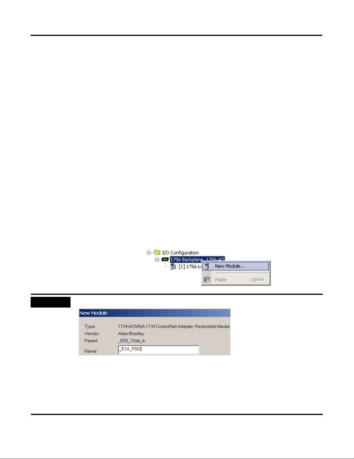
All I/O modules used by the application are inserted and configured with the
I/O configuration tool.
1. Configure all hardware I/O modules located in the chassis.
For remote I/O modules (Networks), the adapters and required I/O
modules must be configured.
The I/O module Name must correspond to the Data Retrieval Tool tag designation (import file).
This is necessary for later export of I/O Module data and backup import to the Data Retrieval Tool
data base.
The backup import is used to store the proper hardware addresses, in the Data Retrieval Tool data
base.
For Tag names and Alias designations using Asset Code (AC), refer to
N_050817_HDRS_RSLogix_Concept.pdf.
9 Publication RA-UM002B-EN-P - November 2010
Page 10
10 Developing an RSLogix 5000 Application
Import Tags with the Data Retrieval Tool CSV Files
When using the AC for tag designations, you can export a.csv file, from the
Data Retrieval Tool and import the data to RSLogix 5000. This import
automatically creates the tags and its members, for all devices specified in Data
Retrieval Tool. The .csv files are created by the Data Retrieval Tool export
function and imported into RSLogix 5000.
The Data Retrieval Tool export procedure is described in document:
HDRS-DataRetrievalTool_100.pdf
The RSLogix 5000 import procedure requires Microsoft ACCESS program:
MMCL_HDRS_DataTool_V132.mdb
The import procedure is described in document:
MMCL_HDRS-DataRetrievalTool_V130.pdf
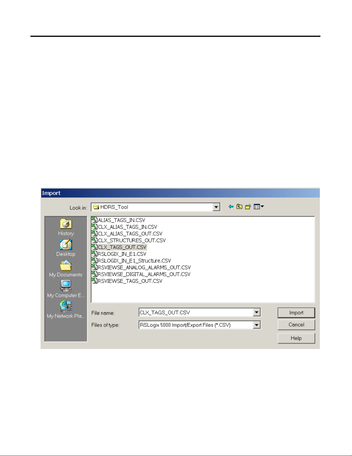
1. Under Tools, select Import.
2. Browse to the CLX_TAGS_OUT.CSV file and click Import.
Publication RA-UM002B-EN-P - November 2010
3. Complete this process for the CLX_STRUCTURES_OUT.CSV file.
Refer to the Workflow Data Retrieval Tool on page 60 for more information.
Page 11
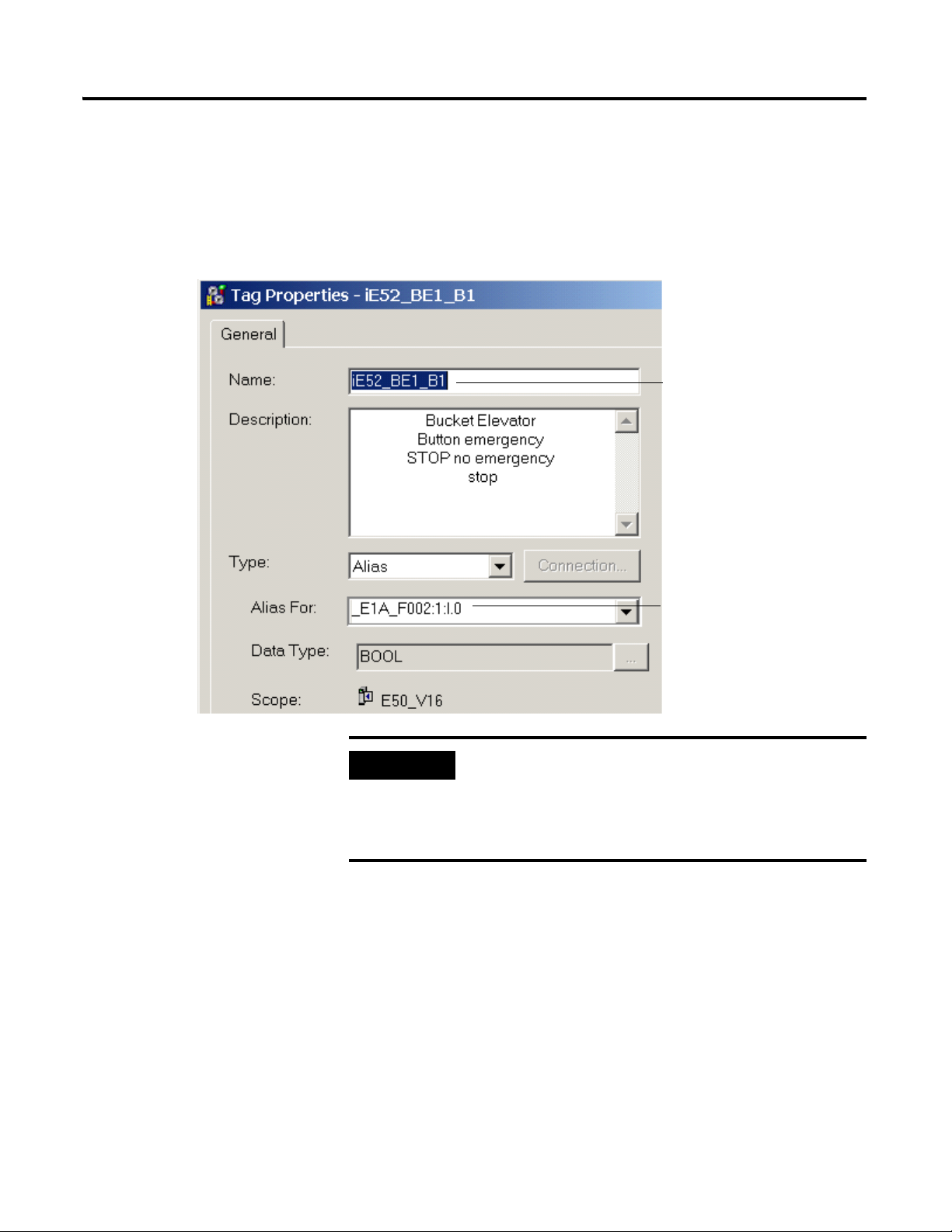
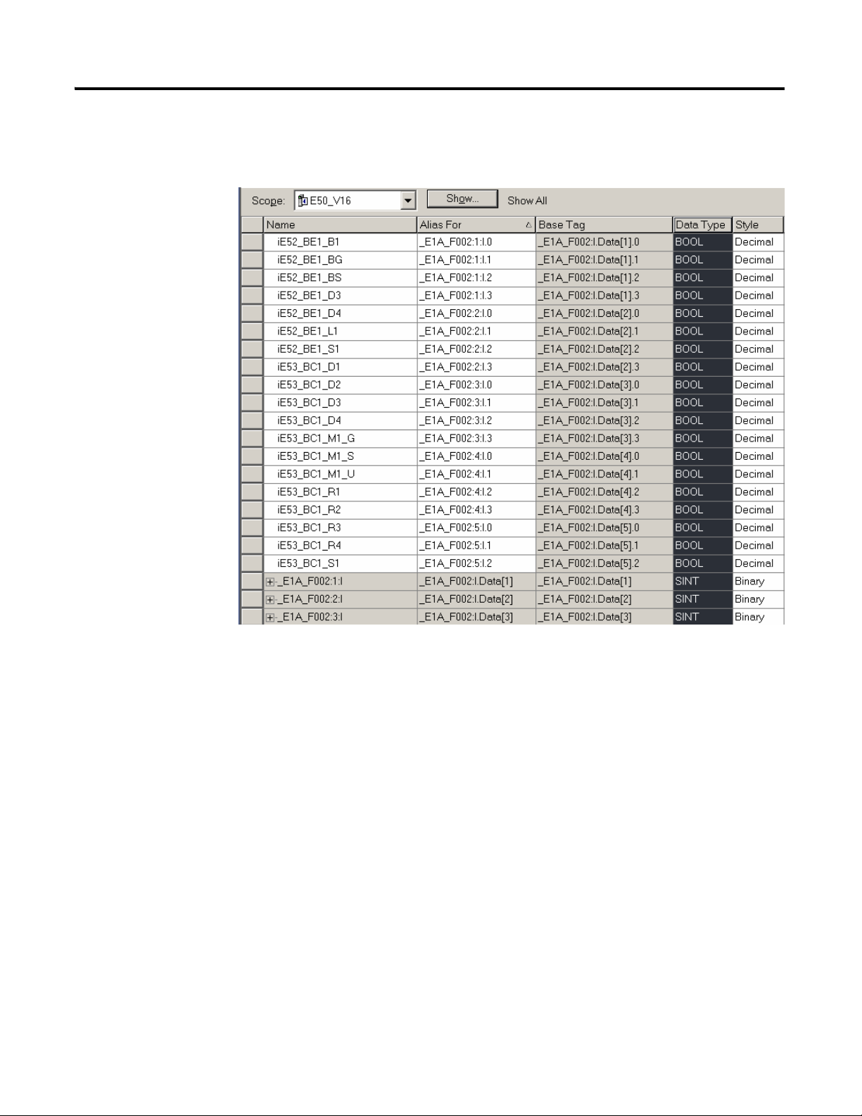
Developing an RSLogix 5000 Application 11
Tag Name imported from the Data
Retrieval Tool CSV file
I/O Address, where:
_E1A_F002 = Adapter Name
1:I.0 = Slot 1:Input Module.Bit 0
IMPORTANT
Alias I/O Descriptor
The Alias I/O descriptor specifies the exact hardware terminals and the
particular I/O module. It is therefore, necessary to know how the I/O
modules are installed and wired.
Example of Tag Properties
Do not assign the same Alias twice. We recommended that
you check for duplicate addresses prior to using the
application. Select Controller Tags and sort Alias by
ascending order, then check the list for possible
duplications.
Publication RA-UM002B-EN-P - November 2010
Page 12
12 Developing an RSLogix 5000 Application
The following is an example I/O Configuration with Controller Tags and Alias
I/O addresses:
Publication RA-UM002B-EN-P - November 2010
Page 13
Developing an RSLogix 5000 Application 13
User Programs are called in the Periodic Task. This is to improve overall
system performance. To allow proper interaction between MMCL Add-On
instruction standard functions, when multiple period tasks are used, the
Period and Priority configuration for all tasks should be the same. If different
Period and Priority is configured, then customized code has to be added to
synchronize module scan in different tasks.
Periodic Task with all User Programs
Call all User Programs including. System Rungs
For example, User Program for Network Status
MMCL AOI Standard Functions called by User
All MMCL User Data Types (UDT)
All I/O modules listed here
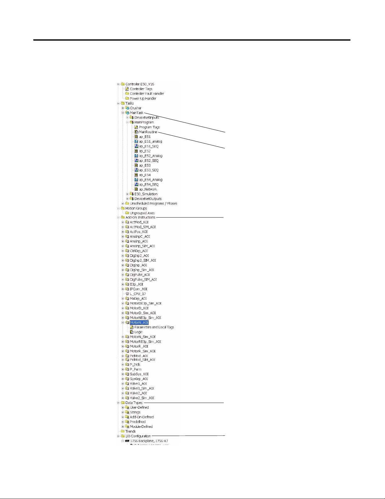
Creating User Programs
The RSLogix 5000 project originates from the MMCL_V200_20100501.acd
file. The following program and data folders are included in the project.
Publication RA-UM002B-EN-P - November 2010
Page 14

14 Developing an RSLogix 5000 Application
Program Design and Application Tips
• User Programs can be called by the Continuous or Period Tasks. When
Periodic Tasks are used, certain rules have to be followed because the
MMCL Add-On Instruction Standard Functions are originally designed
for Continuous Tasks.
• Setup the I/O module, or device parameters, immediately after a new
module is installed.
• The System Group Module, SysGrp_AOI, must be called only once in
the application. Its input, ApplyPar, signals all analog modules to read
changed parameters on-line.
• The User Program, ap_Network, is an example that shows how to get
the Network Status from an I/O Module and make it visible to the
HMI.
• The main program, MainRoutine, contains some System Rungs. These
rungs may be extended and/or adapted as required.
• Analyze the desired functions before programming. Outline the Control
and Machine Groups. Specify the calling order and start and stop
sequences of Modules within a Group.
Publication RA-UM002B-EN-P - November 2010
Page 15
Developing an RSLogix 5000 Application 15
Bus
E51_BF1_C1
SubSys/W
E51_RF2_M1
MotorN/W
E51_FN1_M1
MotorN/W
Bus
E51_000_02
MaGrp
Bus Bus
E51_MW1_V1
Valve1/F
Level
Max
Level
Max
E51_000_00
CtrlGrp
Bus
Rotary
Feeder
Filter
Fan
Bag
Filter
Last Drive
Position
Actuator
Bus
E52_000_03
MaGrp
.0
Gate PG1
E52_PG1_Z1
ActMod/F
E52_000_03.Bus
Gate 2StandbyGate 1
Select Logic
Bus
E52_000_04
MaGrp
.0
Gate PG2
E52_PG2_M1
MotorD/W
Open
Close
E52_000_04.Bus
E52_000_01
MaGrp
Bus
E52_BE1_M1
MotorN/F
E52_BE1_M2
MotorN/W
E52_000_01.Bus
Bus
E52_000_02
MaGrp
.0
E52_FA1_M1
MotorN/F
E52_3B1_WC
PidMod/W
E52_000_02.Bus
Position Feedback
Fan
Aeration
Bucket
Elevator
E52_000_00
CtrlGrp
Bus
Throttle
Gate
E52_PG0_C1_SBY
E53_BC1_M1
MotorN/F
E53_000_00
CtrlGrp
Bus
.1
.0
.1
.0 .1
E51_BC1_FC
PidMod/W
Flow
Controller
AllRun/AllStopAllRun/AllStopAllRun/AllStop
EnAutoStart
EnAuto
E51_000_03.Bus
Legend
= HMI PreSelect (Toggle)
= HMI Sel ected Indication
/W = Warning Device
/F = Failure Device
E51 Bin Extraction / Silo Feed
Group
Master
Group
Master
Group
Master
Belt
Conveyor
E52 Bin Feed E53 Recirculation
E52_PG2_C1_SEL
.0
E51_000_04
MaGrp
E51_000_01
MaGrp
E51_000_03
MaGrp
Silo 3S1Recirc Silo 3S2
E53_BC1_C1_SEL E51_3S1_C1_SEL E51_3S2_C1_SEL
.0 .1 .0 .0 .0
Silo 3S2Silo 3S1
Recircu-
lation
Local only
operation
3S1_LM
DigInp/F
3S2_LM
DigInp/F
EnAutoStart
EnAuto
EnAuto
EnAutoStart
E51_BC2_M1
MotorR/F
E51_BC1_M1
MotorN/F
E51_RF1_M1
MotorN/F
E51_RF1_S1
ActMod/F
Speed
Actuator
Rotary
Feeder
Belt
Conveyor
RdyAuto
EnAutoStart
Distribution
Gate
E51_000_01.Bus
Belt
Conveyor
Last Drive
E51_SG1_M1
MotorD/F
Slide
Gate
E51_000_04.Bus
Level
Controller
Auxiliary
Drive
Weight
Controller
RdyAutoX/Y
E52_PG2_Z1
ActMod/F
Ctrl'd Variable=SP
Position=Feed Forward FF Setpoint SP
Ctrl'd Variable=SP
E52_3B1_W1=PV
E51_BC1_F1=PV
RdyAuto
E53_000_00.Bus
P
o
s
i
t
i
o
n
C
t
r
l
'
d
V
a
r
i
a
b
l
e
E52_000_00.Bus
Y=Recirc X=Silo
Y=3S1 X=3S2
Check
Check
Check
E51_3S1_L1=PV
E51_3S1_LC
PidMod/W
I/O
I/O
I/O
I/O
I/O
I/O
I/O
I/O
I/O
I/O
I/O
I/O
I/O
I/O
I/O
I/O
I/O
I/O
I/O
I/O
I/OI/O
I/O
I/O
I/O
I/O
I/O
I/O
I/O
I/O
I/O
I/O
I/O
I/O
I/O
I/O
I/O
I/O
I/O
I/O
I/O
I/O
I/O
I/O
I/O
I/O
I/O
I/O
I/O
I/OI/O
I/O
I/O
I/O
I/O
I/O
I/O
I/O
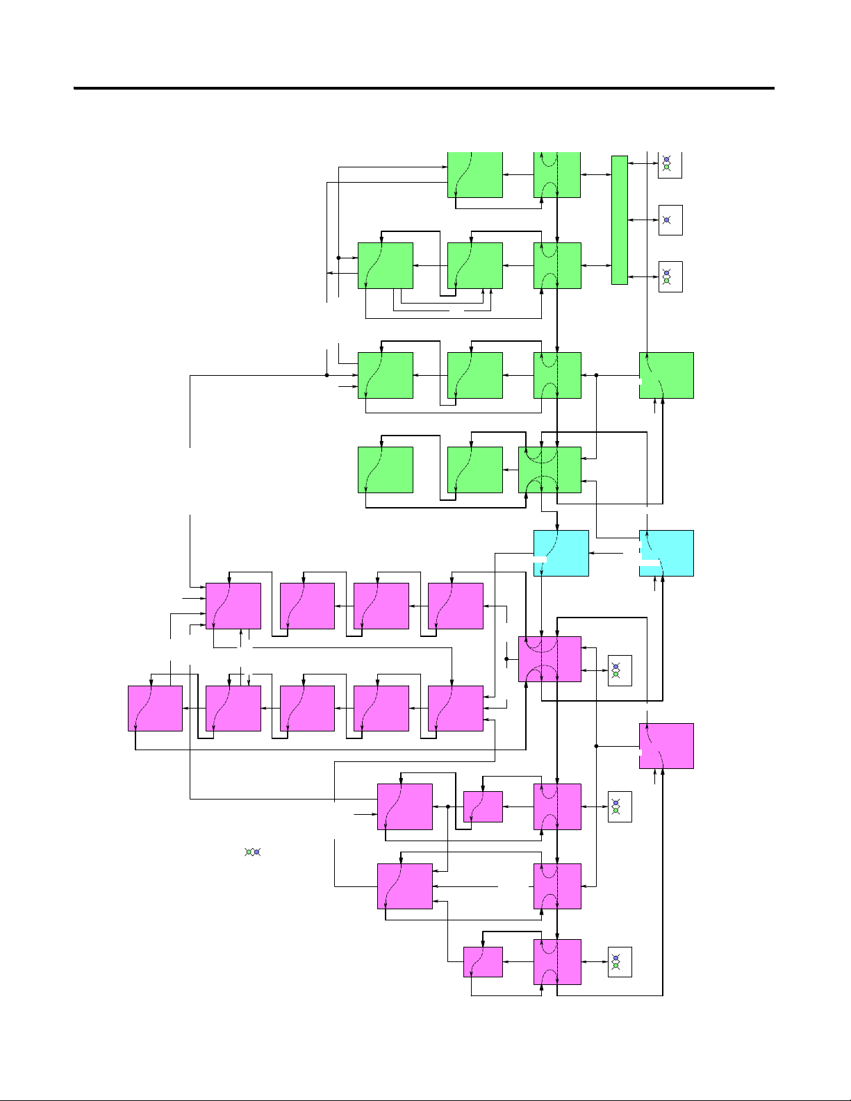
Example Application Overview
PG1_C1_SEL
Publication RA-UM002B-EN-P - November 2010
Page 16
16 Developing an RSLogix 5000 Application
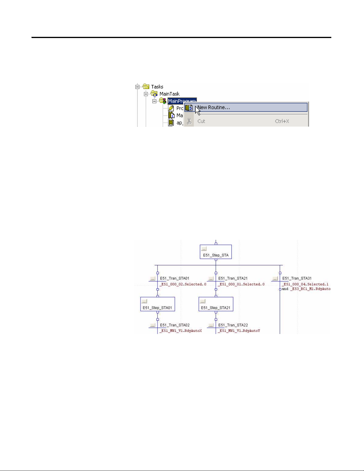
Grouping of Programs
For a clear program structure, it is recommended, to specify separate programs
for each Control Group. To start a new program, right-click the MainProgram
and select New Routine.
A Control Group may also be split functionally, using a ladder program, for
motor control I/O status and interlocking, a Sequential Function Chart
(SFC), for module start and stop sequences (including structured text) and a
Function Block Diagram (FBD), for analog process controls. The different
methods are supported by the corresponding RSLogix 5000 Editors. The
MMCL Add-On Instructions are available for Ladder, Function Block and
Structured Text.
For automatic start and stop sequences, use an SFC, especially if devices
must be stopped individually, rather than by a common shutdown command.
If, however, a common shutdown or delay time is suitable, then an SFC is not
required and a group can be stopped by the Control Group's built-in
stop-delay timer, using standard ladder interlocking only.
Publication RA-UM002B-EN-P - November 2010
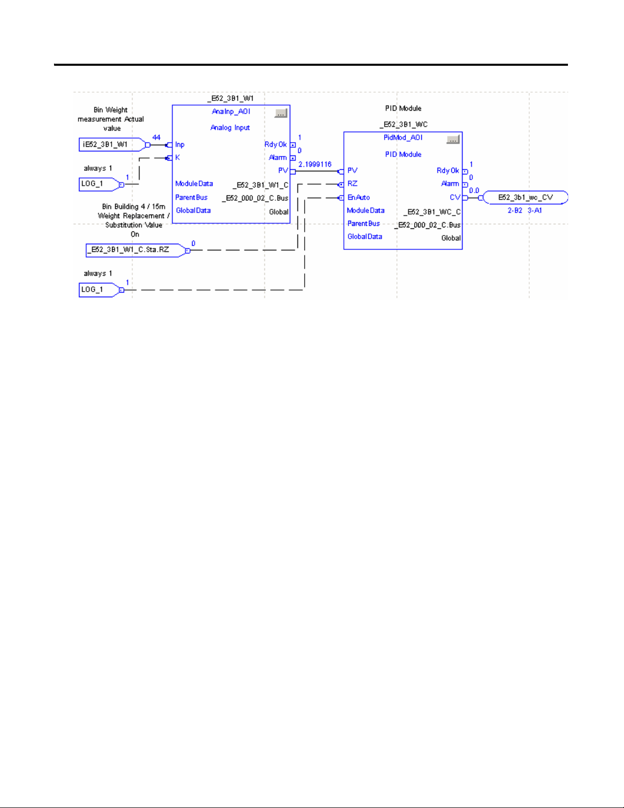
For analog signal processing, use a FBD, which is more comprehensive,
showing the signal flow better than a Ladder diagram.
Page 17
Developing an RSLogix 5000 Application 17
Publication RA-UM002B-EN-P - November 2010
Page 18

18 Developing an RSLogix 5000 Application
Notes:
Publication RA-UM002B-EN-P - November 2010
Page 19
Add-On Instruction
Function Name and Description
Backing Tag, for example _512_BC3_D1
Module Data Structure, for example
_512_BC3_D1_C
I/O connection from/to application
Bus connection to Parent Module
All Modules access the same
Global Data
Interface Definition
Rules and Recommendations
Chapter
2
The Backing Tag (instance name of the Add-On Instruction) must be unique.
The name of the ModuleData Tag is the same as the Backing Tag extended by
"_C " (for control). For example, if the Backing Tag is _512_BC3_D1, then
the ModuleData Tag is _512_BC3_D1_C.
19 Publication RA-UM002B-EN-P - November 2010
Page 20

20 Rules and Recommendations
Add-On Instruction Module Data Structure
Add-On Instruction
Backing Tag
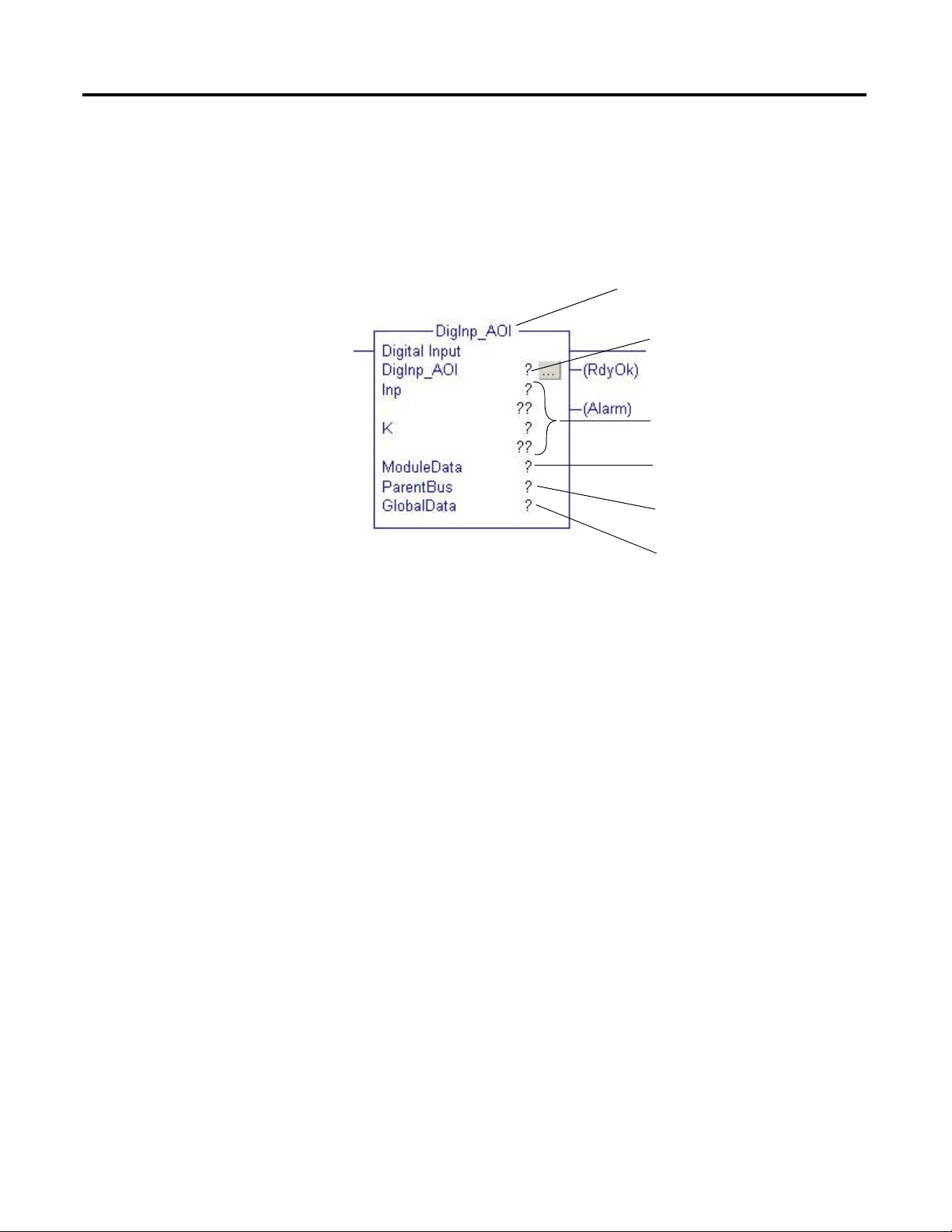
Typical Add-On Instruction Function Call
Each MMCL Add-On Instruction function has three data structures:
• All direct Inputs/Outputs are specified by the Backing Tag (instance
name of Add-On Instruction).
• The ModuleData Tag is referenced by the Add-On Instruction, this data
may be read and written by other modules/devices. It contains HMI
data (Sta, Cmd, and Val) or Parameters (Par).
• The Global Tag is used by all modules and contains common
Parameters or, for example, the interface for the Startup Warnings
(Horn/Flash) and Alarm Gong.
Publication RA-UM002B-EN-P - November 2010
Page 21

Rules and Recommendations 21
IMPORTANT
Using Parameters
It is important to set device parameters correctly in order to avoid
malfunctioning devices. After creating the tags, when importing the .csv file
from the Data Retrieval Tool, you should download the default parameter
values created by the Data Retrieval Tool, using the built in Tag
Up-/Download tool.
When you program a device, we recommend that you immediately verify the
parameter settings, according to your application.
For detailed information about parameters, see the Integrating the Mining,
Mineral, and Cement Library (MMCL) into RSLogix 5000 Reference Manual,
publication RA-RM002.
Add-On Instruction Module Parameter
The user can determine certain functions and/or the behavior of an Add-On
Instruction module by setting the parameter. The parameters are part of the
ModuleData Tag and defined as Tag members Par.xxx. Global Parameters,
that are valid for multiple Add-On Instructions, are specified by Tag members
Global.Par.xxx.
Carefully adjust and check adjust all Parameter settings
before testing your software. We recommended that you
set the parameters immediately after a new Add-On
Instruction function is applied. Make sure Module Type,
Timers [in ms], PID Gains, Filters, Alarm, Control
Thresholds, etc. are set correctly. Trouble shooting, may be
made difficult, if parameters are wrong, or not set.
Global Apply Parameter
This parameter is a special function within the System Group. If you set the
Global.ApplyPar parameter to 1, it will apply all the changes made to
parameters in the AnaInp_AOI, AnaInpC_AOI, ActMod_AOI, and
PidMod_AOI used for scaling and sample rate. If this parameter is changed,
the change does not take effect until the ApplyPar is toggled.
Publication RA-UM002B-EN-P - November 2010
Page 22

22 Rules and Recommendations
Enable Alarming in Analog Modules
To use the alarming capabilities of the AnaInp, AnaInpC and ActMod
modules, you must enable each alarm individually. This can be done by either
setting the tags <DEVICE>.EMA/.EHA/.ELA/.ENA to 1 while you are
programming the device, or by switching the tags dynamically from On to Off
through the logic program according to the application requirements.
Publication RA-UM002B-EN-P - November 2010
Page 23

Chapter
3
Control Group
The Control Group Module (CtrlGrp) provides the Human Machine Interface
(HMI) and the main control circuit, for a group of machines, or devices that
are started and stopped as an entire group. The term Group, refers to the
Asset Code (AC) definition, with the assumption that one AC Group can be
controlled by one CtrlGrp, but also may be controlled by several CtrlGrps.
The CtrlGrp accepts commands from FactoryTalk View SE. Local operator
stations, with separate start/stop pushbuttons, can also be connected. It
further accepts (for example, power failure input) or stop interlocks and it
provides outputs for the operator station, or the control room indication (for
example, mimic, alarm indication), as well as for start warning and motor
sequence control.
The CtrlGrp automatically receives/sends data from/to other modules (for
example, local enable or alarm feedback of motor modules), through its Bus
interface, in order to reduce programming workload, as well as programming
errors. The release of alarms within a group, depends on the status of the
group. If the group is active, then messages from the related modules are sent
to FactoryTalk View SE.
23 Publication RA-UM002B-EN-P - November 2010
Page 24

24 Control Group
Group Sequence Step Controller
The central part of the CtrlGrp is a seven-step controller, of which status is
available to the user. The steps 0..6 shown below, represent the actual group
status, in automatic mode. Status 0 is stopped, a normal start/stop sequence
runs the steps from 1 through 6, one after the other, and terminates at status 0,
if the group is stopped again.
Publication RA-UM002B-EN-P - November 2010
Note: An additional status "Standby" is shown for information only and has
no influence on the sequence described. The state -bit, can be used in the
application as a memory flag, to trigger an automatic start of the sequence.
Page 25

Control Group 25
Step “Ready”
Group has the ability to re-start, if step 4 “Ready” is active. Step Ready, is
active, until Group (restart) is started again. When step Ready is active, there is
a blue indication on the HMI Control- Group Popup. If the Group is restarted
with the Start button, it jumps directly to step 1 “Startup”. During this
re-starting situation, the Automatic Signal “EnAuto(X/Y)” is always true.
Only the Signal “EnAutoStart”, stays false during step 1+2 (Startup+Waiting)
and will pass over to true, if you remain at step 3 “Starting”.
The step controller not only increments steps consecutively, but may switch
(jump) to any step, in order to set a status, that complies with the new
situation. As an example, an operator Immediate Stop will, regardless of the
current status, immediately select status 0 and shutdown any control within the
group. The table below shows the additional jumps.
Start Ready Failure Normal Stop Fast Stop
Start Button
OR
Restart
Loss of last drive
AllRun=0
OR
PartRun=1
OR
Starting Pause
OR
Starting Times Out
If Parameter
FailureStopDisable=1
AND
Failure=1
Stop Button=1
OR
IntlStop.0.. 7=1
OR
FailureStopDisable=0
AND
Failure=1
ImmStop=1
IntlImmStop.0..7=1;
PowerDip
OR
OR
Publication RA-UM002B-EN-P - November 2010
Page 26

26 Control Group
* If the group has not already started a motor, status 1 and 2, will directly
pass over to status 0.
Each status change, further causes an output ResetSFC, that can be used to
initialize (reset) the Sequential Function Chart (SFC). The SFC then selects the
actual sequence (e.g. stop sequence).
Publication RA-UM002B-EN-P - November 2010
Page 27

Control Group 27
Local Operation
Interlock Release
Local operation can at any time be selected, i.e. a group may be running, while
certain machines within the same group, can be started and stopped locally.
Automatic operation uses the control sequence described above and is
transferred from the operator panel (template), by means of the group
start/stop pushbuttons and monitors for mimic displays and alarming.
Regardless of local operation, a group sequence can, at any time, be started,
when all start interlocks are satisfied.
Local operation is required for maintenance and test purposes. It is only
possible, with operator permission, to allow, or deny, local operation, for an
entire group, by means of the local button. Local operation, is always cancelled
by the CtrlGrp, if the sequence is interrupted by a Immediate Stop.
Each group can be operated with released interlocks, for commissioning, or
other special purposes. In the interlocked released mode, the inputs
IntlStart/IntlStop/IntlImmStop 0..n are inactive, however the messages are
still displayed (see CtrlGrp ModuleData Tag .Var.INR).
Power-Dip Suppression
Power-dip refers to short (less than 300 ms) main power interruptions, caused
by lighting, high voltage switching etc.
Because the main control equipment (field devices, interposing relays,
I/O-racks and PLCs as well as HMI PC's) are fed by uninterrupted power
supplies (UPS), it is possible to monitor power interruptions continuously and
prevent unnecessary shutdowns, as well as alarm messages, i.e. ignore short
power interruptions and suppress incorrect alarms caused by power outages.
Publication RA-UM002B-EN-P - November 2010
Page 28

28 Control Group
Enabling Automatic Operation
Each Control Group CtrlGrp provides two outputs, an EnAutoStart (enable
automatic start) and an EnAuto (enable automatic operation) signal, that are
used for motor control and that may be switched by Machine Group Modules
MaGrp. The bits are used in the application, to interlock the automatic
operation of modules, such as Motors/Valves etc., that use the signals as
inputs. A module will start only if both EnAutoStart AND EnAuto are ON
and it will stop if the EnAuto is OFF. A restart is only possible if the
EnAutoStart (OR the EnAuto) was set OFF for a cycle.
Note: In a chain of Devices the EnAuto Input is normally used as a process
Interlock.A following Device, has controlled his EnAuto from the previous
Module, connected to their RdyAuto.Control Group Module automatic start
/-stop timing
Publication RA-UM002B-EN-P - November 2010
Page 29

Control Group 29
EnAutoStart changes, in case of Restart conditions, to OFF, until CtrlGrp
Sequence “Starting”, then its turn ON again.
Note: Bi-directional modules as MotorR, MotorD, Valve1/2 have an
EnAutoX and an EnAutoY input, for either direction.
Signal timing EnAuto / EnAutoStart
Normal Group -start and -stop situation
Publication RA-UM002B-EN-P - November 2010
Page 30

30 Control Group
Timing situation with Restart condition (Restart Request)
Publication RA-UM002B-EN-P - November 2010
The following conditions changes the Group to “Restart Request”:
1. If any of the Alarms are on “move” - Devices such as MotorN/R/D or
Valve1,2. These Modules bring the alarm condition over the linked Bus
-chain up to the Group.
2. If the Group is in “Starting” -state and the CtrlGrp Input .PartRun is
true.
3. Or the Group is in “Running” -state and the CtrlGrp Input .AllRun
changes to false.
4. If the group is in "Starting" -state and the operator presses "Pause"
button on CtrlGrp HMI faceplate.
5. If the Group is in "Starting" -state and Starting Time Out timer times
out.
Page 31

Using the E3 Module
Chapter
4
Introduction
The E3p_AOI module is an interface block between Network (scanner) and
Motor block. Templates using the E3 module operate the same as regular
X module but with the add-on information from the E3 module:
Motor
warning status, trip status, therm., utilized and average current. The E3p_AOI
does not have a specific HMI Template. Each Motor Device with E3plus
Overload Relay will call a specific HMI Template such as
03_MotorN_E3_small or 03_MotorN_E3_largel.
There are no parameters to configure inside the E3 module structure.
31 Publication RA-UM002B-EN-P - November 2010
Page 32

32 Using the E3 Module
Principal Diagram
Publication RA-UM002B-EN-P - November 2010
Page 33

Using the E3 Module 33
IMPORTANT
E3 Installation and Wiring
Recommended Workflow
Refer to the E3 and E3 Plus Solid-State Overload Relay User Manual,
publication 193-UM002, for installation and wiring details.
System
The E3 Overload Relays provide for data exchange over the Network of
configurable Input and Output Assemblies. Inputs (Data from E3) are 8 Bytes
(4Words) and Outputs (Data to E3) are 1Byte.
Note: You can read more data out of the E3 then we have the possibility to
reach with explicit messaging. However this asynchronous messaging will
generate a high communication load at the processor.
Do not use a MSG (explicit message) operation to get data
from the E3 Device.
1. Configuration of the whole DeviceNet network related to a
DNB-Scanner Module. This is possible in Online or Offline Mode.
Remember to set the E3plus Parameter.
2. Use the DeviceNet Tag Generator to generate all Tags and Structures of
the DeviceNet Network.
3. Exchange all Data Types of E3 Data Tags which are created in the
previous step by the DeviceNet Tag Generator with common UDT,
E3_Inp and E3_Out, respectively.
4. Code programming in your application routine.
Publication RA-UM002B-EN-P - November 2010
Page 34

34 Using the E3 Module
RSNetworx for DeviceNet Software
Use the RSNetworx software to configure all E3 Overload Relays that are
connected to your network. Refer to the E3 and E3 Plus Solid-State Overload
Relay User Manual, publication 193-UM002, for more information
This document provides additional configuration information.
Publication RA-UM002B-EN-P - November 2010
Page 35

Using the E3 Module 35
E3 Operational Parameters
The following is a list of all parameters that must be set correctly in the E3. All
others that are not in this list should be left at their default value or do not take
effect with the E3p_AOI.
General Parameters
Parameter Description Required Setting
24 Trip enable See graphic on page 36
25 Warning enable See graphic on page 36
27 Single/three phase Three phases
28 FLA setting Full load amps from the motor nameplate
30 OL/PTC reset mode Manual
E3 will not reset automatically
31 OL reset level 75% (default)
User will not be able to reset E3 until therm util. is
below this value.
32 OL warning level 85% (default)
E3 will show an overload warning when therm util.
is equal or above this value.
59 Output assembly 105
60 Input assembly 100
61 Assy word 0 21 (device status)
62 Assy word 1 14 (trip status)
63 Assy word 2 4 (Therm. Util.)
64 Assy word 3 9 (Average current)
Publication RA-UM002B-EN-P - November 2010
Page 36

36 Using the E3 Module
Parameter 24 Trip enable (default)
Parameter 25 Warning enable
Publication RA-UM002B-EN-P - November 2010
Page 37

Using the E3 Module 37
DeviceNet Tag Generator
We recommend using the RSLogix 5000 tool, DeviceNet Tag Generator, to
automatically create all tags and structures in to your RSLogix 5000 project.
This tool is available on the RSLogix 5000 Optional Software CD or on the
DeviceNet Optional Tools CD.
This tool also creates additional Routines and code in your .acd project file.
The created code handles all Data exchange between the DeviceNet Scanner
Data list and your Application. This tool also creates structures and all Tags
related to each E3 with unique tag names.
The tag names take the following structure:
ScannerName_Note#_Polled_Input/Output
For example, DNB_N03_POL_I = DeviceNet Input Data from Note 3, and
DNB_N03_POL_O = DeviceNet Output Data to Note 3
The Data Type that the DeviceNet Tag Generator automatically creates is
named by the Catalog Number explanation and parameter configuration.
For example, AB_193592_EC2P_I_70847BCC
where 70847BCC is a unique code# which depends on the parameter
configuration.
Catalog Number Explanation
Publication RA-UM002B-EN-P - November 2010
Page 38

38 Using the E3 Module
Exchange Data Type
To match the tags to the E3p_AOI DataInp and DataOut, you must change
the Data Type of each E3 related Tag.
Change the tags one by one in the Controller Tag Database or use the Tag
export/import function and change the Data Type in an Excel csv file.
Note: You must know which Note Number corresponds to an E3.
Publication RA-UM002B-EN-P - November 2010
Page 39

Using the E3 Module 39
IMPORTANT
RSLogix 5000 Application
The DeviceNet Tag Generator also creates new program routines for all
DeviceNet scanner data read/write commands.
Application code example:
Always program the E3p_AOI after a Motor block. The
ParentBus is always linked to the Motor local Bus, for
example MotorName_C.Bus.
Publication RA-UM002B-EN-P - November 2010
Page 40

40 Using the E3 Module
Notes:
Publication RA-UM002B-EN-P - November 2010
Page 41

Chapter
Remote CPU
5
Inter-process Communication
The IPCom module is used for inter-process communication between two
programmable automation controllers.
With this module, the communication to a remote controller is set up and
supervising.
The main function of IPCom is to distribute the bus-data. At the same time, it
also transfers various numbers of user data, which can be allocated optionally
and, for example, used for interlocks and user data transfer to other
controllers.
The communication basis of the IPCom module uses the ControlLogix
system’s produced/consumed tags. After the programmer has created and
configured a produced/consumed tag structure, the IPCom modules plug on
to this tag, as a communication channel.
Establish Produced/Consumed Controller Tags
To establish produced/consumed controller tags, complete the following
steps.
Step1
To use the IPCom modules, you must first create and configure the link to the
remote controller.
Also, you must add the complete network, with all involved controllers, to the
I/O Configuration tree, in the RSLogix 5000 project.
Example:
41 Publication RA-UM002B-EN-P - November 2010
Page 42

42 Inter-process Communication
Step2
Create new Controller Tags. For each remote connection we have to create a
separate Tag pair. One as produced and the other as consumed type.
Example: Consumed_E2 which is linked to remote controller,
ConsumedCPU2
Produced_E2, which will produce and distribute this data.
Produced Tags have a limit of Max Consumers. It is important to specify only
the maximum number of Consumers, consuming this tag.
Publication RA-UM002B-EN-P - November 2010
Page 43

Inter-process Communication 43
Step3
Link the communication channel (produced/consumed) to IPCom module.
If more than one remote connection to the same Controller is used, an array of
IPC_Data is created and the array is extended on the required channels.
In this example, we prepared a Tag with three independent channels (to the
same Controller).
Publication RA-UM002B-EN-P - November 2010
Page 44

44 Inter-process Communication
IPCom Bus Signal Marshaling Functions Diagram
The graph below shows how the Bus is transferred through the IPCom
module and the data transmitted with Produced/Consumed function.
Publication RA-UM002B-EN-P - November 2010
Page 45

Inter-process Communication 45
Controller T ag
Master.AllRunning
Master.AllStopped
Master.Select
Slave.AllRun
Slave.AllStop
IPCom (Slave)IPCom (Ma ster)
Interlocks exchan ge
Produced
->>
Consumed
Consumed
<<-
Produced
Interlock Exchange
This graph shows how the predefined Interlock signals are linked. This
bidirectional signal exchange is used to control (select or deselect) one MaGrp
and also to bring a Group, or Device Feedback, back to the Control Group.
Publication RA-UM002B-EN-P - November 2010
Page 46

46 Inter-process Communication
IPCom.ComError CtrlGrp.MsgDisp.0
CtrlGrp
HMI-Template: Message Display
CtrlGrp.AllRun
Any .
RdyAuto
or .
Run
CtrlGrp.PartRun
Communication Error Interlock
In case of a Communication Error, all Devices on Slave IPCom will stop
immediately. The IPCom module does not have an HMI Template (popup), to
indicate this Alarm to the Operator.
To bring this information to the Operator Screen, we can use a special input at
CtrlGrp module, to show this information on the HMI CtrlGrp Popup.
Connect CtrlGrp input .MsgDisp.n to indicate our Communication Error
situation.
Furthermore, in case of failure, the CtrlGrp Input AllRun is switched off, in
order to have the possibility to restart a CtrlGrp. In this case, the CtrlGrp
changes into Ready-status.
FactoryTalk View SE Alarm List
The IPCom.Sta.CTA Tag must be added in the HMI Tag Database. This HMI
Tag is to configure as an Alarm Tag. (Sta.CTA is equal to module Output
ComError)
Publication RA-UM002B-EN-P - November 2010
Page 47

Application Examples
3
2
1
5
7
SEL
4
6
1..3 Belt conveyors mainstream
4 Silo mainstream
5..7 Belt conveyors selectable
Material Flowsheet
Chapter
6
Example 1 – One Group with Two Selectable Feeders
One Control Group with common mainstream conveyors and selectable
additional feed conveyors.
47 Publication RA-UM002B-EN-P - November 2010
Page 48

48 Application Examples
2
MotorN
5
MotorN
6
MotorN
7
MotorN
1
MotorN
AllRun
&
OR
&
&
otuAnE
otuAnE
3
MotorN
Module Outp ut: RdyAuto
Modu l e Input: EnAuto
Out: RdyA ut o Inp: EnAuto
M1.RdyAuto
CtrlGrp
MaGrp 1 MaGrp 2
0.tceleSerP
0.tceleSerP
SEL
otuAnE
tratSotuAnE
tratSotuAnE
tratSotuAnE
Legend:
Module Interlocking Diagram
Publication RA-UM002B-EN-P - November 2010
Page 49

Ctrlgrp.EnAutoStart M1.EnAutoStart
Ctrlgrp.EnAuto M1.EnAuto
Ctrlgrp.EnAutoStart
M1.RdyAuto M2.EnAuto
CtrlGrp_AOI
M1_AOI
ParentBus
CtrlGrp.Bus
M2_AOI
ParentBus
CtrlGrp.Bus
Ctrlgrp.EnAutoStart
M3_AOI
ParentBus
CtrlGrp.Bus
M3.EnAutoStart
M3.EnAuto
M2.EnAutoStart
M2.RdyAuto
SEL
MaGrp1.EnAutoStart
MaGrp1_AOI
MasterBus
CtrlGrp.Bus
SlaveBus
Dummy.Bus
M1.RdyAuto
MaGrp1.EnAuto
MaGrp1.PreSelect.0
M5.EnAutoStart
M5.EnAuto
M5_AOI
ParentBus
MaGrp1.Bus
*Machine Group 1*
*Belt conve yor 1*
*Belt conve yor 2*
*Belt conve yor 3*
*Belt conve yor 5*
M5.RdyAuto
M7.RdyAuto
*Control Group*
All devices are running in this Group
Ladder Program for Automatic Operation
CtrlGrp.AllRun
CtrlGrp.AllStop
M3.RdyAuto
M5.RdyAuto
M7.RdyAuto
SEL
SEL
M3.RdyAuto
Application Examples 49
Publication RA-UM002B-EN-P - November 2010
Page 50

50 Application Examples
SEL
M1.RdyAuto
MaGrp2.PreSelect.0
MaGrp2_AOI
MasterBus
CtrlGrp.Bus
SlaveBus
Dummy.Bus
M6.EnAutoStart
M6.EnAuto
M6_AOI
ParentBus
MaGrp2.Bus
MaGrp2.EnAuto
MaGrp2.EnAutoStart
MaGrp2.EnAutoStart
M6.RdyAuto
M7_AOI
ParentBus
MaGrp2.Bus
M7.EnAutoStart
M7.EnAuto
*Machine Group 2*
*Belt Conveyors 6*
*Belt Conveyors 7*
Publication RA-UM002B-EN-P - November 2010
Page 51

Application Examples 51
X
X
G1
G2
RF1
RF2
BC2
BC1
Material Flowsheet
Example 2 – Two Groups with One Common Conveyor
Two Control Groups using a common conveyor.
Publication RA-UM002B-EN-P - November 2010
Page 52

52 Application Examples
RF1.RdyAuto MaGrp1.Selected.0
CtrlGrp1.AllRun
CtrlGrp1
AOI
RF2.RdyAuto MaGrp1.Selected.1
CtrlGrp2.AllRun
CtrlGrp2
MaGrp1.PreSelect.0
*Machine Gr oup 1*
CtrlGrp1.Check
MaGrp1.PreSelect.1CtrlGrp2.Check
AOI
Ladder Program for Automatic Operation
AOI
*Belt conveyors 1*
MaGrp1.EnAuto
BC1.EnAutoStart
BC1.EnAuto
BC1
ParentBus
MaGrp1.Bus
AOI
*Rota ry Feeder 1*
RF1
ParentBus
MaGrp1.Bus
RF1.EnAutoStart
RF1.EnAutoBC1.RdyAuto CtrlGrp1.EnAuto
CtrlGrp1.EnAutoStart
*Belt conveyors 2*
BC2.EnAutoStart
BC2.EnAuto
BC2
ParentBus
MaGrp1.Bus
BC1.RdyAuto CtrlGrp2.RdyAuto
CtrlGrp2.EnAutoStart
AOI
AOI
MaGrp1
MasterBus
CtrlGrp1.Bus
SlaveBus
CtrlGrp2.Bus
MaGrp1.EnAutoStart
*Control Group1*
If Group selected then all Device are controlled in this Group
*Control Group2*
If Group selected then all Device are controlled in this Group
MaGrp 1
PreSelect.0 PreSelect.1
CtrlGrp1 CtrlGrp2
Module Interloc king Diagram
& &
RF1
MotorN
BC1
MotorN
.RdyAuto
.Check
AllRun AllRun
.Check
otuAnE
tratSotuAnE
tratSotuAnE
BC2
MotorN
RF2
MotorN
Module Output: RdyAuto
Modu le In put:
EnAuto
Out: RdyAuto Inp: EnAuto
Legend:
tratSotuAnE
Publication RA-UM002B-EN-P - November 2010
Page 53

Application Examples 53
Publication RA-UM002B-EN-P - November 2010
Page 54

54 Application Examples
Example 3 – One Group with Two Starts
A Control Group may be started in multiple steps, if the start-up sequence is
interrupted by switching the Group's PartRun input ON. In this case, the
CtrlGrp selects the Ready state and waits for a restart command from the
operator.
The diagram below shows how the output RdyAuto from Machine M2, can be
used to interrupt the EnAutoStart command, by control bit B=0 and
Group.PartRun=1. After restarting by the operator, the CtrlGrp starts again
with normal startup warnings. During the startup phase, the EnAutoStart is
cleared by the CtrlGrp and control bit B=1. Now Machine M3 and the
following devices will start in programmed order.
Publication RA-UM002B-EN-P - November 2010
Page 55

Application Examples 55
L
U
ONS
M2.EnAutoStart
Aux.EnStart
Aux.EnStart
LS.RdyOk
M1.RdyAuto M2.EnAuto
M2_AOI
ParentBus
CtrlGrp.Bus
*For Restart CtrlGrp Status have to change in Ready step*
LS.RdyOk
*Process Interlock*
CtrlGrp.PartRun
CtrlGrp.EnAutoStart
Example 4 Process Interlock
In this example, a Level switch (LS) will detect an Overfill situation, the
Conveyer (M2) will have to stop, until the Operator starts this group again
(Restart).
Publication RA-UM002B-EN-P - November 2010
Page 56

56 Application Examples
CtrlGrp
MaGrp1
MaGrp2
CtrlGrp
IPC1
Master
IPC2
Slave
.0
.0 .1
Remote CPU
Device_n
Device_n1
Device_y
Device_x
Program from CPU1
MOV
IPC1.Master.AllStop
*Transmit user data *
*Call IPCom module as master *
CtrlGrp.AllStop
IPC1
IPCom_AOI
(Par.MasterModule=1)
ParentBus
CtrlGrp.Bus
Source
Input_xy
Dest
IPC1.UserSend.Data[0
]
any.RdyAuto
IPC1.Master.Select
Ctrlgrp.Check
IPC1.Master.AllRun
any.RdyAuto
*PLC 1 master site *
CtrlGrp.AllRun
IPC1.Master.Select
IPC1.Master.Select
Example 5 Inter Process
Communication IPCom
Module Diagram:
Program Code:
Publication RA-UM002B-EN-P - November 2010
Page 57

Application Examples 57
Program from CPU2
MOV
MaGrp2
any.RdyAuto
IPC2.Slave.SelectMaGrp
IPC2
IPCom_AOI
(Par.MasterModule=0)
ParentBus
Dummy
IPC2.Slave.AllRunning
IPC2.Slave.AllStopped
ParentBus
IPC2.Bus
Source
IPC2.UserRec.Data[ 0]
Dest
Output_xy
*Transmit user data *
*Call IPCom module as slave *
Note: ParentBus is not connected
*PLC 2 server site*
*Control remote MaGrp *
MaGrp.PreSelect.1
any.RdyAuto
any.RdyAutoany.RdyAuto
Publication RA-UM002B-EN-P - November 2010
Page 58

58 Application Examples
Notes:
Publication RA-UM002B-EN-P - November 2010
Page 59

Additional Information
Appendix
A
RSLogix 5000 Workstation Options
Disable Duplicate Destructive Bit Detection checkbox.
59 Publication RA-UM002B-EN-P - November 2010
Page 60

60 Additional Information
Workflow Data Retrieval Tool
Publication RA-UM002B-EN-P - November 2010
Page 61

Page 62

Rockwell Otomasyon Ticaret A.Ş., Kar Plaza İş Merkezi E Blok Kat:6 34752 İçerenköy, İstanbul, Tel: +90 (216) 5698400
Rockwell Automation Support
Rockwell Automation provides technical information on the Web to assist you in using its products.
At http://www.rockwellautomation.com/support/
application notes, sample code and links to software service packs, and a MySupport feature that you can customize to make the
best use of these tools.
For an additional level of technical phone support for installation, configuration, and troubleshooting, we offer TechConnect
support programs. For more information, contact your local distributor or Rockwell Automation representative,
or visit http://www.rockwellautomation.com/support/
Installation Assistance
If you experience a problem within the first 24 hours of installation, review the information that is contained in this manual.
You can contact Customer Support for initial help in getting your product up and running.
United States or Canada 1.440.646.3434
Outside United States or
Canada
Use the Worldwide Locator
your local Rockwell Automation representative.
, you can find technical manuals, a knowledge base of FAQs, technical and
.
at http://www.rockwellautomation.com/support/americas/phone_en.html, or contact
New Product Satisfaction Return
Rockwell Automation tests all of its products to ensure that they are fully operational when shipped from the manufacturing facility.
However, if your product is not functioning and needs to be returned, follow these procedures.
United States Contact your distributor. You must provide a Customer Support case number (call the phone number above to obtain
Outside United States Please contact your local Rockwell Automation representative for the return procedure.
one) to your distributor to complete the return process.
Documentation Feedback
Your comments will help us serve your documentation needs better. If you have any suggestions on how to improve this document,
complete this form, publication RA-DU002
, available at http://www.rockwellautomation.com/literature/.
Publication RA-UM002B-EN-P - November 2010 16
Supersedes Publication RA-UM002A- EN-P - August 2007 Copyright © 2010 Rockwell Automa tion, Inc. All rights reserved. Printed in the U.S.A.
 Loading...