

Page 1

This manual links to Knowledgebase Article Logix 5000 Controller Fault
Codes for fault codes; download the spreadsheets now to ensure offline
access.
CompactLogix 5380 and
Compact GuardLogix 5380
Controllers
Bulletin 5069
User Manual
Original Instructions
Page 2
CompactLogix 5380 and Compact GuardLogix 5380 Controllers User Manual
Important User Information
Read this document and the documents listed in the additional resources section about installation, configuration, and
operation of this equipment before you install, configure, operate, or maintain this product. Users are required to familiarize
themselves with installation and wiring instructions in addition to requirements of all applicable codes, laws, and standards.
Activities including installation, adjustments, putting into service, use, assembly, disassembly, and maintenance are required to
be carried out by suitably trained personnel in accordance with applicable code of practice.
If this equipment is used in a manner not specified by the manufacturer, the protection provided by the equipment may be
impaired.
In no event will Rockwell Automation, Inc. be responsible or liable for indirect or consequential damages resulting from the use
or application of this equipment.
The examples and diagrams in this manual are included solely for illustrative purposes. Because of the many variables and
requirements associated with any particular installation, Rockwell Automation, Inc. cannot assume responsibility or liability for
actual use based on the examples and diagrams.
No patent liability is assumed by Rockwell Automation, Inc. with respect to use of information, circuits, equipment, or software
described in this manual.
Reproduction of the contents of this manual, in whole or in part, without written permission of Rockwell Automation, Inc., is
prohibited.
Throughout this manual, when necessary, we use notes to make you aware of safety considerations.
WARNING: Identifies information about practices or circumstances that can cause an explosion in a hazardous environment, which may
lead to personal injury or death, property damage, or economic loss.
ATTENTION: Identifies information about practices or circumstances that can lead to personal injury or death, property damage, or
economic loss. Attentions help you identify a hazard, avoid a hazard, and recognize the consequence.
IMPORTANT
Identifies information that is critical for successful application and understanding of the product.
Labels may also be on or inside the equipment to provide specific precautions.
SHOCK HAZARD: Labels may be on or inside the equipment, for example, a drive or motor, to alert people that dangerous voltage may
be present.
BURN HAZARD: Labels may be on or inside the equipment, for example, a drive or motor, to alert people that surfaces may reach
dangerous temperatures.
ARC FLASH HAZARD: Labels may be on or inside the equipment, for example, a motor control center, to alert people to potential Arc
Flash. Arc Flash will cause severe injury or death. Wear proper Personal Protective Equipment (PPE). Follow ALL Regulatory requirements
for safe work practices and for Personal Protective Equipment (PPE).
2 Rockwell Automation Publication 5069-UM001G-EN-P - August 2020
Page 3

Table of Contents
Preface . . . . . . . . . . . . . . . . . . . . . . . . . . . . . . . . . . . . . . . . . . . . . . . . . . . . . . .11
Summary of Changes . . . . . . . . . . . . . . . . . . . . . . . . . . . . . . . . . . . . . . . . . . 11
Catalog Numbers . . . . . . . . . . . . . . . . . . . . . . . . . . . . . . . . . . . . . . . . . . . . . 11
Overview . . . . . . . . . . . . . . . . . . . . . . . . . . . . . . . . . . . . . . . . . . . . . . . . . . . . . 11
Chapter 1
CompactLogix 5380 and Compact
GuardLogix 5380 Systems and
Controllers
How to Power CompactLogix
5380 Controllers
Minimum Requirements. . . . . . . . . . . . . . . . . . . . . . . . . . . . . . . . . . . . . . . 13
CompactLogix 5380 System . . . . . . . . . . . . . . . . . . . . . . . . . . . . . . . . . . . 15
5069-L310ER-NSE No Stored Energy (NSE) Controller . . . . . 16
CompactLogix 5380 Process controllers . . . . . . . . . . . . . . . . . . . . . 16
Compact GuardLogix 5380 System . . . . . . . . . . . . . . . . . . . . . . . . . . . . . 17
Design the System . . . . . . . . . . . . . . . . . . . . . . . . . . . . . . . . . . . . . . . . . . . . . 20
Controller Features. . . . . . . . . . . . . . . . . . . . . . . . . . . . . . . . . . . . . . . . . . . . 22
Features Supported by Compact GuardLogix 5380 Controllers
Via the Safety Task . . . . . . . . . . . . . . . . . . . . . . . . . . . . . . . . . . . . . . . . 25
Power the System . . . . . . . . . . . . . . . . . . . . . . . . . . . . . . . . . . . . . . . . . . . . . 26
Chapter 2
Two Types of Power. . . . . . . . . . . . . . . . . . . . . . . . . . . . . . . . . . . . . . . . . . . 27
MOD Power. . . . . . . . . . . . . . . . . . . . . . . . . . . . . . . . . . . . . . . . . . . . . . . . . . 29
MOD Power Bus . . . . . . . . . . . . . . . . . . . . . . . . . . . . . . . . . . . . . . . . . . 29
SA Power. . . . . . . . . . . . . . . . . . . . . . . . . . . . . . . . . . . . . . . . . . . . . . . . . . . . . 30
Track SA Power Bus Current Draw . . . . . . . . . . . . . . . . . . . . . . . . . 32
Use a 5069-FPD Field Potential Distributor to Create a
New SA Power Bus . . . . . . . . . . . . . . . . . . . . . . . . . . . . . . . . . . . . . . . . 34
SA Power - Additional Notes . . . . . . . . . . . . . . . . . . . . . . . . . . . . . . . 35
How to Power Compact
GuardLogix 5380 Controllers
Chapter 3
Two Types of Power. . . . . . . . . . . . . . . . . . . . . . . . . . . . . . . . . . . . . . . . . . . 37
MOD Power. . . . . . . . . . . . . . . . . . . . . . . . . . . . . . . . . . . . . . . . . . . . . . . . . . 39
MOD Power Bus . . . . . . . . . . . . . . . . . . . . . . . . . . . . . . . . . . . . . . . . . . 40
SA Power. . . . . . . . . . . . . . . . . . . . . . . . . . . . . . . . . . . . . . . . . . . . . . . . . . . . . 41
Track SA Power Bus Current Draw . . . . . . . . . . . . . . . . . . . . . . . . . 44
Use a 5069-FPD Field Potential Distributor to Create a
New SA Power Bus . . . . . . . . . . . . . . . . . . . . . . . . . . . . . . . . . . . . . . . . 45
Restrictions When You Connect SA Power to a Compact
GuardLogix 5380 System. . . . . . . . . . . . . . . . . . . . . . . . . . . . . . . . . . . 46
SA Power - Additional Notes . . . . . . . . . . . . . . . . . . . . . . . . . . . . . . . 49
Rockwell Automation Publication 5069-UM001G-EN-P - August 2020 3
Page 4

Table of Contents
Chapter 4
Safety Concept of Compact
GuardLogix 5380 Controllers
Functional Safety Capability . . . . . . . . . . . . . . . . . . . . . . . . . . . . . . . . . . . 51
Safety Network Number . . . . . . . . . . . . . . . . . . . . . . . . . . . . . . . . . . . . . . . 52
Safety Signature . . . . . . . . . . . . . . . . . . . . . . . . . . . . . . . . . . . . . . . . . . . . . . . 53
Distinguish Between Standard and Safety Components . . . . . . . . . . 53
Controller Data-flow Capabilities . . . . . . . . . . . . . . . . . . . . . . . . . . . . . . 54
Safety Terminology. . . . . . . . . . . . . . . . . . . . . . . . . . . . . . . . . . . . . . . . . . . . 55
Chapter 5
Connect to the Controller Before You Begin. . . . . . . . . . . . . . . . . . . . . . . . . . . . . . . . . . . . . . . . . . . . . . 57
Connection Options . . . . . . . . . . . . . . . . . . . . . . . . . . . . . . . . . . . . . . . . . . 58
Connect an Ethernet Cable . . . . . . . . . . . . . . . . . . . . . . . . . . . . . . . . 58
Connect a USB Cable. . . . . . . . . . . . . . . . . . . . . . . . . . . . . . . . . . . . . . 59
Set the IP Address . . . . . . . . . . . . . . . . . . . . . . . . . . . . . . . . . . . . . . . . . . . . . 59
Requirements . . . . . . . . . . . . . . . . . . . . . . . . . . . . . . . . . . . . . . . . . . . . . 60
Other Methods to Set the IP Address . . . . . . . . . . . . . . . . . . . . . . . 60
Use a Secure Digital Card to Set the Controller IP Address . . . 60
Duplicate IP Address Detection . . . . . . . . . . . . . . . . . . . . . . . . . . . . . . . . 60
Duplicate IP Address Resolution. . . . . . . . . . . . . . . . . . . . . . . . . . . . 61
DNS Addressing . . . . . . . . . . . . . . . . . . . . . . . . . . . . . . . . . . . . . . . . . . . . . . 61
Update Controller Firmware. . . . . . . . . . . . . . . . . . . . . . . . . . . . . . . . . . . 63
Firmware Upgrade Guidelines for Safety Controllers . . . . . . . . . 63
Controller Firmware and Logix Designer Application
Compatibility . . . . . . . . . . . . . . . . . . . . . . . . . . . . . . . . . . . . . . . . . . . . . 64
Determine Required Controller Firmware. . . . . . . . . . . . . . . . . . . 65
Obtain Controller Firmware . . . . . . . . . . . . . . . . . . . . . . . . . . . . . . . 65
Use ControlFLASH Software to Update Firmware. . . . . . . . . . . 66
Use AutoFlash to Update Firmware. . . . . . . . . . . . . . . . . . . . . . . . . 70
Controllers with Firmware Earlier than Revision 31. . . . . . . . . . . . . . 73
Chapter 6
Start to Use the Controller Create a Logix Designer Application Project. . . . . . . . . . . . . . . . . . . . . 75
Additional Configuration for a Compact GuardLogix Controller . 78
Assign the Safety Network Number (SNN). . . . . . . . . . . . . . . . . . 78
Copy and Paste a Safety Controller Safety Network Number
(SNN). . . . . . . . . . . . . . . . . . . . . . . . . . . . . . . . . . . . . . . . . . . . . . . . . . . . 83
Go Online with the Controller . . . . . . . . . . . . . . . . . . . . . . . . . . . . . . . . . 85
Use RSWho. . . . . . . . . . . . . . . . . . . . . . . . . . . . . . . . . . . . . . . . . . . . . . . 85
Use a Recent Communications Path . . . . . . . . . . . . . . . . . . . . . . . . 87
Additional Considerations for Going Online with a Controller . . . 88
Match Project to Controller . . . . . . . . . . . . . . . . . . . . . . . . . . . . . . . . 88
Firmware Revision Matching . . . . . . . . . . . . . . . . . . . . . . . . . . . . . . . 89
Additional Considerations for Going Online with a Compact
GuardLogix Controller . . . . . . . . . . . . . . . . . . . . . . . . . . . . . . . . . . . . . . . . 90
Safety Signature and Safety-locked and -unlocked Status . . . . . . 90
Checks for Going Online with a GuardLogix Controller. . . . . . 91
4 Rockwell Automation Publication 5069-UM001G-EN-P - August 2020
Page 5

Table of Contents
Download to the Controller . . . . . . . . . . . . . . . . . . . . . . . . . . . . . . . . . . . 92
Use Who Active. . . . . . . . . . . . . . . . . . . . . . . . . . . . . . . . . . . . . . . . . . . 92
Use the Controller Status Menu . . . . . . . . . . . . . . . . . . . . . . . . . . . . 93
Additional Considerations for Download to a
Compact GuardLogix Controller. . . . . . . . . . . . . . . . . . . . . . . . . . . . . . . 93
Upload from the Controller. . . . . . . . . . . . . . . . . . . . . . . . . . . . . . . . . . . . 95
Use Who Active. . . . . . . . . . . . . . . . . . . . . . . . . . . . . . . . . . . . . . . . . . . 95
Use the Controller Status Menu . . . . . . . . . . . . . . . . . . . . . . . . . . . . 96
Additional Considerations for Upload to a
Compact GuardLogix Controller. . . . . . . . . . . . . . . . . . . . . . . . . . . . . . . 98
Choose the Controller Operation Mode . . . . . . . . . . . . . . . . . . . . . . . . 99
Use the Mode Switch to Change the Operation Mode . . . . . . . 100
Use the Logix Designer Application to Change the
Operation Mode . . . . . . . . . . . . . . . . . . . . . . . . . . . . . . . . . . . . . . . . . 101
Change Controller Configuration . . . . . . . . . . . . . . . . . . . . . . . . . . . . . 102
Reset Button. . . . . . . . . . . . . . . . . . . . . . . . . . . . . . . . . . . . . . . . . . . . . . . . . 103
Stage 1 Reset . . . . . . . . . . . . . . . . . . . . . . . . . . . . . . . . . . . . . . . . . . . . . 104
Stage 2 Reset . . . . . . . . . . . . . . . . . . . . . . . . . . . . . . . . . . . . . . . . . . . . . 105
Chapter 7
Use the Secure Digital Card Overview . . . . . . . . . . . . . . . . . . . . . . . . . . . . . . . . . . . . . . . . . . . . . . . . . . . . 107
Considerations for Storing and Loading a Safety Project . . . . . . . . . 110
Store to the SD Card . . . . . . . . . . . . . . . . . . . . . . . . . . . . . . . . . . . . . . . . . 111
Load from the SD Card. . . . . . . . . . . . . . . . . . . . . . . . . . . . . . . . . . . . . . . 115
Controller Power-up. . . . . . . . . . . . . . . . . . . . . . . . . . . . . . . . . . . . . . 115
User-initiated Action . . . . . . . . . . . . . . . . . . . . . . . . . . . . . . . . . . . . . 116
Other Secure Digital Card Tasks . . . . . . . . . . . . . . . . . . . . . . . . . . . . . . 118
Chapter 8
EtherNet/IP Network Overview . . . . . . . . . . . . . . . . . . . . . . . . . . . . . . . . . . . . . . . . . . . . . . . . . . . . 119
EtherNet/IP Network Functionality. . . . . . . . . . . . . . . . . . . . . . . . . . . 120
Nodes on an EtherNet/IP Network. . . . . . . . . . . . . . . . . . . . . . . . . . . . 121
Devices Included in the Node Count. . . . . . . . . . . . . . . . . . . . . . . 121
Devices Excluded from the Node Count. . . . . . . . . . . . . . . . . . . . 122
EtherNet/IP Network Topologies . . . . . . . . . . . . . . . . . . . . . . . . . . . . . 124
Device Level Ring Network Topology. . . . . . . . . . . . . . . . . . . . . . 124
Linear Network Topology. . . . . . . . . . . . . . . . . . . . . . . . . . . . . . . . . 125
Star Network Topology . . . . . . . . . . . . . . . . . . . . . . . . . . . . . . . . . . . 126
Integrated Architecture Tools . . . . . . . . . . . . . . . . . . . . . . . . . . . . . 126
EtherNet/IP Network Communication Rates . . . . . . . . . . . . . . . . . . 127
Simple Network Management Protocol (SNMP) . . . . . . . . . . . . . . . 129
Use a CIP Generic MSG to Enable SNMP on the Controller. 129
Use a CIP Generic MSG to Disable SNMP on the Controller 131
Socket Interface . . . . . . . . . . . . . . . . . . . . . . . . . . . . . . . . . . . . . . . . . . . . . . 133
Rockwell Automation Publication 5069-UM001G-EN-P - August 2020 5
Page 6

Table of Contents
Chapter 9
Use EtherNet/IP Modes Overview . . . . . . . . . . . . . . . . . . . . . . . . . . . . . . . . . . . . . . . . . . . . . . . . . . . . 135
Available Network Levels . . . . . . . . . . . . . . . . . . . . . . . . . . . . . . . . . . . . . 136
Enterprise-level Network. . . . . . . . . . . . . . . . . . . . . . . . . . . . . . . . . . 136
Device-level Network . . . . . . . . . . . . . . . . . . . . . . . . . . . . . . . . . . . . . 137
EtherNet/IP Modes . . . . . . . . . . . . . . . . . . . . . . . . . . . . . . . . . . . . . . . . . . 137
Dual-IP Mode. . . . . . . . . . . . . . . . . . . . . . . . . . . . . . . . . . . . . . . . . . . . 137
Linear/DLR Mode . . . . . . . . . . . . . . . . . . . . . . . . . . . . . . . . . . . . . . . 141
Overlapping IP Address Ranges . . . . . . . . . . . . . . . . . . . . . . . . . . . . . . . 143
Configure the EtherNet/IP Modes . . . . . . . . . . . . . . . . . . . . . . . . . . . . 144
Configure Dual-IP Mode in the Logix Designer Application . 144
Configure Dual-IP Mode in RSLinx Classic Software. . . . . . . . 146
Configure Linear/DLR Mode in the
Logix Designer Application . . . . . . . . . . . . . . . . . . . . . . . . . . . . . . . 148
Configure Linear/DLR Mode in RSLinx Classic Software . . . 150
Change the EtherNet/IP Mode . . . . . . . . . . . . . . . . . . . . . . . . . . . . . . . 152
Change the EtherNet/IP Mode in the
Logix Designer Application . . . . . . . . . . . . . . . . . . . . . . . . . . . . . . . 153
Change the EtherNet/IP Mode in RSLinx Classic Software . . 155
DNS Requests. . . . . . . . . . . . . . . . . . . . . . . . . . . . . . . . . . . . . . . . . . . . 158
DNS Request Routing . . . . . . . . . . . . . . . . . . . . . . . . . . . . . . . . . . . . 158
SMTP Server. . . . . . . . . . . . . . . . . . . . . . . . . . . . . . . . . . . . . . . . . . . . . 159
Use Socket Object . . . . . . . . . . . . . . . . . . . . . . . . . . . . . . . . . . . . . . . . 159
Send Message Instructions . . . . . . . . . . . . . . . . . . . . . . . . . . . . . . . . 159
Software Display Differences for EtherNet/IP Modes . . . . . . . 160
Chapter 10
Manage Controller
Communication
Connection Overview . . . . . . . . . . . . . . . . . . . . . . . . . . . . . . . . . . . . . . . . 163
Controller Communication Interaction with Control Data. . . . . . 164
Produce and Consume (Interlock) Data. . . . . . . . . . . . . . . . . . . . . . . . 165
Requested Packet Interval (RPI) of Multicast Tags . . . . . . . . . . 166
Send and Receive Messages. . . . . . . . . . . . . . . . . . . . . . . . . . . . . . . . . . . . 167
Determine Whether to Cache Message Connections . . . . . . . . 168
Chapter 11
Standard I/O Modules Local I/O Modules . . . . . . . . . . . . . . . . . . . . . . . . . . . . . . . . . . . . . . . . . . . 169
Add Local I/O Modules to a Project . . . . . . . . . . . . . . . . . . . . . . . 171
Electronic Keying. . . . . . . . . . . . . . . . . . . . . . . . . . . . . . . . . . . . . . . . . 176
Remote I/O Modules. . . . . . . . . . . . . . . . . . . . . . . . . . . . . . . . . . . . . . . . . 177
Add Remote I/O Modules to a Project . . . . . . . . . . . . . . . . . . . . . 179
Add to the I/O Configuration While Online . . . . . . . . . . . . . . . . . . . 187
Modules and Devices That Can Be Added While Online . . . . 187
Determine When Data Is Updated . . . . . . . . . . . . . . . . . . . . . . . . . . . . 188
Input Data Update Flowchart . . . . . . . . . . . . . . . . . . . . . . . . . . . . . 188
Output Data Update Flowchart . . . . . . . . . . . . . . . . . . . . . . . . . . . 189
6 Rockwell Automation Publication 5069-UM001G-EN-P - August 2020
Page 7

Table of Contents
Chapter 12
Safety I/O Devices Add Safety I/O Devices. . . . . . . . . . . . . . . . . . . . . . . . . . . . . . . . . . . . . . . 191
Configure Safety I/O Devices . . . . . . . . . . . . . . . . . . . . . . . . . . . . . . . . . 192
Using Network Address Translation (NAT) with
CIP Safety Devices . . . . . . . . . . . . . . . . . . . . . . . . . . . . . . . . . . . . . . . . . . . 194
Set the SNN of a Safety I/O Device . . . . . . . . . . . . . . . . . . . . . . . . . . . . 196
Change a Safety I/O Device SNN. . . . . . . . . . . . . . . . . . . . . . . . . . 196
Copy and Paste a Safety I/O Device Safety Network Number
(SNN). . . . . . . . . . . . . . . . . . . . . . . . . . . . . . . . . . . . . . . . . . . . . . . . . . . 198
Connection Reaction Time Limit . . . . . . . . . . . . . . . . . . . . . . . . . . . . . 200
Safety I/O Device Signature. . . . . . . . . . . . . . . . . . . . . . . . . . . . . . . . . . . 201
Configuration Via the Logix Designer Application . . . . . . . . . . 201
Reset Safety I/O Device to Out-of-box Condition. . . . . . . . . . . 202
I/O Device Address Format . . . . . . . . . . . . . . . . . . . . . . . . . . . . . . . . . . . 203
Replace a Safety I/O Device . . . . . . . . . . . . . . . . . . . . . . . . . . . . . . . . . . . 204
Configuration Ownership. . . . . . . . . . . . . . . . . . . . . . . . . . . . . . . . . 204
Replacement with ‘Configure Only When No Safety
Signature Exists’ Enabled. . . . . . . . . . . . . . . . . . . . . . . . . . . . . . . . . . 206
Replacement with ‘Configure Always’ Enabled. . . . . . . . . . . . . . 211
Chapter 13
Develop Standard Applications Elements of a Control Application. . . . . . . . . . . . . . . . . . . . . . . . . . . . . 213
Tasks. . . . . . . . . . . . . . . . . . . . . . . . . . . . . . . . . . . . . . . . . . . . . . . . . . . . . . . . 215
Event Task with Compact 5000 I/O Modules . . . . . . . . . . . . . . 217
Task Priority . . . . . . . . . . . . . . . . . . . . . . . . . . . . . . . . . . . . . . . . . . . . . 219
Programs . . . . . . . . . . . . . . . . . . . . . . . . . . . . . . . . . . . . . . . . . . . . . . . . . . . . 220
Scheduled and Unscheduled Programs . . . . . . . . . . . . . . . . . . . . . 221
Routines. . . . . . . . . . . . . . . . . . . . . . . . . . . . . . . . . . . . . . . . . . . . . . . . . . . . . 222
Parameters and Local Tags . . . . . . . . . . . . . . . . . . . . . . . . . . . . . . . . . . . . 223
Program Parameters . . . . . . . . . . . . . . . . . . . . . . . . . . . . . . . . . . . . . . 224
Programming Languages . . . . . . . . . . . . . . . . . . . . . . . . . . . . . . . . . . . . . . 224
Add-On Instructions . . . . . . . . . . . . . . . . . . . . . . . . . . . . . . . . . . . . . . . . . 225
Extended Properties . . . . . . . . . . . . . . . . . . . . . . . . . . . . . . . . . . . . . . . . . . 226
Access the Module Object from an Add-On Instruction . . . . . . . . . 227
Monitor Controller Status . . . . . . . . . . . . . . . . . . . . . . . . . . . . . . . . . . . . 228
Monitor I/O Connections . . . . . . . . . . . . . . . . . . . . . . . . . . . . . . . . . . . . 229
Determine If I/O Communication Has Timed Out . . . . . . . . . 229
Determine If I/O Communication to a Specific I/O Module
Has Timed Out . . . . . . . . . . . . . . . . . . . . . . . . . . . . . . . . . . . . . . . . . . 230
Automatic Handling of I/O Module Connection Faults . . . . . 230
Sample Controller Projects . . . . . . . . . . . . . . . . . . . . . . . . . . . . . . . . 231
Rockwell Automation Publication 5069-UM001G-EN-P - August 2020 7
Page 8

Table of Contents
Chapter 14
Develop Safety Applications Overview . . . . . . . . . . . . . . . . . . . . . . . . . . . . . . . . . . . . . . . . . . . . . . . . . . . . 233
Safety Task . . . . . . . . . . . . . . . . . . . . . . . . . . . . . . . . . . . . . . . . . . . . . . . . . . 234
Safety Task Period . . . . . . . . . . . . . . . . . . . . . . . . . . . . . . . . . . . . . . . . 235
Safety Task Execution. . . . . . . . . . . . . . . . . . . . . . . . . . . . . . . . . . . . . 236
Safety Programs . . . . . . . . . . . . . . . . . . . . . . . . . . . . . . . . . . . . . . . . . . . . . . 236
Safety Routines . . . . . . . . . . . . . . . . . . . . . . . . . . . . . . . . . . . . . . . . . . . . . . 236
Safety Add-On Instructions . . . . . . . . . . . . . . . . . . . . . . . . . . . . . . . . . . . 237
Safety Tags . . . . . . . . . . . . . . . . . . . . . . . . . . . . . . . . . . . . . . . . . . . . . . . . . . 237
Valid Data Types . . . . . . . . . . . . . . . . . . . . . . . . . . . . . . . . . . . . . . . . . 238
Scope . . . . . . . . . . . . . . . . . . . . . . . . . . . . . . . . . . . . . . . . . . . . . . . . . . . . 238
Program Parameters . . . . . . . . . . . . . . . . . . . . . . . . . . . . . . . . . . . . . . . . . . 239
Produced/Consumed Safety Tags. . . . . . . . . . . . . . . . . . . . . . . . . . . . . . 239
Configure the SNN for a Peer Safety Controller Connection. 240
Produce a Safety Tag. . . . . . . . . . . . . . . . . . . . . . . . . . . . . . . . . . . . . . 244
Consume Safety Tag Data. . . . . . . . . . . . . . . . . . . . . . . . . . . . . . . . . 245
Safety Tag Mapping . . . . . . . . . . . . . . . . . . . . . . . . . . . . . . . . . . . . . . . . . . 248
Restrictions . . . . . . . . . . . . . . . . . . . . . . . . . . . . . . . . . . . . . . . . . . . . . . 248
Create Tag Mapping Pairs. . . . . . . . . . . . . . . . . . . . . . . . . . . . . . . . . 249
Monitor Tag Mapping Status. . . . . . . . . . . . . . . . . . . . . . . . . . . . . . 250
Safety Application Protection . . . . . . . . . . . . . . . . . . . . . . . . . . . . . . . . . 251
Safety-lock the Compact GuardLogix 5380 Controller . . . . . . 251
Set Passwords for Safety-locking and Unlocking. . . . . . . . . . . . . 253
Generate the Safety Signature. . . . . . . . . . . . . . . . . . . . . . . . . . . . . . 254
Programming Restrictions . . . . . . . . . . . . . . . . . . . . . . . . . . . . . . . . . . . . 257
Monitor Safety Status . . . . . . . . . . . . . . . . . . . . . . . . . . . . . . . . . . . . . . . . 258
View Status Via the Online Bar . . . . . . . . . . . . . . . . . . . . . . . . . . . . 258
View Status Via the Safety Tab . . . . . . . . . . . . . . . . . . . . . . . . . . . . 260
Monitor Safety Connections . . . . . . . . . . . . . . . . . . . . . . . . . . . . . . 261
Utilize Status. . . . . . . . . . . . . . . . . . . . . . . . . . . . . . . . . . . . . . . . . . . . . 262
Safety Faults . . . . . . . . . . . . . . . . . . . . . . . . . . . . . . . . . . . . . . . . . . . . . . . . . 264
Nonrecoverable Controller Faults. . . . . . . . . . . . . . . . . . . . . . . . . . 264
Nonrecoverable Safety Faults in the Safety Application . . . . . . 264
Recoverable Faults in the Safety Application . . . . . . . . . . . . . . . . 265
View Faults . . . . . . . . . . . . . . . . . . . . . . . . . . . . . . . . . . . . . . . . . . . . . . 265
Fault Codes . . . . . . . . . . . . . . . . . . . . . . . . . . . . . . . . . . . . . . . . . . . . . . 266
Develop a Fault Routine for Safety Applications . . . . . . . . . . . . . . . . 267
Use GSV/SSV Instructions in a Safety Application. . . . . . . . . . . . . . 268
Chapter 15
Develop Motion Applications Overview . . . . . . . . . . . . . . . . . . . . . . . . . . . . . . . . . . . . . . . . . . . . . . . . . . . . 269
Motion Overview . . . . . . . . . . . . . . . . . . . . . . . . . . . . . . . . . . . . . . . . . . . . 270
Program Motion Control . . . . . . . . . . . . . . . . . . . . . . . . . . . . . . . . . . . . . 271
Obtain Axis Information . . . . . . . . . . . . . . . . . . . . . . . . . . . . . . . . . . . . . 273
8 Rockwell Automation Publication 5069-UM001G-EN-P - August 2020
Page 9

Table of Contents
Chapter 16
Troubleshoot the Controller Automatic Diagnostics . . . . . . . . . . . . . . . . . . . . . . . . . . . . . . . . . . . . . . . 275
Considerations for Communication Loss Diagnostics . . . . . . . . . . . 276
Controller Diagnostics with Logix Designer . . . . . . . . . . . . . . . . . . . . 276
Warning Symbol in the I/O Configuration Tree . . . . . . . . . . . . 277
Categories on I/O Module Properties Dialog . . . . . . . . . . . . . . . 278
Notification in the Tag Monitor . . . . . . . . . . . . . . . . . . . . . . . . . . . 282
Fault Information in the Controller Properties Dialog Box. . . 282
Port Diagnostics. . . . . . . . . . . . . . . . . . . . . . . . . . . . . . . . . . . . . . . . . . 284
Advanced Time Sync . . . . . . . . . . . . . . . . . . . . . . . . . . . . . . . . . . . . . 286
Controller Diagnostics with Linx-based Software . . . . . . . . . . . . . . . 289
Controller Web Pages . . . . . . . . . . . . . . . . . . . . . . . . . . . . . . . . . . . . . . . . 290
Home Web Page . . . . . . . . . . . . . . . . . . . . . . . . . . . . . . . . . . . . . . . . . 291
Tasks Web Page . . . . . . . . . . . . . . . . . . . . . . . . . . . . . . . . . . . . . . . . . . 292
Diagnostics Web Pages. . . . . . . . . . . . . . . . . . . . . . . . . . . . . . . . . . . . 293
Ethernet Port Web Pages. . . . . . . . . . . . . . . . . . . . . . . . . . . . . . . . . . 294
Advanced Diagnostics Web Pages. . . . . . . . . . . . . . . . . . . . . . . . . . 295
Browse Chassis Web Page . . . . . . . . . . . . . . . . . . . . . . . . . . . . . . . . . 297
Other Potential Issues to Troubleshoot . . . . . . . . . . . . . . . . . . . . . . . . 298
Continuous Task Sends Output Data at High Rate. . . . . . . . . . 298
Immediate Output Instructions Issued at High Rate. . . . . . . . . 298
Integrated Motion On an EtherNet/IP Network Traffic
Priority Status. . . . . . . . . . . . . . . . . . . . . . . . . . . . . . . . . . . . . . . . . . . . 298
Appendix A
Status Indicators Status Display and Indicators. . . . . . . . . . . . . . . . . . . . . . . . . . . . . . . . . . 300
General Status Messages . . . . . . . . . . . . . . . . . . . . . . . . . . . . . . . . . . . . . . 301
Compact GuardLogix Status Messages . . . . . . . . . . . . . . . . . . . . . . . . . 303
Fault Messages . . . . . . . . . . . . . . . . . . . . . . . . . . . . . . . . . . . . . . . . . . . . . . . 303
Major Fault Messages . . . . . . . . . . . . . . . . . . . . . . . . . . . . . . . . . . . . . . . . . 305
I/O Fault Codes . . . . . . . . . . . . . . . . . . . . . . . . . . . . . . . . . . . . . . . . . . . . . 305
Controller Status Indicators. . . . . . . . . . . . . . . . . . . . . . . . . . . . . . . . . . . 306
RUN Indicator. . . . . . . . . . . . . . . . . . . . . . . . . . . . . . . . . . . . . . . . . . . 306
FORCE Indicator . . . . . . . . . . . . . . . . . . . . . . . . . . . . . . . . . . . . . . . . 306
SD Indicator . . . . . . . . . . . . . . . . . . . . . . . . . . . . . . . . . . . . . . . . . . . . . 307
OK Indicator . . . . . . . . . . . . . . . . . . . . . . . . . . . . . . . . . . . . . . . . . . . . 307
EtherNet/IP Status Indicators. . . . . . . . . . . . . . . . . . . . . . . . . . . . . . . . . 308
NET A1 and NET A2 Indicators . . . . . . . . . . . . . . . . . . . . . . . . . . 308
LINK A1 and LINK A2 Indicators . . . . . . . . . . . . . . . . . . . . . . . . 308
Power Status Indicators. . . . . . . . . . . . . . . . . . . . . . . . . . . . . . . . . . . . . . . 309
MOD Power Indicator. . . . . . . . . . . . . . . . . . . . . . . . . . . . . . . . . . . . 309
SA Power Indicator. . . . . . . . . . . . . . . . . . . . . . . . . . . . . . . . . . . . . . . 309
Thermal Monitoring and Thermal Fault Behavior . . . . . . . . . . . . . . 310
Rockwell Automation Publication 5069-UM001G-EN-P - August 2020 9
Page 10

Table of Contents
Appendix B
Security Options Disable an Ethernet Port. . . . . . . . . . . . . . . . . . . . . . . . . . . . . . . . . . . . . . 311
Disable the Ethernet Port on the Port Configuration Tab. . . . 312
Disable the Ethernet Port with a MSG Instruction . . . . . . . . . . 313
Disable the 4-character Status Display. . . . . . . . . . . . . . . . . . . . . . . . . . 315
Disable All Categories of Messages . . . . . . . . . . . . . . . . . . . . . . . . . 316
Disable Individual Categories of Messages . . . . . . . . . . . . . . . . . . 318
Disable the Controller Web Pages . . . . . . . . . . . . . . . . . . . . . . . . . . . . . 320
Studio 5000 Logix Designer Application Version 33.00.00
and Later . . . . . . . . . . . . . . . . . . . . . . . . . . . . . . . . . . . . . . . . . . . . . . . . 320
Studio 5000 Logix Designer Application Version 32.00.00
or Earlier. . . . . . . . . . . . . . . . . . . . . . . . . . . . . . . . . . . . . . . . . . . . . . . . . 320
Controller Web Page Default Settings. . . . . . . . . . . . . . . . . . . . . . 321
Use a CIP Generic MSG to Disable the Controller Web Pages 322
Use a CIP Generic MSG to Enable the Controller Web Pages 324
Appendix C
Change Controller Type Change from a Standard to a Safety Controller . . . . . . . . . . . . . . . . . 327
Change from a Safety to a Standard Controller . . . . . . . . . . . . . . . . . 328
Change Safety Controller Types . . . . . . . . . . . . . . . . . . . . . . . . . . . . . . . 329
Index . . . . . . . . . . . . . . . . . . . . . . . . . . . . . . . . . . . . . . . . . . . . . . . . . . . . . . 331
10 Rockwell Automation Publication 5069-UM001G-EN-P - August 2020
Page 11
Preface
Summary of Changes
Catalog Numbers
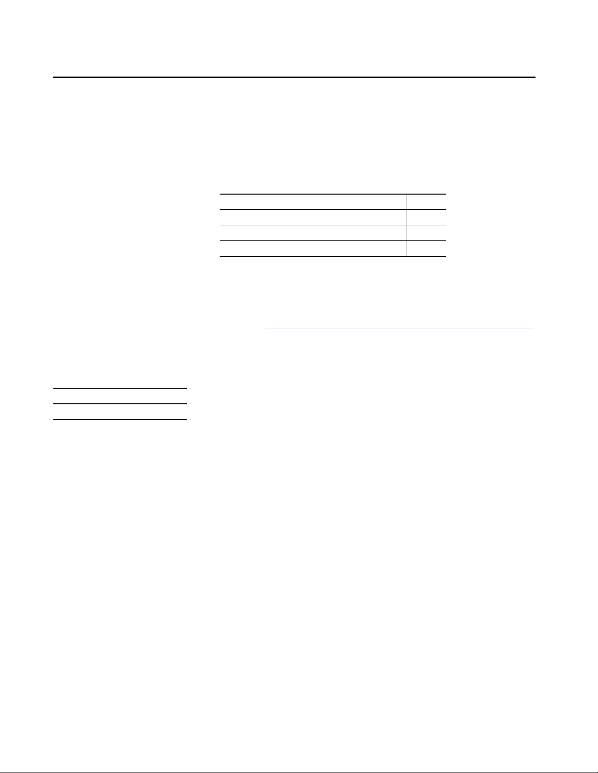
This manual contains new and updated information as indicated in the
following table.
Top ic Pag e
Added CompactLogix™ 5380 Process controllers. Throughout
Updated safety signature definition. 53
Added Simple Network Management Protocol (SNMP). 129
Added Automatic Diagnostics. 275
Added Considerations for Communication Loss Diagnostics. 276
Updated the Disable Controller Web Pages procedure. 320
This publication is applicable to these controllers:
CompactLogix 5380 Standard Catalog Numbers: 5069-L306ER, 5069-L306ERM, 5069-L310ER, 5069-L310ERM,
5069-L310ER-NSE, 5069-L320ER, 5069-L320ERM, 5069-L320ERMK,
5069-L330ER, 5069-L330ERM, 5069-L330ERMK, 5069-L340ER, 5069-L340ERM,
5069-L350ERM, 5069-L350ERMK, 5069-L380ERM, 5069-L3100ERM
CompactLogix 5380 Process Catalog Numbers: 5069-L320ERP, 5069-L340ERP
Compact GuardLogix® 5380 SIL 2 Catalog Numbers: 5069-L306ERS2, 5069-L306ERMS2, 5069-L310ERS2, 5069-L310ERMS2,
5069-L320ERS2, 5069-L320ERS2K, 5069-L320ERMS2, 5069-L320ERMS2K,
5069-L330ERS2, 5069-L330ERS2K, 5069-L330ERMS2, 5069-L330ERMS2K,
5069-L340ERS2, 5069-L340ERMS2, 5069-L350ERS2, 5069-L350ERS2K,
5069-L350ERMS2, 5069-L350ERMS2K, 5069-L380ERS2, 5069-L380ERMS2,
5069-L3100ERS2, 5069-L3100ERMS2
Compact GuardLogix 5380 SIL 3 Catalog Numbers: 5069-L306ERMS3, 5069-L310ERMS3, 5069-L320ERMS3, 5069-L320ERMS3K,
5069-L330ERMS3, 5069-L330ERMS3K, 5069-L340ERMS3, 5069-L350ERMS3,
5069-L350ERMS3K, 5069-L380ERMS3, 5069-L3100ERMS3
Overview
This manual provides information on how to design a system, operate a
CompactLogix or Compact GuardLogix-based controllers system, and develop
applications.
You must be trained and experienced in the creation, operation, and
maintenance of safety systems.
For information on Safety Integrity Level (SIL) and Performance Level (PL)
requirements and safety application requirements, see the GuardLogix 5580
and Compact GuardLogix 5380 Controller Systems Safety Reference Manual,
publication 1756-RM012.
Rockwell Automation Publication 5069-UM001G-EN-P - August 2020 11
Page 12

Preface
Notes:
12 Rockwell Automation Publication 5069-UM001G-EN-P - August 2020
Page 13
Chapter 1
CompactLogix 5380 and Compact
GuardLogix 5380 Systems and Controllers
This chapter describes features and functions that are associated with the
CompactLogix™ 5380 and Compact GuardLogix® 5380 controllers.
Top ic Pa ge
Minimum Requirements 13
CompactLogix 5380 System 15
Compact GuardLogix 5380 System 17
Design the System 20
Controller Features 22
Power the Sy stem 26
Minimum Requirements
Applies to these controllers:
CompactLogix 5380
Compact GuardLogix 5380 SIL 2
Compact GuardLogix 5380 SIL 3
The controllers have minimum requirements.
• CompactLogix 5380 and Compact GuardLogix 5380 controllers have
minimum hardware requirements. For more information on the
hardware requirements, see Tab le 1 on pag e 20
.
• The controller firmware revision must be compatible with the software
version that you use. For more information, see Controller Firmware
and Logix Designer Application Compatibility on page 64.
• Programming software
System Cat. No. Studio 5000 Logix
CompactLogix 5069-L320ER, 5069-L340ERM Version 28.00.00 or later
CompactLogix 5069-L306ER, 5069-L306ERM, 5069-L310ER,
CompactLogix 5069-L350ERM, 5069-L380ERM, 5069-L3100ERM Version 30.00.00 or later
Compact GuardLogix
SIL 2 Controllers
Compact GuardLogix
SIL 3 Controllers
Compa ctLogix
Process Controllers
(1) For more information on safety ratings, see Safety Concept of Compact GuardLogix 5380 Controllers on page 51.
(2) For compatible Linx-based communication software and ControlFLASH™ software, see the Product Compatibility and Download
Center (PCDC).
5069-L310ER-NSE, 5069-L310ERM, 5069-L320ERM,
5069-L330ER, 5069-L330ERM, 5069-L340ER
5069-L306ERS2, 5069-L306ERMS2, 5069-L310ERS2,
(1)
5069-L310ERMS2, 5069-L320ERS2, 5069-L320ERS2K,
5069-L320ERMS2, 5069-L320ERMS2K, 5069-L330ERS2,
5069-L330ERS2K, 5069-L330ERMS2, 5069-L330ERMS2K,
5069-L340ERS2, 5069-L340ERMS2, 5069-L350ERS2,
5069-L350ERS2K, 5069-L350ERMS2, 5069-L350ERMS2K,
5069-L380ERS2, 5069-L380ERMS2, 5069-L3100ERS2,
5069-L3100ERMS2
5069-L306ERMS3, 5069-L310ERMS3, 5069-L320ERMS3,
(1)
5069-L320ERMS3K, 5069-L330ERMS3,
5069-L330ERMS3K, 5069-L340ERMS3, 5069-L350ERMS3,
5069-L350ERMS3K, 5069-L380ERMS3, 5069-L3100ERMS3
5069-L320ERP, 5069-L340ERP Version 33.00.00 or later
Designer® Application
Version 29.00.00 or later
Version 31.00.00 or later
Version 32.00.00 or later
(2)
Rockwell Automation Publication 5069-UM001G-EN-P - August 2020 13
Page 14
Chapter 1 CompactLogix 5380 and Compact GuardLogix 5380 Systems and Controllers
IMPORTANT If safety connections or safety logic are required for your application, then
you must use a Compact GuardLogix controller.
IMPORTANT This equipment is supplied as open-type equipment for indoor use. It must
be mounted within an enclosure that is suitably designed for those specific
environmental conditions that are present and appropriately designed to
prevent personal injury resulting from accessibility to live parts.
The enclosure must have suitable flame-retardant properties to prevent or
minimize the spread of flame, complying with a flame spread rating of 5VA
or be approved for the application if nonmetallic. The interior of the
enclosure must be accessible only by the use of a tool.
For more information regarding specific enclosure type ratings that are
required to comply with certain product safety certifications, see the
• Compact GuardLogix 5380 SIL 2 Controllers Installation Instructions,
• Compact GuardLogix 5380 SIL 3 Controllers Installation Instructions,
publication 5069-IN014.
publication 5069-IN023.
Waste Electrical and Electronic Equipment (WEEE)
At the end of its life, this equipment should be collected separately from any
unsorted municipal waste.
14 Rockwell Automation Publication 5069-UM001G-EN-P - August 2020
Page 15
CompactLogix 5380 and Compact GuardLogix 5380 Systems and Controllers Chapter 1
CompactLogix 5380 Controller
Compact 5000™ I/O Analog and Digital Modules
CompactLogix 5380 Controller
Compact 5000 I/O Modules
Compact 5000 I/O EtherNet/IP Adapter
Compact 5000 I/O Modules
1734-AENTR Adapter
1734 POINT I/O™ Modules
PanelView ™ Plus 7
Ter m in al
Stratix® 5400 Switch
PowerFlex® 527 Drive
Kinetix® 5500 Drive
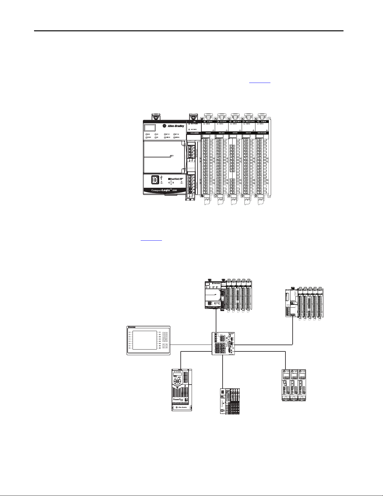
CompactLogix 5380 System
CompactLogix 5380 control systems are DIN rail-mounted systems that can
operate in various applications.
One of the simplest controller configurations is a standalone controller with
I/O assembled in one chassis, as shown in Figure 1
Figure 1 - CompactLogix 5380 Controller in a Standalone System
.
The controllers can also operate in more complex systems with devices that are
connected to the controller via an EtherNet/IP™ network, as shown in
Figure 2
.
Figure 2 - CompactLogix 5380 Controller in a More Complex System
Rockwell Automation Publication 5069-UM001G-EN-P - August 2020 15
Page 16
Chapter 1 CompactLogix 5380 and Compact GuardLogix 5380 Systems and Controllers
5069-L310ER-NSE No Stored Energy (NSE) Controller
The NSE controller is intended for use in applications that require the installed
controller to deplete its residual stored energy to specific levels before
transporting it into or out of your application.
The residual stored energy of the NSE controller depletes to 400μJ or less in 40
seconds.
WARNING: If your application requires the NSE controller to deplete its
residual stored energy to 400 μJ or less before you transport it into or out of
the application, complete these steps before you remove the controller.
1. Turn off power to the chassis.
2. Wait at least 40 seconds for the residual stored energy to decrease to
After you turn off power, the controller’s OK status indicator transitions
from Green to Solid Red to OFF.
400 μJ or less before you remove the controller.
There is no visual indication of when the 40 seconds has expired. You m ust
track that time period.
IMPORTANT The Real Time Clock (RTC) does not retain its time and date when the power
is off.
Some applications require that the installed controller to deplete its residual
stored energy to specific levels before transporting it into or out of your
application. This requirement can include other devices that also require a wait
time before removing them. See the documentation of those products for more
information.
CompactLogix 5380 Process controllers
CompactLogix 5380 Process controllers (5069-L320ERP, 5069-L340ERP) are
extensions of the Logix 5000 controller family that focus on plantwide process
control, and support motion.
The process controllers come configured with a default process tasking model
and dedicated PlantPAx® process instructions that are optimized for process
applications, and that improve design and deployment efforts.
The process controllers are conformal coated to add a layer of protection when
exposed to harsh, corrosive environments.
16 Rockwell Automation Publication 5069-UM001G-EN-P - August 2020
Page 17
CompactLogix 5380 and Compact GuardLogix 5380 Systems and Controllers Chapter 1
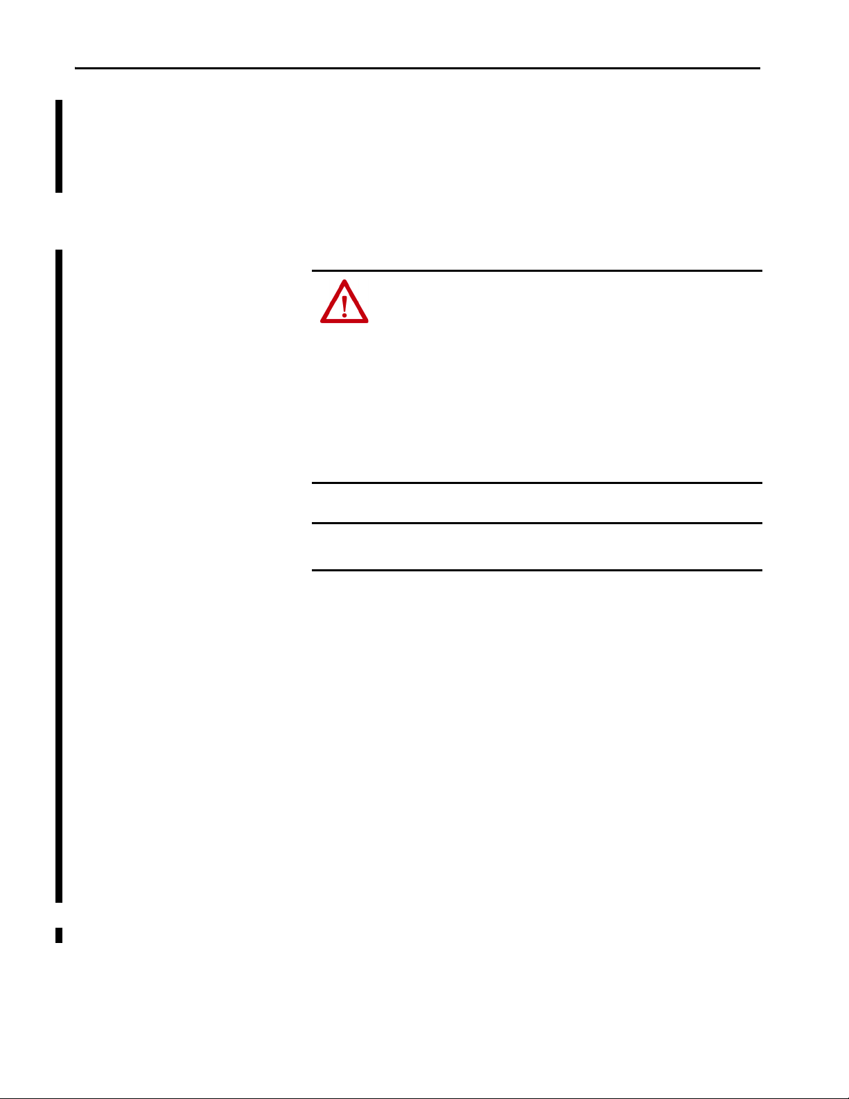
Compact GuardLogix 5380 System
Compact GuardLogix 5380 SIL 2 and SIL 3 controllers are programmable
automation controllers with integrated safety.
For SIL 3/PLe safety applications, the Compact GuardLogix 5380 SIL 3
controller system consists of a primary controller with an internal safety
partner, that function together in a 1oo2 architecture.
Compact GuardLogix 5380 SIL 2 Controller Compact GuardLogix 5380 SIL 3 Controller
For more information on safety ratings, see Safety Concept of Compact
GuardLogix 5380 Controllers on page 51.
The Compact GuardLogix system can communicate with safety I/O devices
via CIP Safety™ over an EtherNet/IP™ network (Guard I/O™ modules,
integrated safety drives, integrated safety components).
With a Compact GuardLogix controller, you can interface to standard I/O via
standard tasks while you interface with safety I/O via the safety task.
IMPORTANT For the safety task, Compact GuardLogix 5380 controllers support Ladder
Diagram only.
For standard tasks, Compact GuardLogix 5380 controllers support:
• Ladder Diagram (LD)
• Structured Text (ST)
• Function Block Diagram (FBD)
• Sequential Function Chart (SFC)
Rockwell Automation Publication 5069-UM001G-EN-P - August 2020 17
Page 18
Chapter 1 CompactLogix 5380 and Compact GuardLogix 5380 Systems and Controllers
Compact GuardLogix 5380 Controller Compact 5000 I/O Safety Digital, Standard Analog, and
Standard Digital Modules
Compact 5000 I/O EtherNet/IP Adapter
Compact 5000 I/O Analog, Digital, and
Safety Modules
PowerFlex® 527 Drive
(CIP Safety enabled)
Kinetix® 5500 Drives
(with Safe Torque
Off functionality)
1732ES ArmorBlock® Guard I/O™
Module
1734 POINT I/O Adapter
1734 POINT I/O Modules
1734 POINT Guard I/O™ Modules
Compact GuardLogix 5380 SIL 2 or SIL 3 Controller
Compact 5000 I/O Safety, Analog, and Digital
Modules
Compact 5000 I/O EtherNet/IP Adapter
Compact 5000 I/O Analog, Digital, and
Safety Modules
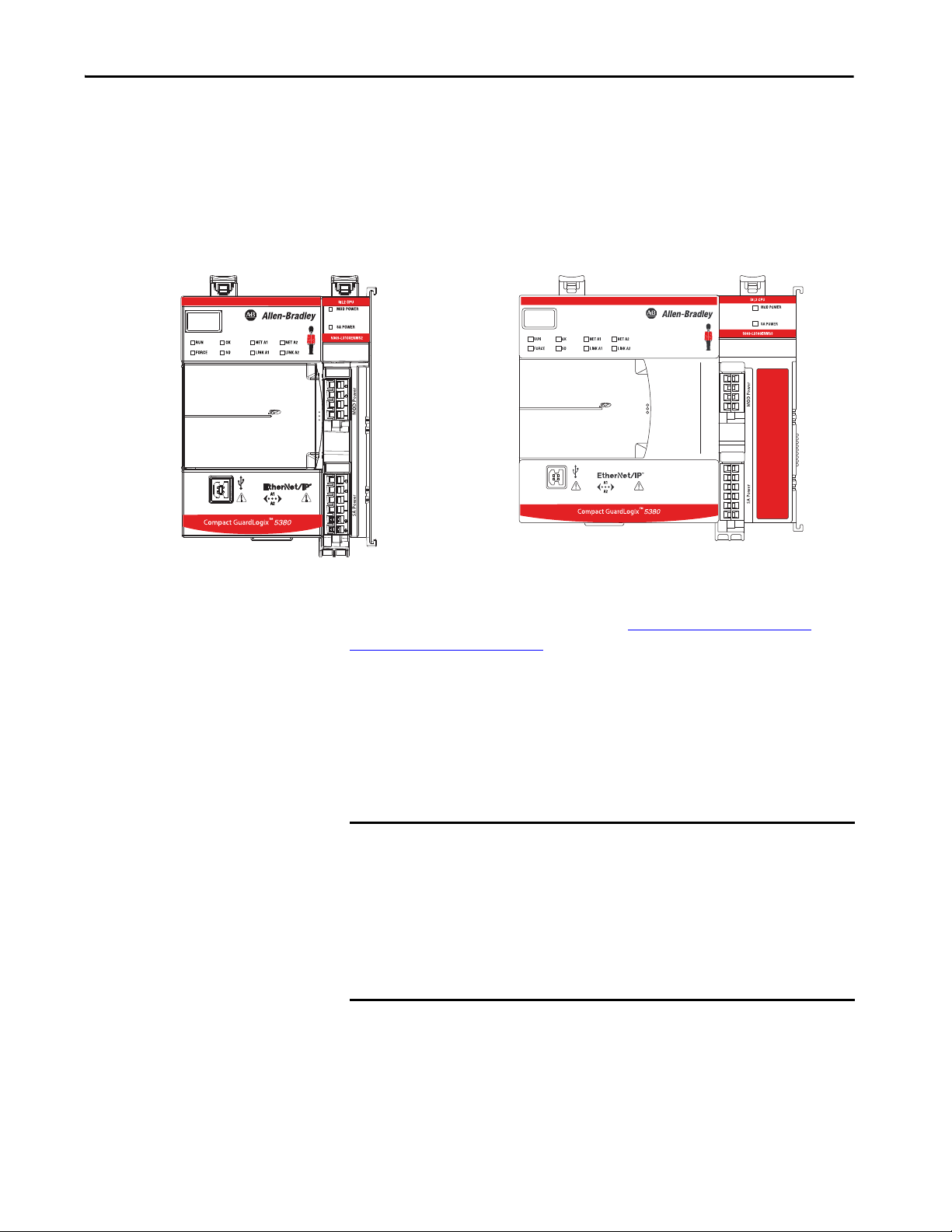
The controllers can operate in various applications that range from standalone
systems that contain local I/O modules, as shown in Figure 3
Figure 3 - Compact GuardLogix 5380 Controller in a Standalone System
The controllers can also operate in more complex systems with devices that are
connected to the controller via an EtherNet/IP network, as shown in Figure 4
.
.
Figure 4 - Compact GuardLogix 5380 Controller on an EtherNet/IP DLR Network
18 Rockwell Automation Publication 5069-UM001G-EN-P - August 2020
Page 19
CompactLogix 5380 and Compact GuardLogix 5380 Systems and Controllers Chapter 1
1791DS CompactBlock™
Guard I/O™ Module
DeviceNet Network
1788 EtherNet-to-DeviceNet
Linking Device
1732DS ArmorBlock
Guard I/O Module
1732DS ArmorBlock
Guard I/O Module
1791DS CompactBlock
Guard I/O Module
Compact GuardLogix 5380 SIL 2 or SIL 3 Controller
Compact 5000 I/O Safety, Analog, and Digital Modules
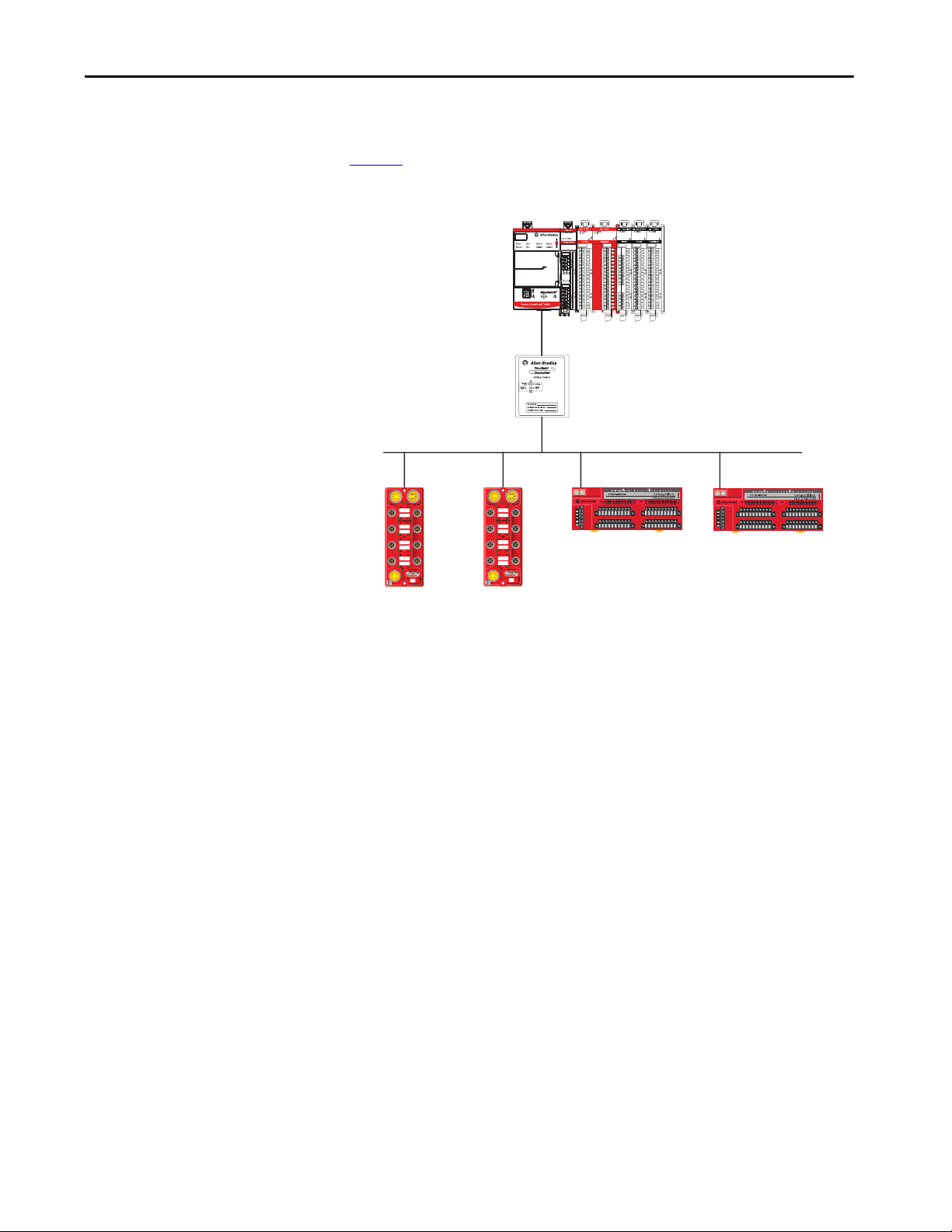
Compact GuardLogix 5380 controllers can communicate with safety devices
on a DeviceNet® network via a 1788-EN2DN linking device, as shown in
Figure 5
Figure 5 - Compact GuardLogix 5380 Controller Connected to Devices on a DeviceNet Network
Rockwell Automation Publication 5069-UM001G-EN-P - August 2020 19
Page 20
Chapter 1 CompactLogix 5380 and Compact GuardLogix 5380 Systems and Controllers
Design the System
Applies to these controllers:
CompactLogix 5380
Compact GuardLogix 5380 SIL 2
Compact GuardLogix 5380 SIL 3
When you design a system, you must decide what system components your
application needs. Ta b l e 1
describes components that are commonly used in
CompactLogix 5380 and Compact GuardLogix 5380 control systems.
Table 1 - System Components
Component Purpose Required For More Information
DIN rail Mounting system Yes • CompactLogix 5380 Controllers
End cap (5069-ECR)
IMPORTANT: The end cap ships with
the controller.
Removable terminal blocks (RTBs) Connect these power types to the controller:
External power supply
External power supply
Studio 5000 Logix Designer application Configure the project that is used to define
Linx-based communication software Used as follows:
ControlFLASH software Update controller firmware Yes • For compatible ControlFLASH software,
USB programming port Complete tasks that only require a temporary
Ethernet port A1 Connects to these network types:
Ethernet port A2 Connect to device-level networks —
Secure Digital (SD) card
IMPORTANT: The 1784-SD2 card ships
with the controller.
(1)
(1)
The end cap covers the exposed interconnections
on the last module in the system.
If you do not install the end cap before powering
the system, equipment damage or injury from
electric shock can result.
IMPORTANT: You install the end cap after the
last module is installed on the DIN rail. This
design helps to prevent the end cap from going
beyond the locked position.
If you push the end cap beyond the locked
position or insert it from the backwards direction,
you can damage the MOD power bus and SA
power bus connector.
•MOD power
•SA power
Provides Module (MOD) Power to the system Yes
Provides Senso r/Actuator (SA) Power to the
system
controller activity during system operation
• Assign the controller an IP address
• Maintain communication over the EtherNet/IP
network
connection to the controller, for example, when
you download a project or update firmware
•Enterprise-level network
•Device-level network
Store data, such as the controller project and
diagnostics that are required by technical support
to obtain information if non-recoverable
controller faults occur.
Yes
Yes
Yes - Only if the system requires
SA power.
If the system does not require SA
power, the external power supply
is not needed.
Yes • Minimum Requirements on page 13
Yes • For compatible Linx-based
— Connect a USB Cable on page 59
— Chapter 9, Use EtherNet/IP Modes on
We recommend that you leave the
SD card installed, so if a fault
occurs, diagnostic data is
automatically w ritten to the card.
Installation Instructions, publication
5069-IN013
• Compact GuardLogix 5380 SIL 2
Controllers Installation Instructions,
publication 5069-IN014
• Compact GuardLogix 5380 SIL 3
Controllers Installation Instructions,
publication 5069-IN023
Power the System on page 26
• Create a Logix Designer Application
Project on page 75
communication software and, see the
Product Compatibility and Download
Center (PCDC).
• Connect to the Controller on page 57
see the
Product Compatibility and Download
Center (PCDC).
• Update Controller Firmware on page 63
page 135
Use the Secure Digital Card on page 107
20 Rockwell Automation Publication 5069-UM001G-EN-P - August 2020
Page 21
CompactLogix 5380 and Compact GuardLogix 5380 Systems and Controllers Chapter 1
Table 1 - System Components (Continued)
Component Purpose Required For More Information
Ethernet cables Used as follows:
• Access the controller from the workstation
over an EtherNet/IP network to set IP address,
update firmware, download, and upload
projects
• Connect controller to an EtherNet/IP network
and perform tasks that are required for normal
operations
USB cable Access the controller directly from the
workstation to set IP address, update firmware,
download, and upload projects.
The USB port is intended for temporary local
programming purposes only and not intended for
permanent connection.
Integrated Safety I/O devices on an
EtherNet/IP network
Connected to safety input and output devices, for
example, Compact 5000 I/O safety modules or
Guardmaster® Multifunctional Access B ox.
IMPORTANT: CompactLogix 5380 controllers
cannot use safety devices.
Compact 5000 I/O modules Used as follows:
• Local standard I/O modules that are installed
in the CompactLogix 5380 system
• Remote standard I/O modules that are
accessible via the EtherNet/IP network
• Local safety I/O modules that are installed in
the CompactLogix 5380 system
• Remote safety I/O modules that are accessible
via the EtherNet/IP network
Devices that are installed on an
EtherNet/IP network
Dependent upon device type. Examples include:
• Remote standard I/O modules
• Remote safety I/O modules
• Ethernet switches
• Motion control devices, such as drives
• HMI devices
(1) We strongly recommend that you use separate external power supplies for MOD power and SA power, respectively.
Yes. Connect an Ethernet Cable on page 58
Yes - Only if you perform tasks
Connect a USB Cable on page 59
that are listed in the previous
column via the USB port.
You can also perform the tasks via
the controller Ethernet ports.
Yes for Compact GuardLogix 5380
Safety I/O Devices on page 191
controllers.
Yes • Standard I/O Modules on page 169
• Safety I/O Devices on page 191
Yes. • Standard I/O Modules on page 169
• Safety I/O Devices on page 191
• Develop Motion Applications on page 269
Rockwell Automation Publication 5069-UM001G-EN-P - August 2020 21
Page 22
Chapter 1 CompactLogix 5380 and Compact GuardLogix 5380 Systems and Controllers
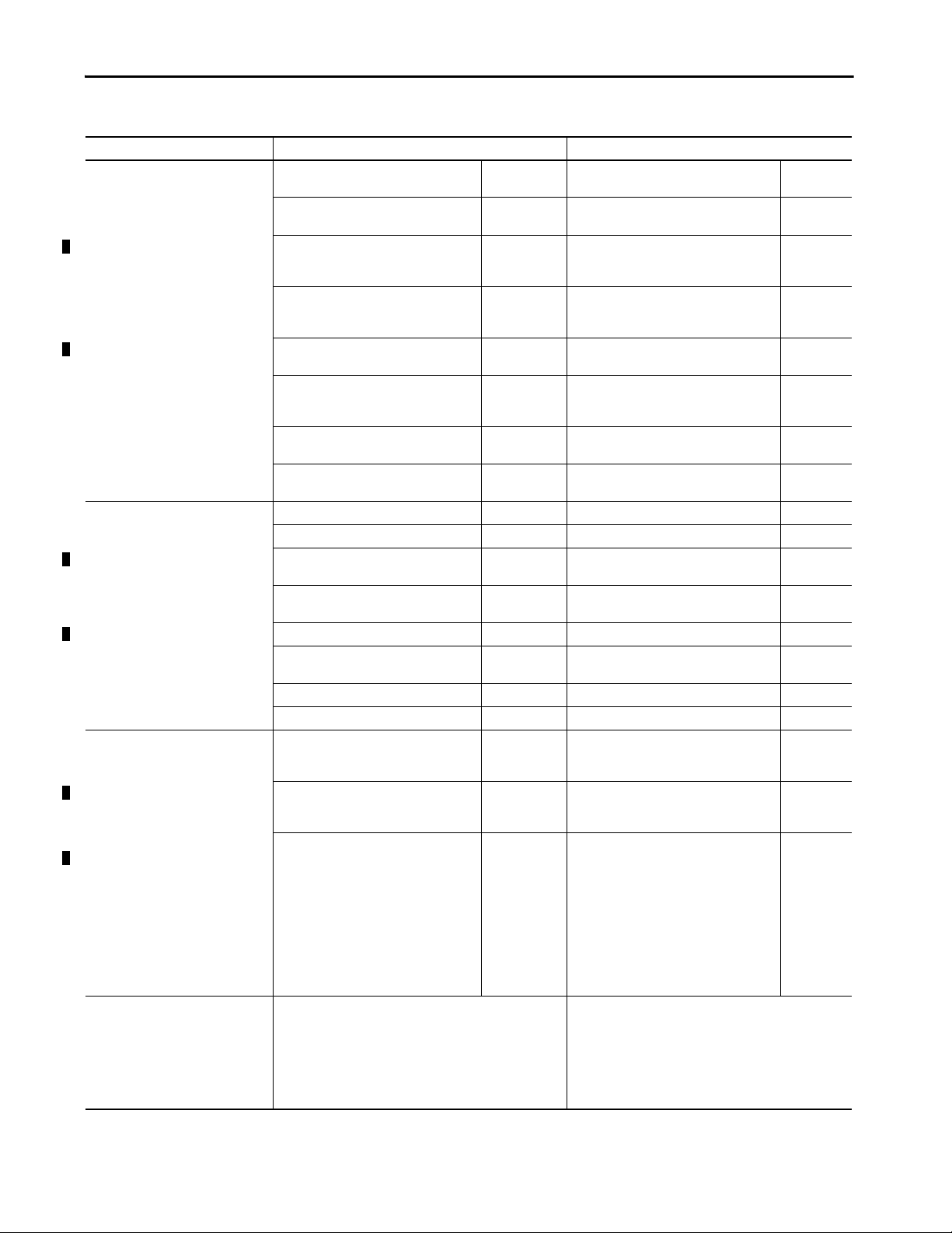
Controller Features
Ta b l e lists features available on the controllers. The features are described in
detail in the rest of this manual.
CompactLogix 5380 and Compact GuardLogix 5380 Controller Features
Feature CompactLogix 5380 Controllers Compact GuardLogix 5380 Controllers
User memory 5069-L306ER, 5069-L306ERM 0.6 MB 5069-L306ERS2, 5069-L306ERMS2,
5069-L310ER, 5069-L310ER-NSE, 5069L310ERM
5069-L320ER, 5069-L320ERM, 5069-L320ERP 2 MB 5069-L320ERS2, 5069-L320ERS2K,
5069-L330ER, 5069-L330ERM 3 MB 5069-L330ERS2, 5069-L330ERS2K,
5069-L340ER, 5069-L340ERM, 5069-L340ERP 4 MB 5069-L340ERS2, 5069-L340ERMS2,
5069-L350ERM 5 MB 5069-L350ERS2, 5069-L350ERS2K,
5069-L380ERM 8 MB 5069-L380ERS2, 5069-L380ERMS2,
5069-L3100ERM 10 MB 5069-L3100ERS2, 5069-L3100ERMS2,
Safety memory — 5069-L306ERS2, 5069-L306ERMS2,
Controller tasks • 32 tasks
Communication ports • 1 - USB port, 2.0 full-speed, Type B
EtherNet/IP network topologies
supported
EtherNet/IP modes • Linear/DLR mode
• 1000 programs/task
• Event tasks; all event triggers
• 2 - Embedded Ethernet ports, 10 Mbps, 100 Mbps, 1 Gbps
•Device Level Ring (DLR)
•Star
•Linear
• Dual-IP mode - Available with the Logix Designer application, version 29.00.00 or later.
1 MB 5069-L310ERS2, 5069-L310ERMS2,
5069-L306ERMS3
5069-L310ERMS3
5069-L320ERMS2, 5069-L320ERMS2K,
5069-L320ERMS3, 5069-L320ERMS3K
5069-L330ERMS2, 5069-L330ERMS2K,
5069-L330ERMS3, 5069-L330ERMS3K
5069-L340ERMS3
5069-L350ERMS2, 5069-L350ERMS2K,
5069-L350ERMS3, 5069-L350ERMS3K
5069-L380ERMS3
5069-L3100ERMS3
5069-L306ERMS3
— 5069-L310ERS2,
5069-L310ERMS2,
5069-L310ERMS3
— 5069-L320ERS2, 5069-L320ERS2K,
5069-L320ERMS2, 5069-L320ERMS2K,
5069-L320ERMS3, 5069-L320ERMS3K
— 5069-L330ERS2, 5069-L330ERS2K,
5069-L330ERMS2, 5069-L330ERMS2K,
5069-L330ERMS3, 5069-L330ERMS3K
— 5069-L340ERS2, 5069-L340ERMS2,
5069-L340ERMS3
— 5069-L350ERS2, 5069-L350ERS2K,
5069-L350ERMS2, 5069-L350ERMS2K,
5069-L350ERMS3, 5069-L350ERMS3K
— 5069-L380ERS2, 5069-L380ERMS2,
5069-L380ERMS3
— 5069-L3100ERS2, 5069-L3100ERMS2,
5069-L3100ERMS3
•32 tasks
31 standard tasks
1 safety task
• 1000 programs/task
• Event tasks; all event triggers
0.6 MB
1 MB
2 MB
3 MB
4 MB
5 MB
8 MB
10 MB
0.3 MB
0.5 MB
1 MB
1.5 MB
2 MB
2.5 MB
4 MB
5 MB
22 Rockwell Automation Publication 5069-UM001G-EN-P - August 2020
Page 23
CompactLogix 5380 and Compact GuardLogix 5380 Systems and Controllers Chapter 1
CompactLogix 5380 and Compact GuardLogix 5380 Controller Features (Continued)
Feature CompactLogix 5380 Controllers Compact GuardLogix 5380 Controllers
EtherNet/IP nodes supported, max
Integrated motion axes supported
Only controllers with an ‘M’ or ‘P’ in the
catalog number support motion.
Local I/O modules, max 5069-L306ER, 5069-L306ERM, 5069-L310ER,
Programming languages • Ladder Diagram (LD)
(1)
5069-L306ER, 5069-L306ERM 16 nodes 5069-L306ERS2, 5069-L306ERMS2,
5069-L306ERMS3
5069-L310ER, 5069-L310ER-NSE,
5069-L310ERM
24 nodes 5069-L310ERS2, 5069-L310ERMS2,
5069-L310ERMS3
5069-L320ER, 5069-L320ERM, 5069-L320ERP 40 nodes 5069-L320ERS2, 5069-L320ERS2K,
5069-L320ERMS2, 5069-L320ERMS2K
5069-L320ERMS3, 5069-L320ERMS3K
5069-L330ER, 5069-L330ERM 60 nodes 5069-L330ERS2, 5069-L330ERS2K,
5069-L330ERMS2, 5069-L330ERMS2K,
5069-L330ERMS3, 5069-L330ERMS3K
5069-L340ER, 5069-L340ERM, 5069-L340ERP 90 nodes 5069-L340ERS2, 5069-L340ERMS2,
5069-L340ERMS3
5069-L350ERM 120 nodes 5069-L350ERS2, 5069-L350ERS2K,
5069-L350ERMS2, 5069-L350ERMS2K,
5069-L350ERMS3, 5069-L350ERMS3K
5069-L380ERM 150 nodes 5069-L380ERS2, 5069-L380ERMS2,
5069-L380ERMS3
5069-L3100ERM 180 nodes 5069-L3100ERS2, 5069-L3100ERMS2,
5069-L3100ERMS3
5069-L306ERM 2 axes 5069-L306ERMS2, 5069-L306ERMS3 2 axes
5069-L310ERM 4 axes 5069-L310ERMS2, 5069-L310ERMS3 4 axes
5069-L320ERM, 5069-L320ERP 8 axes 5069-L320ERMS2, 5069-L320ERMS2K,
5069-L320ERMS3, 5069-L320ERMS3K,
5069-L330ERM 16 axes 5069-L330ERMS2, 5069-L330ERMS2K,
5069-L330ERMS3, 5069-L330ERMS3K
5069-L340ERM, 5069-L340ERP 20 axes 5069-L340ERMS2, 5069-L340ERMS3 20 axes
5069-L350ERM 24 axes 5069-L350ERMS2, 5069-L350ERMS2K,
5069-L350ERMS3, 5069-L350ERMS3K
5069-L380ERM 28 axes 5069-L380ERMS2, 5069-L380ERMS3 28 axes
5069-L3100ERM 32 axes 5069-L3100ERMS2, 5069-L3100ERMS3 32 axes
8 modules 5069-L306ERS2, 5069-L306ERMS2,
5069-L310ER-NSE, 5069-L310ERM
5069-L306ERMS3, 5069-L310ERS2,
5069-L310ERMS2, 5069-L310ERMS3
5069-L320ER, 5069-L320ERM, 5069-L320ERP 16 modules 5069-L320ERS2, 5069-L320ERS2K,
5069-L320ERMS2, 5069-L320ERMS2K,
5069-L320ERMS3, 5069-L320ERMS3K
(2)
5069-L330ER
, 5069-L330ERM
5069-L340ER, 5069-L340ERM, 5069-L340ERP,
5069-L350ERM, 5069-L380ERM,
5069-L3100ERM
(2)
,
31 modules 5069-L330ERS2, 5069-L330ERS2K,
5069-L330ERMS2, 5069-L330ERMS2K,
5069-L330ERMS3, 5069-L330ERMS3K,
5069-L340ERS2, 5069-L340ERMS2,
5069-L340ERMS3, 5069-L350ERS2,
5069-L350ERS2K,5069-L350ERMS2,
5069-L350ERMS2K, 5069-L350ERMS3,
5069-L350ERMS3K, 5069-L380ERS2,
5069-L380ERMS2, 5069-L380ERMS3,
5069-L3100ERS2, 5069-L3100ERMS2,
5069-L3100ERMS3
• For the safety task, Compact GuardLogix controllers support
• Structured Text (ST)
• Function Block Diagram (FBD)
• Sequential Function Char t (SFC)
Ladder Diagram only.
• For standard tasks, Compact GuardLogix controllers support:
– Ladder Diagram (LD)
– Structured Text (ST)
– Function Block Diagram (FBD)
– Sequential Function Chart (SFC)
16 nodes
24 nodes
40 nodes
60 nodes
90 nodes
120 nodes
150 nodes
180 nodes
8 axes
16 axes
24 axes
8 modules
16 modules
31 modules
Rockwell Automation Publication 5069-UM001G-EN-P - August 2020 23
Page 24

Chapter 1 CompactLogix 5380 and Compact GuardLogix 5380 Systems and Controllers
CompactLogix 5380 and Compact GuardLogix 5380 Controller Features (Continued)
Feature CompactLogix 5380 Controllers Compact GuardLogix 5380 Controllers
Supported Controller Features • Data access control
• Firmware Supervisor
• Secure Digital (SD) card
• Standard Connections
(1) A node is an EtherNet/IP device that you add directly to the I/O configuration, and counts toward the node limits of the controller. For more information on EtherNet/IP nodes, see page 121.
(2) When you use this controller with the Logix Designer application, version 29.00.00, the application limits the number of local I/O modules in the project to 16. For more information, see
Knowledgebase Article 5380 CompactLogix controllers limited to 16 local Compact 5000 I/O modules in V29 of Studio 5000.®
With the Logix Designer application, version 30.00.00 or later, the controller supports as many as 31 local I/O modules.
• Data access control
• Firmware Supervisor
• Secure Digital (SD) card
• Standard Connections
• Safety Connections
IMPORTANT When you use a CompactLogix 5380 or Compact GuardLogix 5380 controller,
you do not need to configure a System Overhead Time Slice value.
24 Rockwell Automation Publication 5069-UM001G-EN-P - August 2020
Page 25
CompactLogix 5380 and Compact GuardLogix 5380 Systems and Controllers Chapter 1
Features Supported by Compact GuardLogix 5380 Controllers Via the Safety Task
You can use the Compact GuardLogix 5380 controllers in safety applications
via the Safety task in the Logix Designer application.
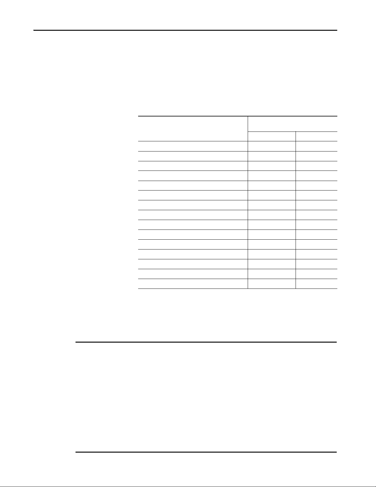
In the Logix Designer application, the Safety task supports a subset of features
that are supported in the standard task as listed in this table.
Feature Studio 5000 Logix Designer Application,
Add-On Instructions X X
Instruction-based alarms and events — X
Tag-based alarms — X
Contro ller lo gging X X
(1)
Event ta sks
Function Block Diagrams (FBD) — X
Integrated motion X
Drive Safety Instructions X —
Ladder Diagram (LD) X X
Language switching X X
License-based source protection — X
Import program components — X
Export program components X X
Sequential Function Chart (SFC) routines — X
Structured Text (ST ) — X
(1) While the safety task cannot be an Event task, standard Event tasks can be triggered with the use of the Event instruction in the
safety task.
(2) Compact GuardLogix 5380 SIL 2 controllers are compatible with Studio 5000 Logix Designer Application, version 31 or later.
Compact GuardLogix 5380 SIL 3 controllers are compatible with Studio 5000 Logix Designer Application, Version 32 or later
(3) Limited to the use of Drive Safety Instructions wi th Kinetix 5700 ERS4 drives.
Version 31 or Later
Sa fety Task St anda rd Tas k
—X
(3)
(2)
X
IM PORTANT Safety Consideration
Compact GuardLogix 5380 controllers can produce standard tags as unicast or multicast, but they can only
produce safety tags as unicast. The controllers can consume safety tags as either unicast or multicast.
When you configure a produced safety tag, you are only allowed to configure unicast connection options.
Logix Designer does not allow you to configure multicast connection options.
When you configure a consumed tag, you must consider the capabilities of the producer:
• If the producer in the I/O tree of this controller is a GuardLogix 5580 or Compact GuardLogix 5380
controller, and you are consuming a safety tag, you must configure the consumed tag to use unicast.
• If the producer in the I/O tree of this controller is a GuardLogix 5570 or GuardLogix 5560 controller, or a
Compact GuardLogix 5370 controller, the safety consumed tag can be configured as either unicast or
multicast. A GuardLogix 5560 controller requires Studio 5000 Logix Designer application version
19.00.00 or later for unicast produce/consume safety tags.
Rockwell Automation Publication 5069-UM001G-EN-P - August 2020 25
Page 26

Chapter 1 CompactLogix 5380 and Compact GuardLogix 5380 Systems and Controllers
Power the System
Applies to these controllers:
CompactLogix 5380
Compact GuardLogix 5380 SIL 2
Compact GuardLogix 5380 SIL 3
The controller provides power to the system as follows:
• MOD Power - System-side power that powers the system and lets
modules transfer data and execute logic.
System-side power is provided through the MOD Power RTB.
• SA Power - Field-side power that powers some Compact 5000 I/O
modules and field-side devices that are connected to them.
Field-side power is provided through the SA Power RTB.
There are specific considerations and restrictions that you must be aware of
before you connect MOD power and SA power to a CompactLogix 5380
system or to a Compact GuardLogix 5380 system.
For more information on how to connect MOD power and SA power to the
different systems, see the following:
• How to Power CompactLogix 5380 Controllers - Chapter 2 on page 27
• How to Power Compact GuardLogix 5380 Controllers - Chapter 3 on
page 37
26 Rockwell Automation Publication 5069-UM001G-EN-P - August 2020
Page 27
Chapter 2
How to Power CompactLogix 5380 Controllers
Top ic Pag e
Two Type s of Powe r 27
MOD Power 29
SA Power 30
This chapter explains how to power standard CompactLogix™ 5380
controllers.
For information on how to power Compact GuardLogix® 5380 controllers, see
Chapter 3, How to Power Compact GuardLogix 5380 Controllers on page 37
.
Two Types of Power
Applies to these controllers:
CompactLogix 5380
The CompactLogix 5380 controllers provide power to the system as follows:
• MOD Power - System-side power that powers the system and lets
modules transfer data and execute logic.
System-side power is provided through the MOD Power RTB.
• SA Power - Field-side power that powers some Compact 5000™ I/O
modules and field-side devices that are connected to them.
Field-side power is provided through the SA Power RTB.
Rockwell Automation Publication 5069-UM001G-EN-P - August 2020 27
Page 28
Chapter 2 How to Power CompactLogix 5380 Controllers
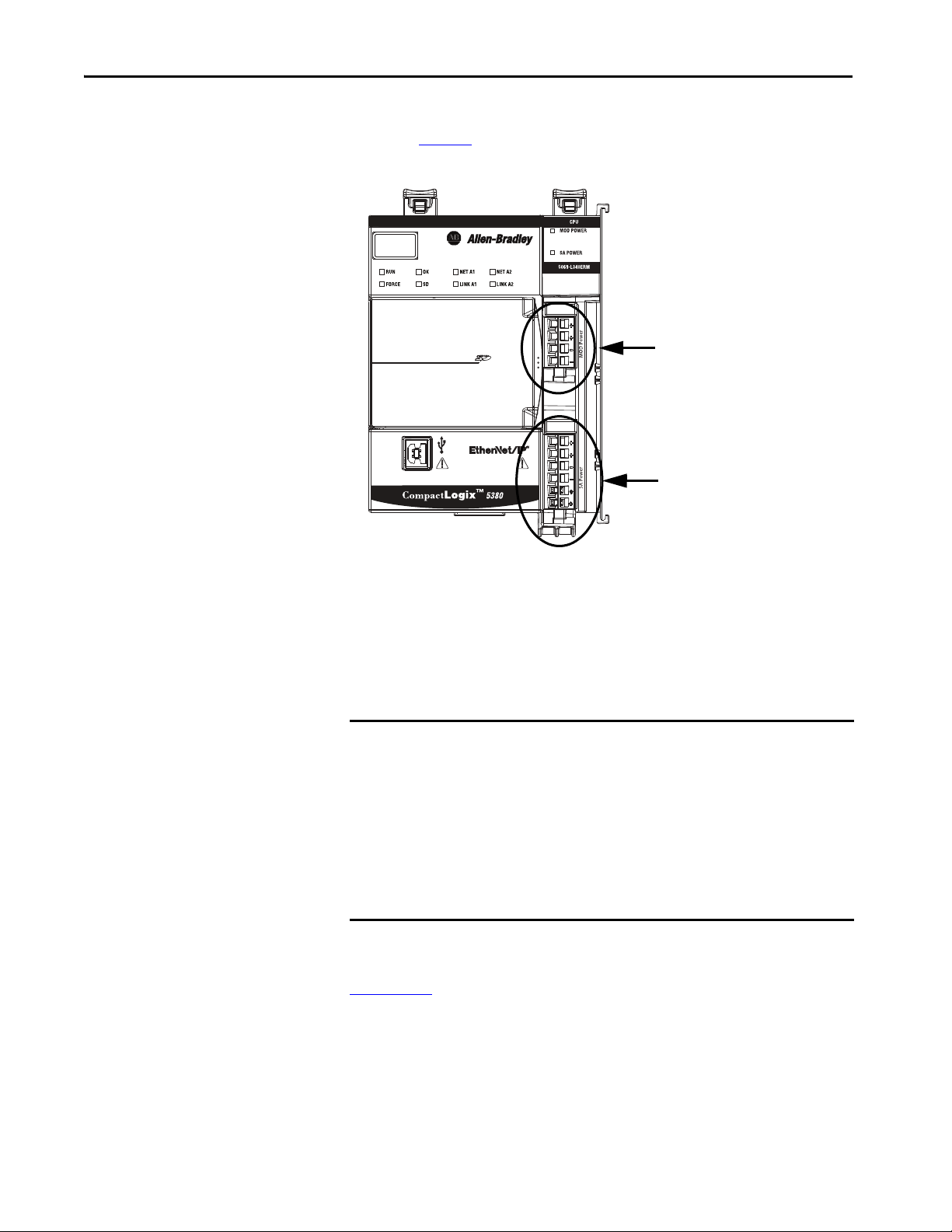
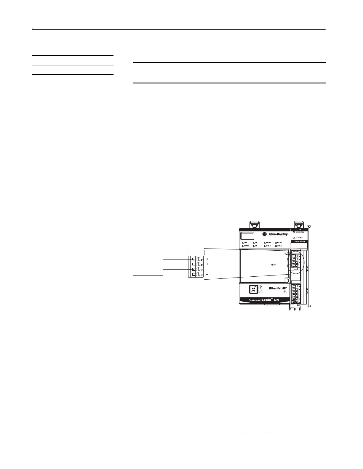
MOD Power
Connection
SA Power
Connection
Connect external power supplies to the RTBs to provide MOD power and
SA power. Figure 6
Figure 6 - MOD Power and SA Power RTBs on a CompactLogix 5380 Controller
shows the RTBs on a CompactLogix 5380 controller.
Power begins at the controller and passes across the Compact 5000 I/O
module internal circuitry via power buses.
MOD power passes across a MOD power bus, and SA power passes across a SA
power bus. The MOD power bus and SA power bus are isolated from each
other.
IMPORTANT We recommend that you use separate external power supplies for MOD
power and SA power, respectively. This practice can help prevent unintended
consequences that can result if you use one supply.
If you use separate external power supplies, the loss of power from one
external power supply does not affect the availability of power from the
other supply. For example, if separate MOD and SA external power supplies
are used and SA power is lost, MOD power remains available for the
CompactLogix 5380 controller and Compact 5000 I/O modules. As such, data
transfer continues in the system.
For more information on how to connect MOD power and SA power, see the
CompactLogix 5380 Controllers Installation Instructions, publication
5069-IN013
28 Rockwell Automation Publication 5069-UM001G-EN-P - August 2020
Page 29
How to Power CompactLogix 5380 Controllers Chapter 2
24V DC
Power
Supply
+
–
MOD Power
Applies to these controllers:
CompactLogix 5380
MOD power is a DC power source that is required to operate a
CompactLogix 5380 system.
IMPORTANT You can only use DC power on the MOD power bus. Do not connect AC power
to the MOD power bus.
Remember the following:
• Every module in the CompactLogix 5380 system draws current from the
MOD power bus and passes the remaining current to the next module.
• MOD power lets Compact 5000 I/O modules transfer data and the
controller execute logic.
• A CompactLogix 5380 system uses only one MOD power bus.
• The total continuous current draw across the MOD power bus must not
be more than 10 A, max, at 18...32V DC.
• We recommend that you use an external power supply that is adequately
sized for the total MOD power bus current draw in the system.
Yo u m us t co ns id er inrush current requirements when you calculate the
total MOD power bus current draw in the system.
Figure 7 - External Power Supply Provides MOD Power
MOD Power Bus
When the MOD power source is turned on, the following occurs.
1. The CompactLogix 5380 controller draws current from the MOD
power bus and passes the remaining current through to the next module.
2. The next module draws MOD power bus current and passes the
remaining current through to the next module.
3. The process continues until MOD power bus current needs are met for
all modules in the system.
For more information on the current that the Compact 5000 I/O modules
draw from the MOD power bus, see the Compact 5000 I/O Modules
Specifications Technical Data, publication 5069-TD001
Rockwell Automation Publication 5069-UM001G-EN-P - August 2020 29
.
Page 30

Chapter 2 How to Power CompactLogix 5380 Controllers
SA Power
Applies to these controllers:
CompactLogix 5380
SA power provides power to devices that are connected to some of the
Compact 5000 I/O modules in the CompactLogix 5380 system. SA power is
connected to the controller via an SA power RTB.
Remember the following:
• Some Compact 5000 I/O modules draw current from the SA power bus
and pass the remaining current to the next module.
• Some Compact 5000 I/O modules only pass current along the SA
power bus to the next module.
• A CompactLogix 5380 system can have multiple SA power buses. The
first SA power bus starts at the controller and passes across the I/O
modules that are installed to the right of the controller.
You use a 5069-FPD field potential distributor to establish a new SA
power bus. The new SA power bus is isolated from the SA power bus to
its left in the system.
For more information on how to use a 5069-FPD field potential
distributor in a CompactLogix 5380 system, see page 34
.
• If the SA power source uses DC voltage, the total continuous current
draw across the SA power bus must not be more than to 10 A, max at
18…32V DC.
• We recommend that you use an external power supply that is adequately
sized for the total SA power bus current draw on an individual bus.
Yo u m us t co ns id er inrush current requirements when you calculate the
total SA power bus current draw in the system.
30 Rockwell Automation Publication 5069-UM001G-EN-P - August 2020
Page 31

How to Power CompactLogix 5380 Controllers Chapter 2
AC or DC
Power
Supply
+
–
• Connections to an SA power bus use a shared common. All inputs that
draw current from an SA power bus to power field-side devices have a
return through circuitry to the SA - terminal on the SA power
connector.
IMPORTANT Each SA power bus has a shared common unique to that bus
because SA power buses are completely isolated from each other.
That is, the SA power bus that the CompactLogix 5380 controller
establishes has a shared common. If you use a 5069-FPD field
potential distributor to establish a new SA power bus in the system,
that second bus has its own shared common for modules that draw
current from it.
Figure 8 - External Power Supply Provides SA Power
When the SA power source is turned on, the following occurs.
1. The CompactLogix 5380 controller draws current from the SA power
bus and passes the remaining current through to the next module.
IMPORTANT The level of current that the CompactLogix 5380 controller draws
from the SA power bus is negligible.
It draws 10 mA (DC Power), 25 mA (AC power).
2. The next module completes one of these tasks.
– If the module uses SA power, the module draws current from the SA
power bus and passes the remaining current through to the next
module.
– If the module does not use SA power bus current, the module passes
the remaining current through to the next module.
3. The process continues until all SA power bus current needs are met for
the modules on the SA power bus.
Rockwell Automation Publication 5069-UM001G-EN-P - August 2020 31
Page 32

Chapter 2 How to Power CompactLogix 5380 Controllers
If your system includes AC and DC modules that require SA power, you must
use a 5069-FPD field potential distributor to establish a separate SA power bus
and separate the module types on the isolated SA power buses.
For more information on the current that the Compact 5000 I/O modules
draw from the SA power bus, see the Compact 5000 I/O Modules
Specifications Technical Data, publication 5069-TD001
.
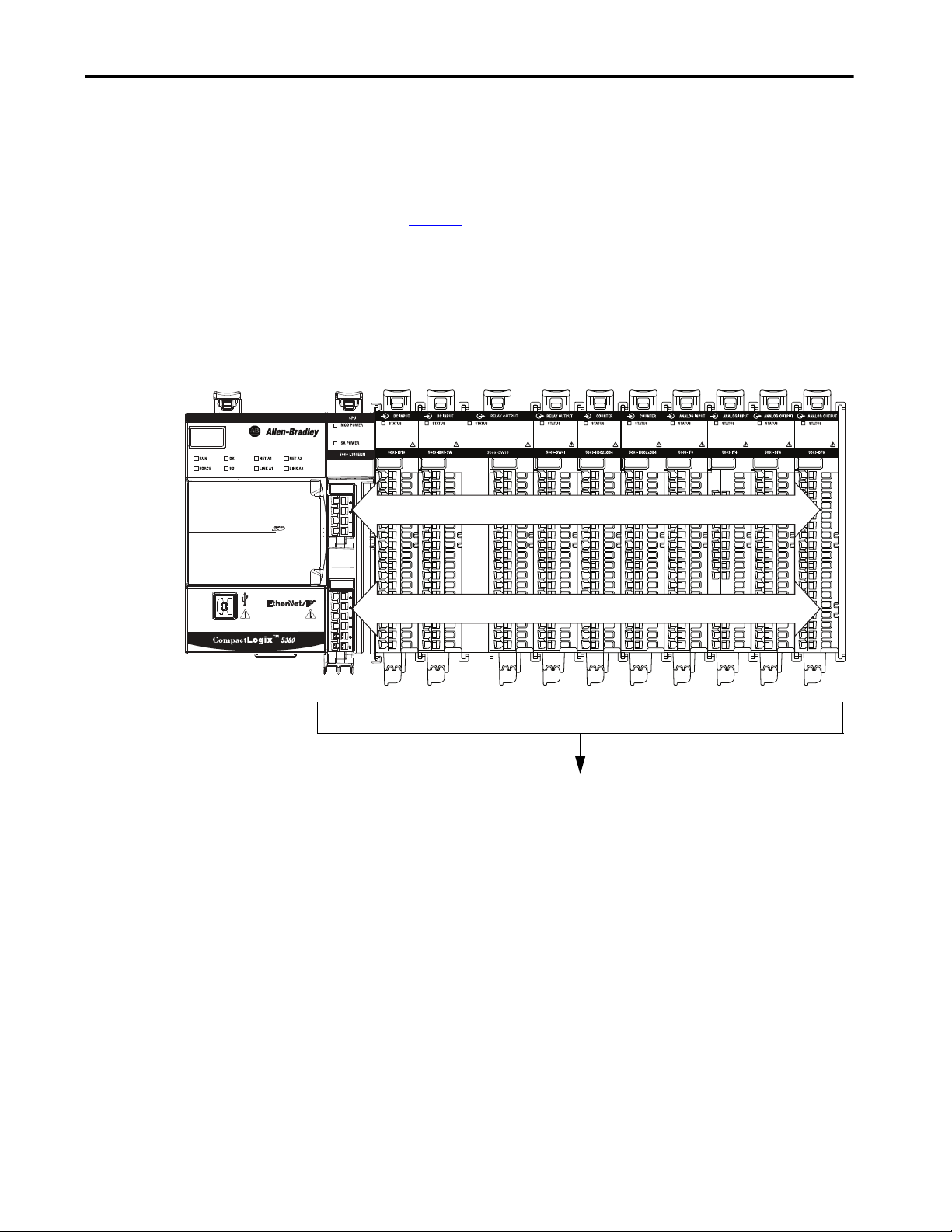
Track SA Power Bus Current Draw
We recommend that you track the SA power bus current draw, max, per
module, and collectively for the CompactLogix 5380 system.
You must make sure that the Compact 5000 I/O modules that are installed on
an SA power bus do not consume more than 10 A. If so, you must establish
another SA power bus.
Consider the following with this example:
• The values in this example represent a worst-case calculation. That is, all
modules that draw SA power bus current, draw the maximum available
on the module.
• Not all modules that are shown in Figure 9
use SA power bus current.
For example, the 5069-ARM and 5069-OW4I modules only pass SA
power bus current to the next module.
Other modules that do not use SA power bus current, but are not shown
in the graphic, include the 5069-OB16, 5069-OB16F, 5069-OX4I, and
5069-SERIAL modules.
32 Rockwell Automation Publication 5069-UM001G-EN-P - August 2020
Page 33
How to Power CompactLogix 5380 Controllers Chapter 2
Continuous MOD Power Bus Limited to 10 A, Max
Continuous SA Power Bus Limited to 10 A, Max
SA Power Bus Current, Max,
Per Mo dule
10 mA
System SA Power Bus Current, Max = 7.160 A
200 mA 200 mA 150 mA 0 mA 3 A 3 A 100 mA 100 mA 150 mA 250 mA
• System SA power bus current, max, is calculated as each module draws
SA power bus current. The calculation begins with the controller. The
controller SA power bus current draw used for the calculation is 10 mA
for DC power
In Figure 9
, after the 5069-IB16 module in slot 1 draws SA power bus
current, the system SA power bus current, max, is 210 mA.
After the 5069-IB16 module in slot 2 draws SA power bus current, the
system SA power bus current draw is 410 mA. This process continues
until the system SA power bus current, max, is 7.160 A.
Figure 9 - CompactLogix 5380 System - Calculate SA Power Bus Current Draw
Rockwell Automation Publication 5069-UM001G-EN-P - August 2020 33
Page 34
Chapter 2 How to Power CompactLogix 5380 Controllers
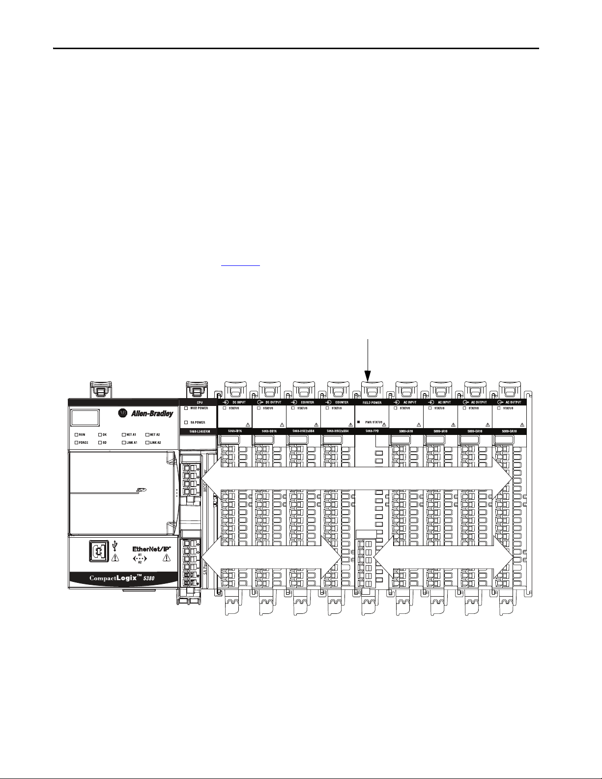
MOD Power Bus
First SA Power Bus Second SA Power Bus
5069-FPD Field Potential Distributor
Use a 5069-FPD Field Potential Distributor to Create a New SA Power Bus
You can use a 5069-FPD field potential distributor to establish a new SA power
bus in a CompactLogix 5380 system.
The field potential distributor blocks the current that passes across the SA
power bus to its left. At that point, the field potential distributor establishes a
new SA power bus for modules to the right. The new SA power bus is isolated
from the SA power bus to its left in the system.
You can connect either a 24V DC or 120/240V AC external power supply to a
5069-FPD field potential distributor in a CompactLogix 5380 system.
Figure 10
shows a CompactLogix 5380 system that uses a 5069-FPD field
potential distributor to create a second SA power bus.
Figure 10 - CompactLogix 5380 System - Create a New SA Power Bus
You can install multiple 5069-FPD field potential distributors in the same
system, if necessary.
34 Rockwell Automation Publication 5069-UM001G-EN-P - August 2020
Page 35

How to Power CompactLogix 5380 Controllers Chapter 2
SA Power - Additional Notes
• Other examples of system configurations that use multiple SA power
buses include:
– The modules in the system collectively draw more than 10 A of SA
power. That is, the maximum current that one SA power bus
can provide.
– The modules in the system must be isolated according to module
types, such as digital I/O and analog I/O modules.
– The modules in the system are isolated according to the type of
field-side device to which they are connected.
For example, you can separate modules that are connected to fieldside devices that use DC voltage from modules that are connected to
field-side devices that require AC voltage.
• The actual current in CompactLogix 5380 system changes based on the
operating conditions at a given time.
For example, the SA power bus current draw on some modules is
different if all channels power field devices or half of the channels power
field devices.
• Some Compact 5000 I/O modules use field-side power but do not draw
it from a SA power bus. The modules receive field-side power from an
external power supply that is connected directly to the I/O module.
For example, the 5069-OB16 and 5069-OB16F modules use Local
Actuator (LA) terminals on the module RTB, that is, LA+ and LA–
terminals for all module channels.
In this case, you can use the same external power supply that is
connected to the SA power RTB on the controller to the LA+ and LA–
terminals.
IMPORTANT You must consider the current limit of an external power supply if
you use it to provide power to the SA power RTB on the controller
and the LA+ and LA– terminals on a 5069-OB16 or 5069-OB16F
module.
Rockwell Automation Publication 5069-UM001G-EN-P - August 2020 35
Page 36

Chapter 2 How to Power CompactLogix 5380 Controllers
Notes:
36 Rockwell Automation Publication 5069-UM001G-EN-P - August 2020
Page 37
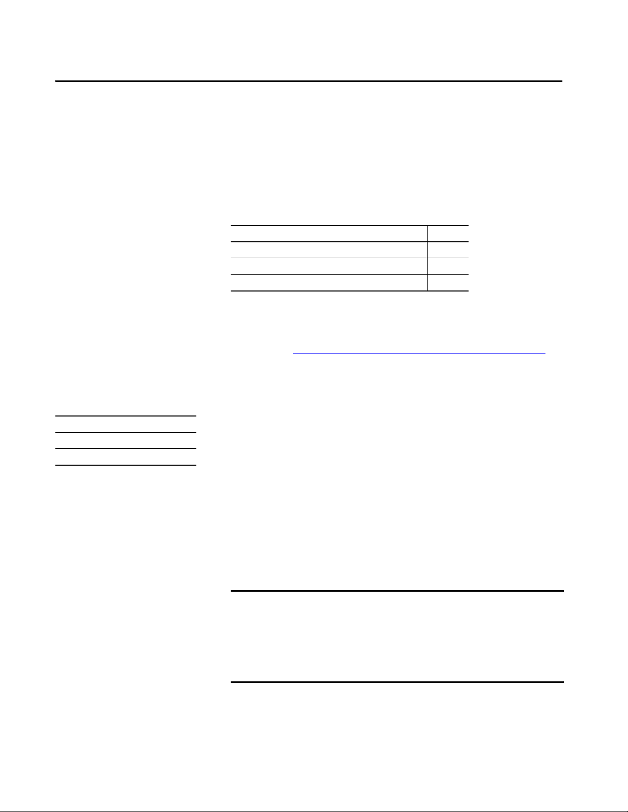
Chapter 3
How to Power Compact GuardLogix 5380
Controllers
Top ic Pag e
Two Type s of Powe r 37
MOD Power 39
SA Power 41
This chapter explains how to power Compact GuardLogix® 5380 controllers.
For information on how to power standard CompactLogix™ 5380 controllers,
see Chapter 2, How to Power CompactLogix 5380 Controllers on page 27
.
Two Types of Power
Applies to these controllers:
Compact GuardLogix 5380 SIL 2
Compact GuardLogix 5380 SIL 3
The Compact GuardLogix 5380 controllers provide power to the system
as follows:
• MOD Power - System-side power that powers the system and lets
modules transfer data and execute logic.
System-side power is provided through the MOD Power RTB.
• SA Power - Field-side power that powers some Compact 5000™ I/O
modules and field-side devices that are connected to them.
Field-side power is provided through the SA Power RTB.
IMPORTANT Both the MOD and SA Power must be DC power on the controller side.
DC power for the Compact GuardLogix controllers must come from an
SELV/PELV-rated power source.
If you use an AC voltage for local I/O modules, then you must connect
through a 5069-FPD field potential distributor module. An AC voltage cannot
be terminated on the controller.
Rockwell Automation Publication 5069-UM001G-EN-P - August 2020 37
Page 38

Chapter 3 How to Power Compact GuardLogix 5380 Controllers
MOD Power
Connection
SA Power
Connection
MOD Power
Connection
SA Power
Connection
Connect external power supplies to the RTBs to provide MOD power and
SA power. Figure 11
controller.
Figure 11 - MOD and SA Power RTBs on Compact GuardLogix 5380 SIL2 and SIL 3 Controllers
shows the RTBs on a Compact GuardLogix 5380
Power begins at the controller and passes across the Compact 5000 I/O
module internal circuitry via power buses.
MOD power passes across a MOD power bus, and SA power passes across a SA
power bus. The MOD power bus and SA power bus are isolated from each
other.
IMPORTANT We recommend that you use separate external power supplies for MOD
power and SA power, respectively. This practice can help prevent unintended
consequences that can result if you use one supply.
If you use separate external power supplies, the loss of power from one
external power supply does not affect the availability of power from the
other supply. For example, if separate MOD and SA external power supplies
are used and SA power is lost, MOD power remains available for the Compact
GuardLogix 5380 controller and Compact 5000 I/O modules. As such, data
transfer continues in the system.
For more information on how to connect MOD power and SA power, see
these publications:
• Compact GuardLogix 5380 SIL2 Controllers Installation Instructions,
publication 5069-IN014.
• Compact GuardLogix 5380 SIL3 Controllers Installation Instructions,
publication 5069-IN023.
38 Rockwell Automation Publication 5069-UM001G-EN-P - August 2020
Page 39

How to Power Compact GuardLogix 5380 Controllers Chapter 3
24V DC
SELV/PELV-listed
power supply
+
–
24V DC
SELV/PELV-listed
power supply
+
–
MOD Power
Applies to these controllers:
Compact GuardLogix 5380 SIL 2
Compact GuardLogix 5380 SIL 3
MOD power is a DC power source that is required to operate a Compact
GuardLogix 5380 system. Remember the following:
• You must use SELV or PELV power supplies to provide MOD power to
Compact GuardLogix 5380 controllers.
• Every module in the Compact GuardLogix 5380 system draws current
from the MOD power bus and passes the remaining current to the next
module.
• MOD power lets Compact 5000 I/O modules transfer data and the
controller execute logic.
• A Compact GuardLogix 5380 system uses only one MOD power bus.
• You must limit the MOD power source to 5 A, max, at 18...32V DC.
• We recommend that you use an external SELV/PELV rated power
supply that is adequately sized for the total MOD power bus current
draw in the system. You must consider current inrush requirements
when you calculate the total MOD power bus current draw in the
system.
Figure 12 - External Power Supply Provides MOD Power
Rockwell Automation Publication 5069-UM001G-EN-P - August 2020 39
Page 40

Chapter 3 How to Power Compact GuardLogix 5380 Controllers
MOD Power Bus
When the MOD power source is turned on, the following occurs.
For more information on the current that the Compact 5000 I/O modules
draw from the MOD power bus, see the Compact 5000 I/O Modules
Specifications Technical Data, publication 5069-TD001
1. The Compact GuardLogix 5380 controller draws current from the
MOD power bus and passes the remaining current through to the next
module.
2. The next module draws MOD power bus current and passes the
remaining current through to the next module.
3. The process continues until MOD power bus current needs are met for
all modules in the system.
.
40 Rockwell Automation Publication 5069-UM001G-EN-P - August 2020
Page 41

How to Power Compact GuardLogix 5380 Controllers Chapter 3
SA Power
Applies to these controllers:
Compact GuardLogix 5380 SIL 2
Compact GuardLogix 5380 SIL 3
SA power provides power to devices that are connected to some of the
Compact 5000 I/O modules in the Compact GuardLogix 5380 system. SA
power is connected to the controller via an SA power RTB.
Remember the following:
IMPORTANT More specific restrictions apply when you connect SA power to a
Compact GuardLogix 5380 controller or 5069-FPD field potential distributor.
For more information, see page 46
.
• You must use SELV or PELV power supplies to provide SA power to
Compact GuardLogix 5380 controllers.
• If the SA power source uses DC voltage, you must limit the SA power
source to 10 A, max at 18…32V DC.
• Some Compact 5000 I/O modules draw current from the SA power bus
and pass the remaining current to the next module.
• Some Compact 5000 I/O modules only pass current along the SA
power bus to the next module.
• If the SA power source is an AC power supply, or non-SELV/PELV DC
source, then you must terminate from an FPD before consuming the
power on the SA power bus.
• A Compact GuardLogix 5380 system can have multiple SA power buses.
The first SA power bus starts at the controller and passes across the I/O
modules that are installed to the right of the controller.
You can use a 5069-FPD field potential distributor to establish a new SA
power bus. The new SA power bus is isolated from the SA power bus to
its left in the system.
For more information on how to use a 5069-FPD field potential
distributor in a CompactLogix 5380 system, see page 45
.
• We recommend that you use an external power supply that is adequately
sized for the total SA power bus current draw on an individual bus. You
must consider current inrush requirements when you calculate the
total SA power bus current draw on a specific bus.
Rockwell Automation Publication 5069-UM001G-EN-P - August 2020 41
Page 42
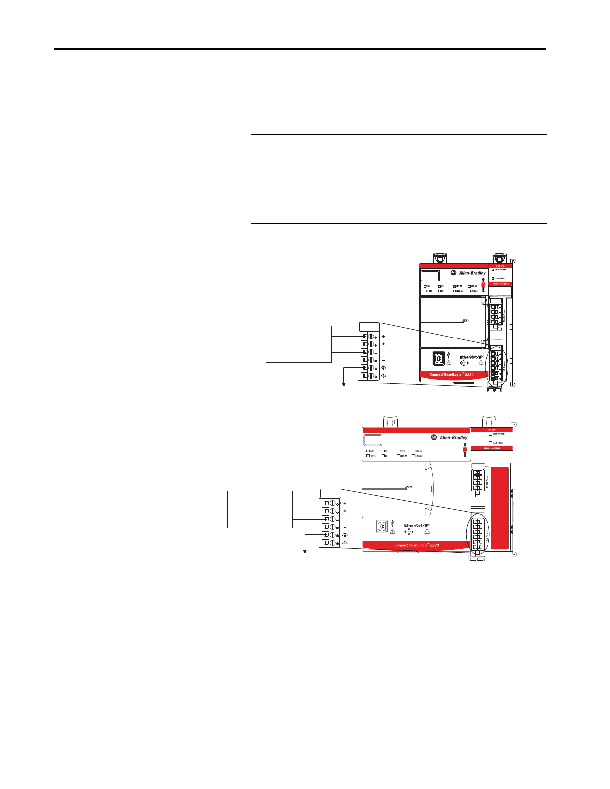
Chapter 3 How to Power Compact GuardLogix 5380 Controllers
24V DC
SELV/PELV-listed
power supply
+
–
24V DC
SELV/PELV-listed
power supply
+
–
Figure 13 - External Power Supply Provides SA Power
• Connections to an SA power bus use a shared common. All inputs that
draw current from an SA power bus to power field-side devices have a
return through circuitry to the SA - terminal on the SA power
connector.
IMPORTANT Each SA power bus has a shared common unique to that bus
because SA power buses are completely isolated from each other.
That is, the SA power bus that the controller establishes has a
shared common. If you use a 5069-FPD field potential distributor to
establish a new SA power bus in the system, that second bus has its
own shared common for modules that draw current from it.
42 Rockwell Automation Publication 5069-UM001G-EN-P - August 2020
Page 43

How to Power Compact GuardLogix 5380 Controllers Chapter 3
When the SA power source is turned on, the following occurs.
1. The controller draws current from the SA power bus and passes the
remaining current through to the next module.
IMPORTANT The level of current that the Compact GuardLogix 5380 controller
draws from the SA power bus is negligible. It draws 10 mA.
2. The next module completes one of these tasks.
– If the module uses SA power, the module draws current from the SA
power bus and passes the remaining current through to the next
module.
– If the module does not use SA power bus current, the module passes
the remaining current through to the next module.
3. The process continues until all SA power bus current needs are met for
the modules on the SA power bus.
For more information on the current that the Compact 5000 I/O modules
draw from the SA power bus, see the Compact 5000 I/O Modules and
EtherNet/IP Adapters Technical Data, publication 5069-TD001
.
Rockwell Automation Publication 5069-UM001G-EN-P - August 2020 43
Page 44

Chapter 3 How to Power Compact GuardLogix 5380 Controllers
Continuous MOD Power Bus Limited to 5 A, Max
Continuous SA Power Bus Limited to 10 A, Max
SA Power Bus Current, Max,
Per Module
10 mA
System SA Power Bus Current, Max = 1.27 A
80 mA 80 mA 0 mA
0 mA
900 mA 0 mA 100 mA 100 mA 0 mA 0 mA
Track SA Power Bus Current Draw
We recommend that you track the SA power bus current draw, max, per
module, and collectively for the Compact GuardLogix 5380 system. You must
make sure that the Compact 5000 I/O modules that are installed on an SA
power bus do not consume more than 10 A. If so, you must establish another
SA power bus.
Consider the following with this example:
• The values in this example represent a worst-case calculation. That is, all
modules that draw SA power bus current, draw the maximum available
on the module.
• Not all modules that are shown in Figure 14 on page 44
use SA power
bus current. For example, the 5069-OBV8S, 5069-ARM and
5069-OB16 modules only pass SA power bus current to the next
module. Other modules that do not use SA power bus current, but are
not shown in the graphic, include the 5069-OB16F and 5069-OX4I
modules.
• System SA power bus current, max, is calculated as each module draws
SA power bus current. The calculation begins with the controller. The
controller SA power bus current draw used for the calculation is
10 mA for DC power
In Figure 14
, after the 5069-IB8S module in slot 1 draws SA power bus
current, the system SA power bus current, max, is 90 mA.
After the 5069-IB8S module in slot 2 draws SA power bus current, the
system SA power bus current draw is 170 mA. This process continues
until the system SA power bus current, max, is 1.27 A.
Figure 14 - Compact GuardLogix 5380 System - Calculate SA Power Bus Current Draw
(1)
44 Rockwell Automation Publication 5069-UM001G-EN-P - August 2020
(1) Although a Compact GuardLogix 5380 SIL2 controller is shown, this example also applies to Compact GuardLogix 5380 SIL 3
controllers.
Page 45
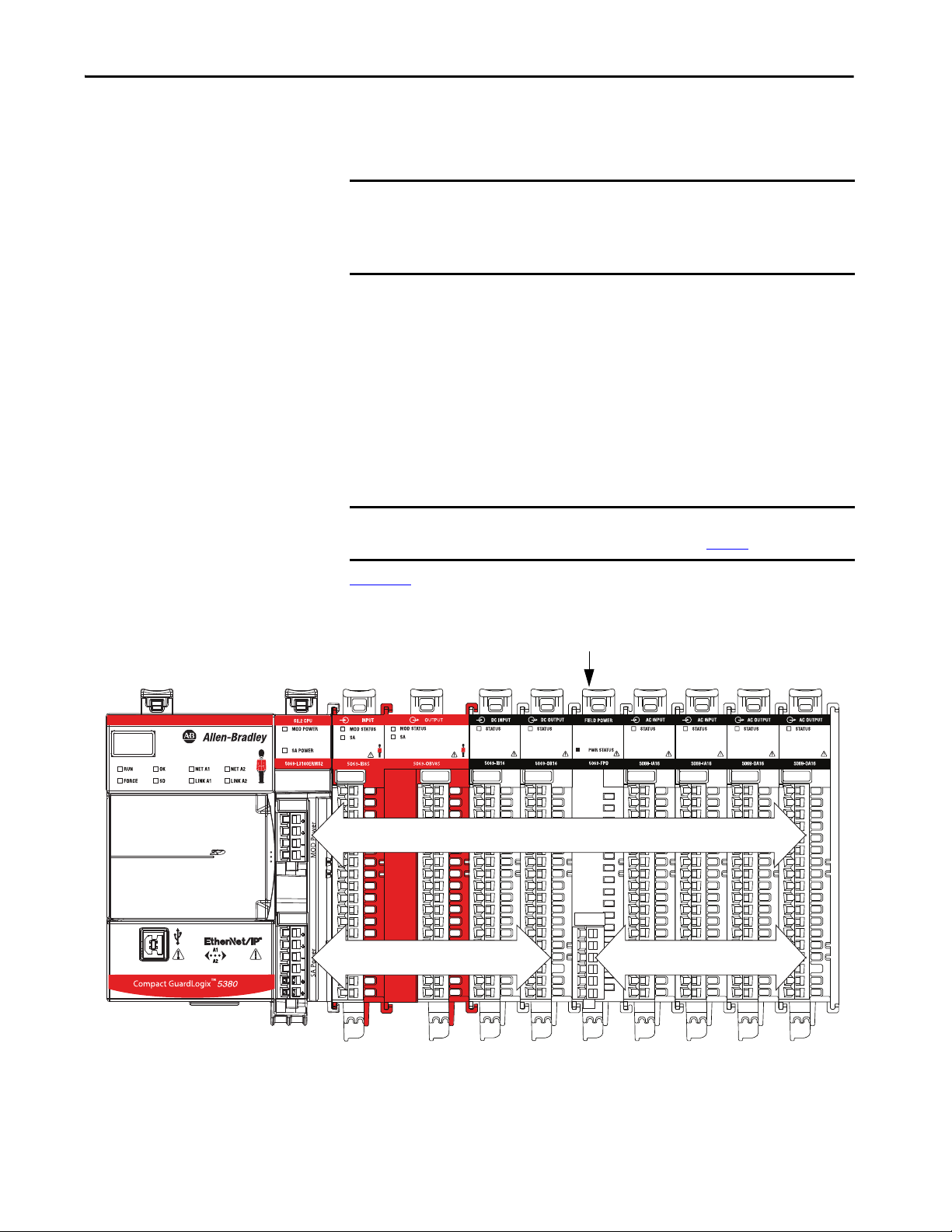
How to Power Compact GuardLogix 5380 Controllers Chapter 3
MOD Power Bus
First SA Power Bus Second SA Power Bus
5069-FPD Field Potential Distributor
Use a 5069-FPD Field Potential Distributor to Create a New SA Power Bus
IMPORTANT If you use local Compact 5000 I/O relay modules, or an AC voltage for local
Compact 5000 I/O modules, then you must connect through a 5069-FPD
field potential distributor module. An AC voltage cannot be terminated on
the controller.
You can use a 5069-FPD field potential distributor to establish a new SA power
bus in a Compact GuardLogix 5380 system.
The field potential distributor blocks the current that passes across the SA
power bus to its left. At that point, the field potential distributor establishes a
new SA power bus for modules to the right. The new SA power bus is isolated
from the SA power bus to its left in the system.
You can connect either a 24V DC or 120/240V AC external power supply to a
5069-FPD field potential distributor in a Compact GuardLogix 5380 system.
IMPORTANT Some restrictions apply when you connect SA power to a 5069-FPD field
Figure 15
potential distributor. For more information, see page 46
shows a Compact GuardLogix 5380 system that uses a 5069-FPD
.
field potential distributor to create a second SA power bus.
Figure 15 - Compact GuardLogix 5380 System - Create a New SA Power Bus
(1)
You can install multiple 5069-FPD field potential distributors in the same
system, if necessary.
(1) Although a Compact GuardLogix 5380 SIL2 controller is shown, this example also applies to Compact GuardLogix 5380 SIL 3
Rockwell Automation Publication 5069-UM001G-EN-P - August 2020 45
controllers.
Page 46
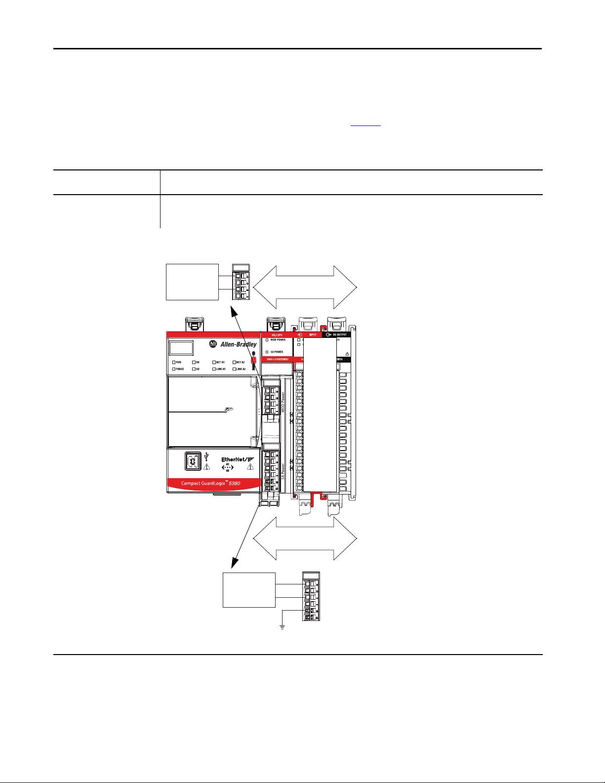
Chapter 3 How to Power Compact GuardLogix 5380 Controllers
MOD Power - from
SELV-listed Power Supply
SA Power Bus - From
SELV-listed Power Supply
24V DC
SELV-listed
Power Suppl y
+
–
24V DC
SELV-listed
Power Supply
+
–
Compact 5000 I/O 24V DC safety and
standard input module
Ground
*Although a Compact GuardLogix 5380 SIL2
controller is shown, this example also applies to
Compact GuardLogix 5380 SIL 3 controllers.
Restrictions When You Connect SA Power to a Compact GuardLogix 5380 System
Remember these restrictions in Ta b l e 2 when you connect SA power to a
Compact GuardLogix 5380 system.
Table 2 - SA Power Restrictions - Compact GuardLogix 5380 System
Component to Which SA Power
Is Connected
Compact GuardLogix 5380 SIL 2 or
SIL 3 Controller
Restric tions
• You must use SELV/PELV-listed power supplies to provide SA power to Compact GuardLogix 5380 controllers.
• You can only connect a 24V DC SELV/PELV-listed power supply.
• The total continuous current draw across the SA power bus must not be more than 10 A, max at 0…32V DC.
Example Compact GuardLogix System
46 Rockwell Automation Publication 5069-UM001G-EN-P - August 2020
Page 47
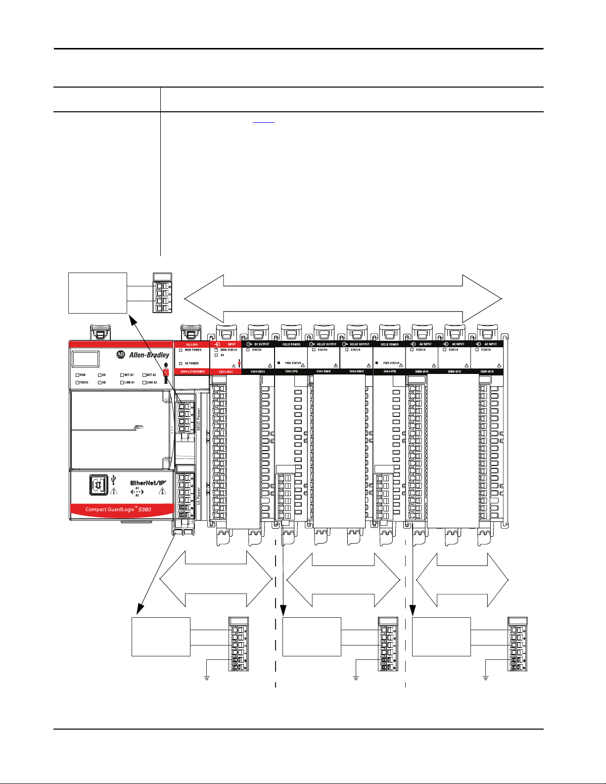
Table 2 - SA Power Restrictions - Compact GuardLogix 5380 System
MOD Power - from SELV-listed Power Supply
SA Power Bus - From
SELV-listed Power Supply
24V DC
SELV-listed
Power Supply
+
–
24V DC
SELV-listed
Power Supply
+
–
Compact 5000 I/O 24V DC safety and
standard input module
Ground
SA Power Bus - From
Standard Power Supply
120/240V AC
Standard Power
Supply
+
–
Ground
Compact 5000 I/O 120/240V AC
standard input modules
Compact 5000 I/O 24V D C relay modules
24V DC Standard
or SELV-listed
Power Supply
+
–
Ground
SA Power Bus - From
Standard or SELV-listed
Power Supply
*Although a Compact GuardLogix 5380 SIL2 controller is shown, this
example also applies to Compact GuardLogix 5380 SIL 3 controllers.
How to Power Compact GuardLogix 5380 Controllers Chapter 3
Component to Which SA Power
Is Connected
5069-FPD Field Potential Distributor
With Compact 5000 I/O Standard
Modules Only
Restric tions
In addition to the restrictions on page 46, these restrictions also apply:
• You can use non-SELV or PELV power supplies if only Compact 5000 I/O standard modules are installed to the right of the 5069-FPD field
potential distributor.
• You can connect a 24V DC or 120/240V AC power supply. The example uses a 120/240V AC power supply.
– If the SA power that is connected to the 5069-FPD field potential distributor is DC voltage, the total continuous current draw across
the SA power bus must not be more than 10 A, max at 0…32V DC.
– If a Compact GuardLogix 5380 system includes Compact 5000 I/O relay modules (5069-OW4I, 5069-OX4I, 5069-OW16), or
I/O modules that require SA power that is AC voltag e, you must install these modules to the right of a 5069-FPD field potential
distributor, as shown.
IMPORTANT: This requirement applies even if it means that you must install the 5069-FPD field potential distributor immediately to
the right of the Compact GuardLogix 5380 controller.
• If a Compact GuardLogix 5380 system includes Compact 5000 I/O standard modules that use SA power that is provided by a power
supply that is not SELV/PELV-listed, the I/O modules must be installed to the right of a 5069-FPD field potential distributor.
IMPORTANT: The SA power bus that the 5069-FPD field potential distributor establishes cannot include any Compact 5000 I/O safety
modules.
Example Compact GuardLogix System
Rockwell Automation Publication 5069-UM001G-EN-P - August 2020 47
Page 48
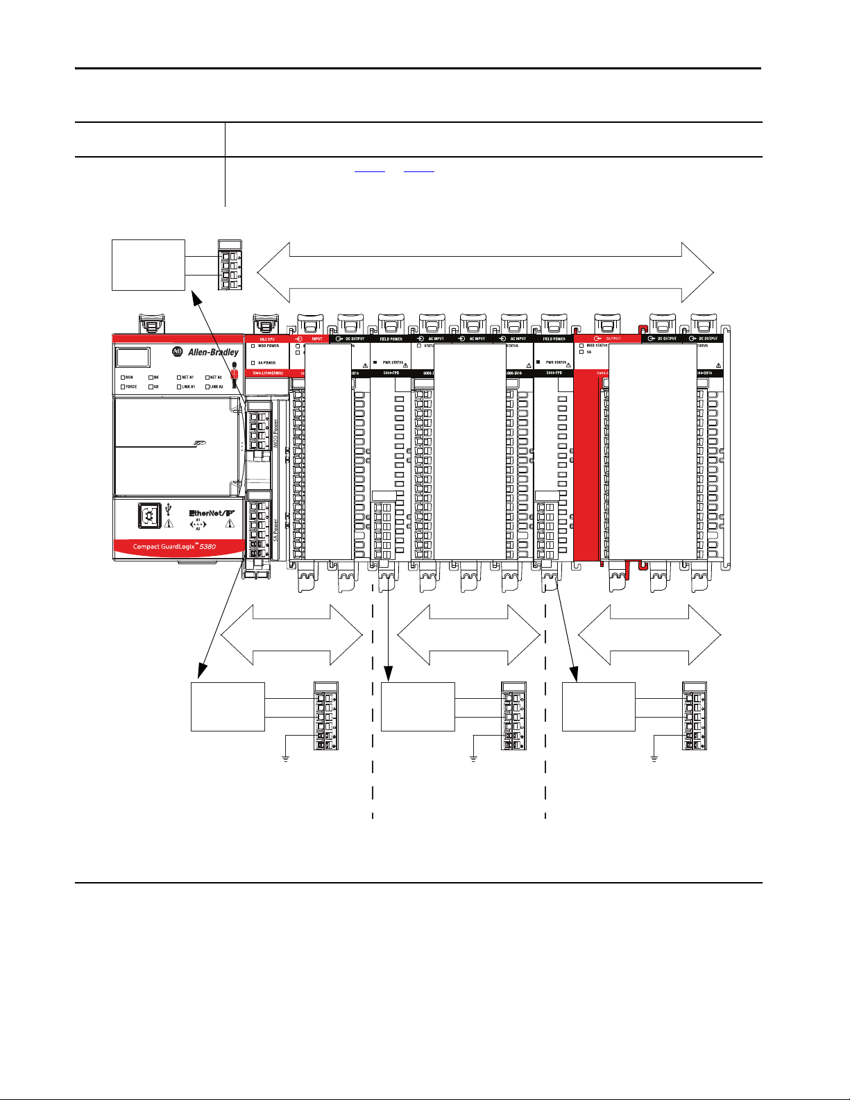
Chapter 3 How to Power Compact GuardLogix 5380 Controllers
MOD Power - from SELV-listed Power Supply
SA Power Bus - From
SELV-listed Power Supply
24V DC
SELV-listed
Power Supply
+
–
24V DC
SELV-listed
Power Supply
+
–
Compact 5000 I/O 24V DC safety and
standard input module
Ground
SA Power Bus - From
Standard Power Supply
120/240V AC
Standard Power
Supply
+
–
Ground
Compact 5000 I/O 120/240V AC
standard input module
SA Power Bus - From
SELV-listed Power Supply
24V DC
SELV-listed
Power Supply
+
–
Ground
Compact 5000 I/O 24V DC safety and
standard output module
*Although a Compact GuardLogix 5380 SIL2 controller is shown, this
example also applies to Compact GuardLogix 5380 SIL 3 controllers.
Table 2 - SA Power Restrictions - Compact GuardLogix 5380 System
Component to Which SA Power
Is Connected
5069-FPD Field Potential Distributor
With Compact 5000 I/O Safety and
Standard Modules
Restric tions
In addition to the restrictions on page 46 and page 47, this restriction also applies:
• You must use SELV or PELV power supplies to provide SA power to Compact 5000 I/O safety modules that are installed to the right of the
5069-FPD field potential distributor.
Example Compact GuardLogix 5380 System
48 Rockwell Automation Publication 5069-UM001G-EN-P - August 2020
Page 49

How to Power Compact GuardLogix 5380 Controllers Chapter 3
SA Power - Additional Notes
• Other examples of system configurations that use multiple SA power
buses include:
– The modules in the system collectively draw more than 10 A of SA
power. That is, the maximum current that one SA power bus
can provide.
– The modules in the system must be isolated according to module
types, such as digital I/O and analog I/O modules.
– The modules in the system are isolated according to the type of
field-side device to which they are connected.
For example, you can separate modules that are connected to fieldside devices that use DC voltage from modules that are connected to
field-side devices that require AC voltage.
• The actual current in a Compact GuardLogix 5380 system changes
based on the operating conditions at a given time.
For example, the SA power bus current draw on some modules is
different if all channels power field devices or half of the channels power
field devices.
• Some Compact 5000 I/O modules use field-side power but do not draw
it from a SA power bus. The modules receive field-side power from an
external power supply that is connected directly to the I/O module.
For example, the 5069-OB16, 5069-OB16F, and 5069-OBV8S
modules use Local Actuator (LA) terminals on the module RTB, that is,
LA+ and LA– terminals for all module channels.
In this case, you can use the same external power supply that is
connected to the SA power RTB on the controller to the LA+ and LA–
terminals.
IMPORTANT You must consider the current limit of an external power supply if
you use it to provide power to the SA power RTB on the controller
and the LA+ and LA– terminals on a 5069-OB16, 5069-OB16F, or
5069-OBV8S module. The 5069-OBV8S module requires a
SELV/PELV-rated power supply.
Rockwell Automation Publication 5069-UM001G-EN-P - August 2020 49
Page 50

Chapter 3 How to Power Compact GuardLogix 5380 Controllers
Notes:
50 Rockwell Automation Publication 5069-UM001G-EN-P - August 2020
Page 51

Chapter 4
Safety Concept of Compact GuardLogix 5380
Controllers
Top ic Pag e
Functional Safety Capability 51
Safety Network Number 52
Safety Signature 53
Distinguish Between Standard and Safet y Components 53
Controller Data-flow Capabilities 54
Safety Terminology 55
Functional Safety Capability
Applies to these controllers:
Compact GuardLogix 5380 SIL 2
Compact GuardLogix 5380 SIL 3
The Compact GuardLogix® 5380 controller systems are certified for use in
safety applications up to and including SIL 2/PLd and SIL 3/PLe where the
de-energized state is the safe state.
Controller System IEC 61508 IEC 62061 ISO 13849-1
Type-approved and
certified for use in
safety applications
up to and including:
Compact GuardLogix 5380
SIL 2 controller systems
Compact GuardLogix 5380
SIL 3 controller systems
(1) Compact GuardLogix 5380 SIL 2 controller catalog numbers have a ‘2’ at the end, for example, 5069-L3xxxxxS2, and are for use
in safety applications up to and including SIL 2.
(2) Compact GuardLogix 5380 SIL 3 controller catalog numbers have a ‘3’ at the end, for example, 5069-L3xxxxxS3, and are for use
in safety applications up to and including SIL 3.
(3) For SIL 3/PLe safety applications, the Compact GuardLogix® 5380 SIL 3 co ntroller system consi sts of a primar y controller with an
internal safety partner, that function together in a 1oo2 architecture.
SIL 2 SIL CL2 Performance Level PLd (Cat. 3)
(1)
SIL 3 SIL CL3 Performance Level PLe (Cat. 4)
(2)(3)
Suitable for use in
safety applications up
to and including:
Suitable for use in safety
applications up to and including:
Compact GuardLogix 5380 controller-based safety applications require a
safety signature be used.
For SIL 2/PLd and SIL 3/PLe safety system requirements, including
functional validation test intervals, system reaction time, and
PFD/PFH calculations, see to the GuardLogix 5580 and Compact
GuardLogix 5380 Controller Systems Safety Reference Manual, publication
1756-RM012
.
You must read, understand, and fulfill these requirements before you operate a
Compact GuardLogix safety system.
Rockwell Automation Publication 5069-UM001G-EN-P - August 2020 51
Page 52
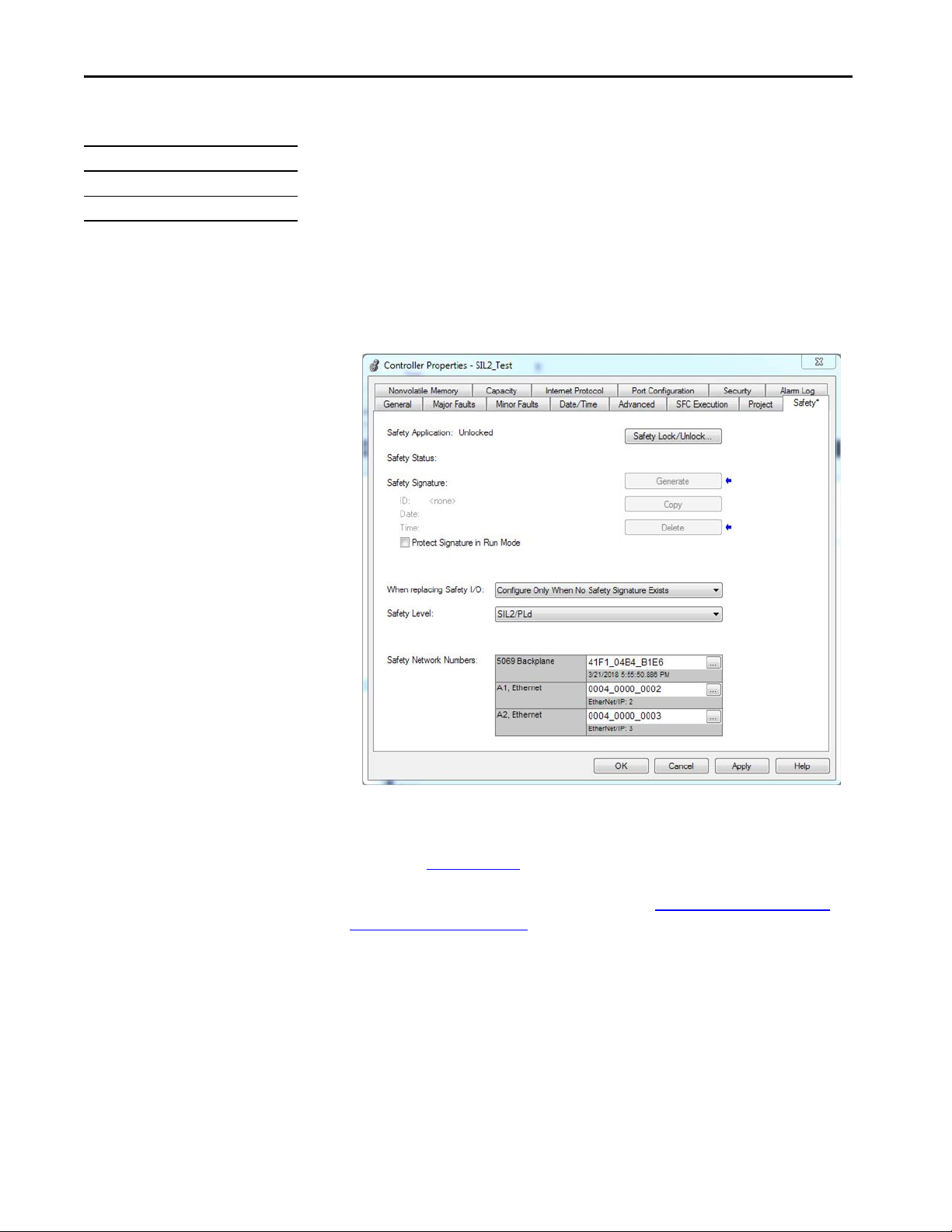
Chapter 4 Safety Concept of Compact GuardLogix 5380 Controllers
Safety Network Number
Applies to these controllers:
Compact GuardLogix 5380 SIL 2
Compact GuardLogix 5380 SIL 3
The safety network number (SNN) uniquely identifies CIP Safety™ subnets
within a routable safety network. The combination of SNN + Node Address
uniquely identifies each CIP Safety port on each device in the routable safety
network.
The application assigns an SNN to each CIP Safety subnet attached to a
Compact GuardLogix 5380 controller, including the backplane. If there are
other Logix Safety controllers on an attached Ethernet network, assign the
same SNN for this network in each controller application. This allows you to
use Logix Designer's automatic assignment of safety network numbers for
devices added to the application.
For an explanation of the Safety Network Number, see the GuardLogix 5580
and Compact GuardLogix 5380 Controller Systems Safety Reference Manual,
publication 1756-RM012.
For information on how to assign the SNN, see Assign the Safety Network
Number (SNN) on page 78.
52 Rockwell Automation Publication 5069-UM001G-EN-P - August 2020
Page 53

Safety Concept of Compact GuardLogix 5380 Controllers Chapter 4
Safety Signature
Applies to these controllers:
Compact GuardLogix 5380 SIL 2
Compact GuardLogix 5380 SIL 3
Distinguish Between Standard and Safety Components
Applies to these controllers:
Compact GuardLogix 5380 SIL 2
Compact GuardLogix 5380 SIL 3
The safety signature is composed of a safety signature ID (identification
number), and a timestamp (date and time). The safety signature ID applies to
the entire safety portion of the controller and uniquely identifies each project,
including its logic, data, and configuration.
The Compact GuardLogix 5380 system uses the safety signature to determine
project integrity and to let you verify that the correct project is downloaded to
the target controller. The ability to create, record, and verify that the safety
signature is a mandatory part of the safety-application development process.
The safety signature must be present to operate as a SIL 2/PLd or SIL 3/PLe
safety controller.
See Generate the Safety Signature on page 254
Slots of a Compact GuardLogix 5380 system chassis that are not used by the
safety function can be populated with other Compact 5000™ I/O modules that
are certified to the Low Voltage and EMC Directives. See
www.rockwellautomation.com/rockwellautomation/certification/ce.page
find the CE certificate for the CompactLogix™ Product Family and determine
the modules that are certified.
You must create and document a clear, logical, and visible distinction between
the safety and standard portions of the controller project. As part of this
distinction, the Studio 5000 Logix Designer® application features safety
identification icons to identify the safety task, safety programs, safety routines,
and safety components.
for more information.
http://
to
In addition, the Logix Designer application displays a safety class attribute
whenever safety task, safety programs, safety routine, safety tag, or safety
Add-On Instruction properties are displayed.
Rockwell Automation Publication 5069-UM001G-EN-P - August 2020 53
Page 54
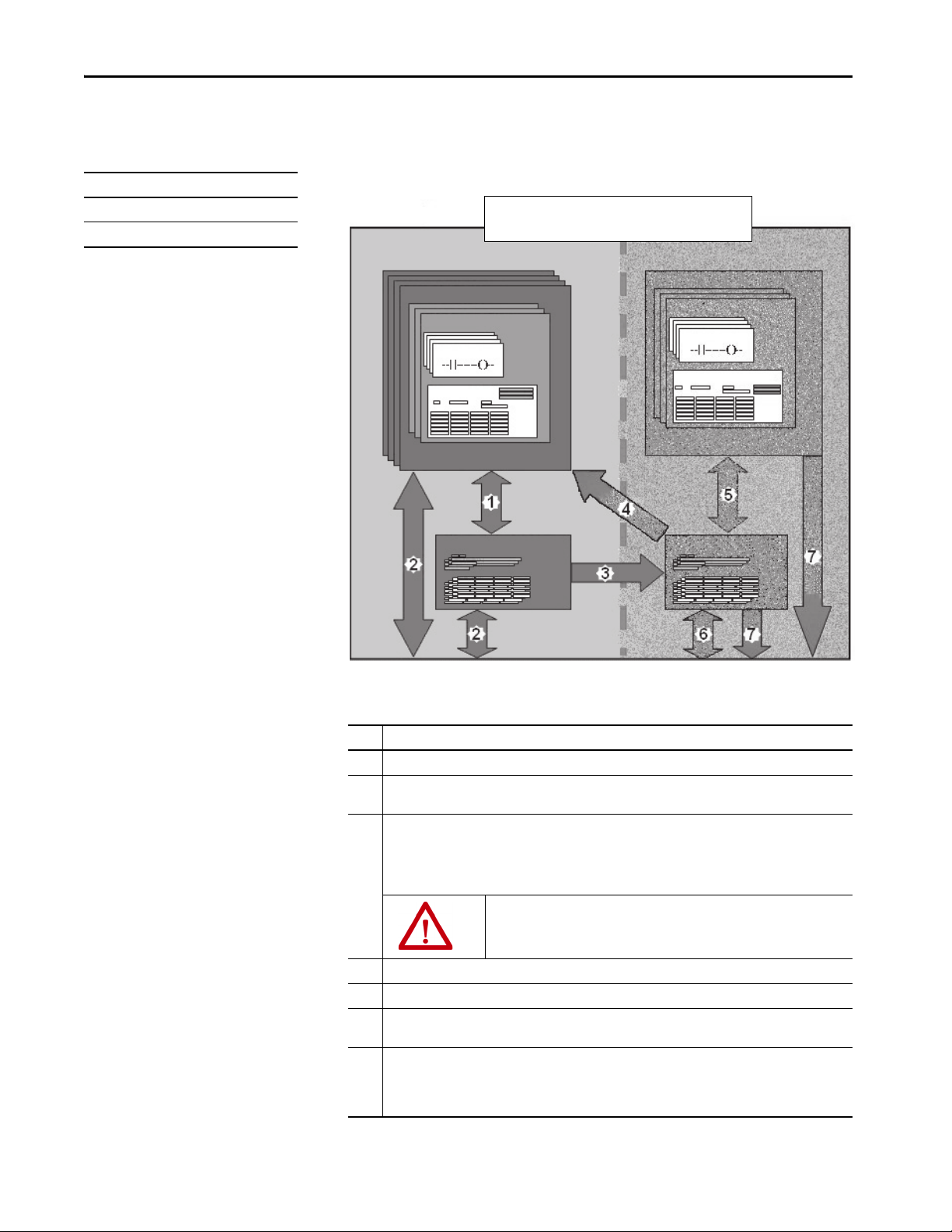
Chapter 4 Safety Concept of Compact GuardLogix 5380 Controllers
Standard Safety
Standard Tasks
Safety Task
Safety Programs
Standard Programs
Standard Routines
Program Data
Program Safety Data
Safety Routines
Controller Standard Tags
Controller Safety Tags
Compact GuardLogix 5380 Controllers
Controller Data-flow Capabilities
Applies to these controllers:
Compact GuardLogix 5380 SIL 2
Compact GuardLogix 5380 SIL 3
This illustration explains the standard and safety data-flow capabilities of the
Compact GuardLogix 5380 controllers.
Figure 16 - Data-flow Capabilities
No. Description
1 Standard tags and logic behave the same way that they do in a standard CompactLogix 5380 controller.
54 Rockwell Automation Publication 5069-UM001G-EN-P - August 2020
2 Standard tag data, program- or controller-scoped, can be exchanged with external HMI devices, personal
computers, and other controllers.
3 Compact GuardLogix 5380 controllers are inte grated controllers with the abili ty to move (map) standard tag
data into safety tags for use within the safety task. This is the only way to get standard tag data in to the
safety task. Safety logic in the safety task cannot read or write the standard tag that is the source in the tag
mapping data transfer; it can only reference the safety tag destination of the mapping. But, it can read and
write that safety tag.
ATT EN TI ON : Mapped tag data must not be used to control a SIL 2/PLd or
SIL 3/PLe output directly.
4 Controller-scoped safety tags can be read direc tly by stand ard logic.
5 Safety tags can be read or written by safety logic.
6 Safety tags can be exchanged between safety controllers over Ethernet networks, including
1756 GuardLogix controllers and 5069 Compact GuardLogix controllers.
7 Safety tag data, program- or controller-scoped, can be read by external devices, such as HMI devices,
personal computers, or other standard controllers. External devices cannot write to safety tags (whether the
controller is protected or not).
Once this data is read, it is considered standard data, not safety data.
Page 55

Safety Concept of Compact GuardLogix 5380 Controllers Chapter 4
Safety Terminology
Abbreviation Full Term Definition
1oo1 One Out of One Identifies the programmable electronic controller architecture. 1oo1 is a single -channel system.
1oo2 One Out of Two Identifies the programmable electronic controller architecture. 1oo2 is a dual-channel system.
CIP Safety Common Industrial Protocol – Safety
DC Diagnostic Coverage The ratio of the detected failure rate to the total failure rate.
PFD Probability of a dangerous failure on
PFH Probability of dangerous failure per hour The average frequency of a dangerous failure per hour.
PL Performance Level ISO 13849-1 safety rating.
SIL Safety Integrity Level A relative level of risk-reduction that is provided by a safety function, or to specify a target level of risk reduction.
SIL CL SIL Claim Limit The maximum safety integrity level (SIL) that can be achieved.
SNN Safety Network Number A unique number that identifies a sec tion of a safety network.
UNID
Cert ified
demand
Unique Node ID (also called unique node
referenc e)
The following table defines terms that are used in this manual.
SIL 3/PLe-rated version of CIP™.
The average probability of a dangerous failure on demand.
The unique node reference is a combination of a safety network number (SNN) and the node address of the node.
Rockwell Automation Publication 5069-UM001G-EN-P - August 2020 55
Page 56

Chapter 4 Safety Concept of Compact GuardLogix 5380 Controllers
Notes:
56 Rockwell Automation Publication 5069-UM001G-EN-P - August 2020
Page 57

Connect to the Controller
Top ic Pag e
Before You Begin 57
Connection Options 58
Set the IP Address 59
Update Controller Firmware 63
Controllers with Firmware Earlier than Rev ision 31 73
Chapter 5
Before You Begin
Applies to these controllers:
CompactLogix™ 5380
Compact GuardLogix® 5380 SIL 2
Compact GuardLogix 5380 SIL 3
Before you can connect to the controller through the EtherNet or USB port,
you must configure the EtherNet/IP™ or USB driver in Linx-based software on
your workstation.
• The controller has an Ethernet port that supports 10 Mbps, 100 Mbps,
or 1 Gbps
• The controller has a USB port that uses a Type B receptacle. The port is
USB 2.0 compatible and runs at 12 Mbps.
• Install and configure a communication module in the chassis with the
controller as described in the installation instructions for the
communication module.
The EtherNet/IP driver:
– Supports runtime communications
– Requires that the workstation and the controller are configured
– Supports communications over longer distances when compared to
the USB driver
USB driver:
– Convenient method to connect to an unconfigured controller and
configure the Ethernet port
– Convenient method to connect to a controller when the Ethernet
port configuration is unknown
– Convenient method to update the controller firmware
– Not intended for runtime connections; it is a temporary-use only
connection with a limited cabling distance
For information on how to configure EtherNet/IP or USB drivers, see the
EtherNet/IP Network Devices User Manual, publication ENET-UM006
Rockwell Automation Publication 5069-UM001G-EN-P - August 2020 57
.
Page 58

Chapter 5 Connect to the Controller
Port A1
Port A2
Connection Options
Applies to these controllers:
CompactLogix 5380
Compact GuardLogix 5380 SIL 2
Compact GuardLogix 5380 SIL 3
Before you can begin using your controller, you must make a connection to the
controller. Make sure that you have already configured the EtherNet/IP or
USB communication drivers (see the EtherNet/IP Network Devices User
Manual, publication ENET-UM006
).
Connection options with the controller include:
• Ethernet cable to an Ethernet port - The controller Ethernet ports
support communication rates of 10 Mbps, 100 Mbps, and 1 Gbps. See
Connect an Ethernet Cable on page 58
.
• USB cable to the USB port - The controller USB port uses a Type B
receptacle and is USB 2.0 compatible. The port runs at 12 Mbps. See
Connect a USB Cable on page 59
.
Connect an Ethernet Cable
The example graphic shows a Compact GuardLogix 5380 controller. You
perform the same task to connect an Ethernet cable to a CompactLogix 5380
controller.
WARNING: If you connect or disconnect the communications cable with
power applied to this module or any device on the network, an electric arc
can occur. This could cause an explosion in hazardous location installations.
Be sure that power is removed or the area is nonhazardous before
proceeding.
If you are connecting a controller directly to an EtherNet/IP network, connect
a CAT 5e or CAT 6 Ethernet cable with an RJ45 connector to an Ethernet
port on the bottom of the controller.
For information on how to select the proper cable, see Guidance for Selecting
Cables for EtherNet/IP Networks, publication ENET-WP007-EN-P
.
58 Rockwell Automation Publication 5069-UM001G-EN-P - August 2020
Page 59

Connec t to the Controller Chapter 5
Connect a USB Cable
Use the USB connection to update firmware and download programs.
The example graphic shows a CompactLogix 5380 controller. You perform the
same task to connect an Ethernet cable to a Compact GuardLogix 5380
controller.
The USB port is intended only for temporary local programming purposes and
not intended for permanent connection. The USB cable is not to exceed 3.0 m
(9.84 ft) and must not contain hubs.
WARNING: Do not use the USB port in hazardous locations.
Figure 17 - USB Connection
Set the IP Address
Applies to these controllers:
CompactLogix 5380
Compact GuardLogix 5380 SIL 2
Compact GuardLogix 5380 SIL 3
When the controller is in the out-of-the-box condition, the following apply
regarding IP addresses:
• The controller embedded Ethernet ports are configured to obtain an IP
address via a DHCP server.
If there is no DHCP server or the DHCP server is not configured to set
the IP address, you must set the IP address manually.
• The controller is configured so that you must set the IP address each
time that power is cycled.
You can configure your controller so that you are not required to set an
IP address each time that power is cycled.
• The controller is configured to use Dual-IP mode. As a result, you must
set a unique IP address for port A1 and port A2.
Rockwell Automation Publication 5069-UM001G-EN-P - August 2020 59
Page 60

Chapter 5 Connect to the Controller
Requirements
To set the IP address, have the following:
• EtherNet/IP or USB drivers installed on the programming workstation
• MAC ID from the device, which is on the label on the side of the device
• Recommended IP address for the device
Other Methods to Set the IP Address
The controller supports the following methods to change the IP address:
• BOOTP/DHCP utility
• RSLinx® Classic software
• Studio 5000 Logix Designer® application
For more information on how to use these methods, see EtherNet/IP Network
Devices User Manual, publication ENET-UM006
.
Duplicate IP Address Detection
IMPORTANT The EtherNet/IP mode in which the controller operates affects the setting
and use of IP addresses on the controller. For example, if the controller
operates in Dual-IP mode, you must set an IP address for each controller
Ethernet port. That is, you must complete the steps that are described in this
section twice–once for each port.
For more information on how the EtherNet/IP modes affect the controller IP
address, see Use EtherNet/IP Modes on page 135
.
Use a Secure Digital Card to Set the Controller IP Address
You can use an SD card to set the controller IP address. The SD card can set the
IP address when it loads a project onto the controller.
For more information on how to use an SD card, see Use the Secure Digital
Card on page 107.
The controller verifies that its IP address does not match any other network
device IP address when you perform either of these tasks:
Applies to these controllers:
CompactLogix 5380
Compact GuardLogix 5380 SIL 2
Compact GuardLogix 5380 SIL 3
60 Rockwell Automation Publication 5069-UM001G-EN-P - August 2020
• Connect the controller to a EtherNet/IP network.
• Change the controller IP address.
If the controller IP address matches that of another device on the network, the
controller Ethernet port transitions to Conflict mode. In Conflict mode, these
conditions exist:
Page 61
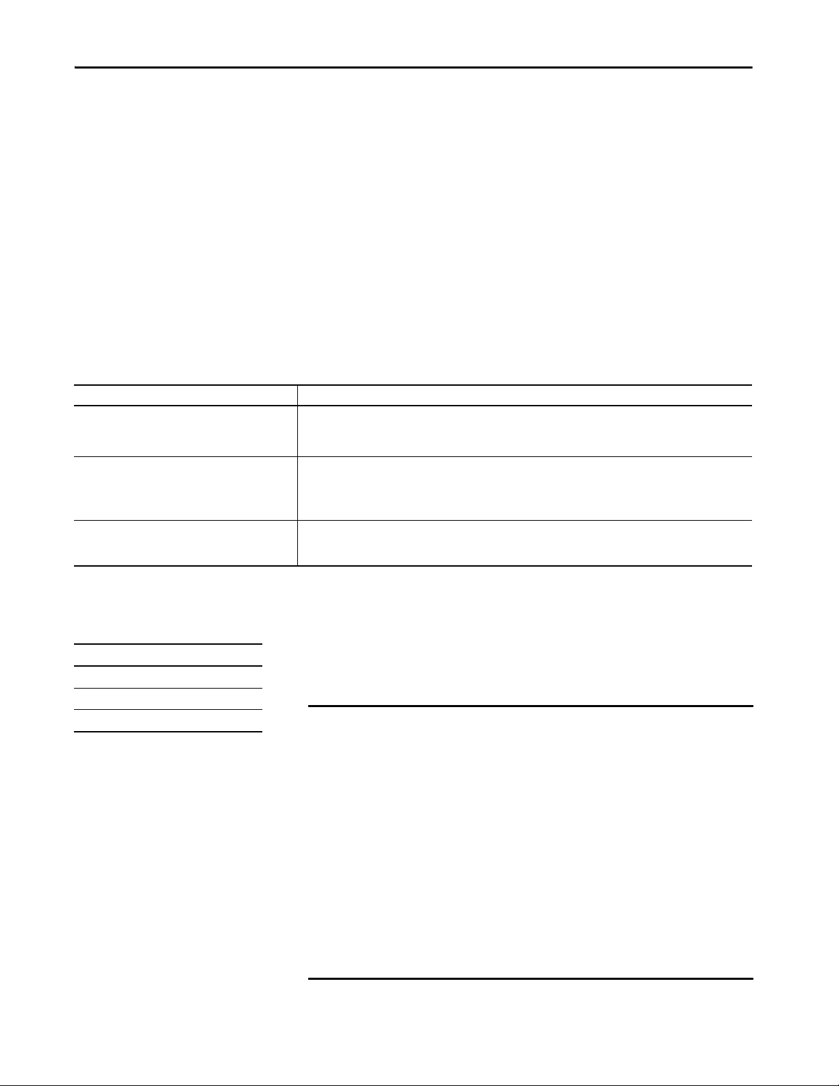
• Network (NET) status indicator is solid red.
• The 4-character display indicates the conflict.
The display scrolls: <IP_address_of_this_module> Duplicate IP
<Mac_address_of_duplicate_node_detected>
For example: 192.168.1.1 Duplicate IP - 00:00:BC:02:34:B4
Duplicate IP Address Resolution
When two devices on a network have IP addresses that conflict, the resolution
depends on the conditions in which the duplication is detected. This table
describes how duplicate IP addresses are resolved.
Duplicate IP Address Detection Conditions Resolution Process
• Both devices support duplicate IP address detection.
• Second device is added to the network after the first
device is operating on the network.
• Both devices support duplicate IP address detection.
• Both devices were powered up at approximately the
same time.
One device supports duplicate IP address detection and a
second device does not.
1. The device that began operation first uses the IP address and continues to operate without interruption.
2. The device that begins operation second detects the duplication and enters Conflict mode.
Both EtherNet/IP devices enter Conflict mode.
To resolve this conflict, follow these steps:
a. Assign a new IP address to the controller.
b. Cycle power to the other device.
1. Regardless of which device obtained the IP address first, the device that does not support IP address detection uses
the IP address and continues to operate without interruption.
2. The device that supports duplicate IP address detection detects the duplication and enters Conflict mode.
Connec t to the Controller Chapter 5
DNS Addressing
Applies to these controllers:
CompactLogix 5380
Compact GuardLogix 5380 SIL 2
Compact GuardLogix 5380 SIL 3
You can also use DNS addressing to specify a host name for a controller, a
domain name, and DNS servers. DNS addressing makes it possible to
configure similar network structures and IP address sequences under different
domains.
IMPORTANT Safety Considerations
• Safety connections are not allowed to use host names (this requires DNS
lookup, which is not allowed for Safety I/O). Safety devices on EtherNet/
IP networks do not present the host name parameter. Standard devices
do present the host name parameter, regardless of whether the project is
safety or standard.
• Compact GuardLogix 5380 controllers can have safety connections or
standard connections. When used in a standard project, GuardLogix
5580 controllers are considered standard devices (the only connections
are standard consumed tags), so the controller presents the host name
parameter.
• When Compact GuardLogix 5380 controllers are used in a safety project,
it is assumed to be a safety device, and the host name parameter is not
presented.
Rockwell Automation Publication 5069-UM001G-EN-P - August 2020 61
Page 62

Chapter 5 Connect to the Controller
DNS addressing is necessary only if you refer to the controller by host name,
such as in path descriptions in MSG instructions.
To use DNS addressing, follow these steps.
1. Assign a host name to the controller.
A network administrator can assign a host name. Valid host names must
be IEC-1131-3 compliant.
2. Configure the controller parameters.
3. Configure the IP address, subnet mask, gateway address, a host name for
the controller, domain name, and primary/secondary DNS server
addresses.
In the DNS server, the host name must match the IP address of the
controller.
4. In the Logix Designer application, add the controller to the I/O
configuration tree.
IMPORTANT Remember the following:
• If a child module resides in the same domain as its parent module, type
the host name. If the domain of the child module differs from the domain
of its parent module, type the host name and the domain name
(hostname.domainname)
• You can also use DNS addressing in a module profile in the I/O
configuration tree or in a message path. If the domain name of the
destination module differs from the domain name of the source module,
then use a fully qualified DNS name (hostname.domainname). For
example, to send a message from EN2T1.location1.companyA to
EN2T1.location2.companyA, the host names match, but the domains
differ. Without the entry of a fully qualified DNS name, the module adds
the default domain name to the specified host name.
62 Rockwell Automation Publication 5069-UM001G-EN-P - August 2020
Page 63

Connec t to the Controller Chapter 5
Update Controller Firmware
Applies to these controllers:
CompactLogix 5380
Compact GuardLogix 5380 SIL 2
Compact GuardLogix 5380 SIL 3
You can use these tools to update the controller firmware:
• ControlFLASH™ or ControlFLASH Plus™ software
• AutoFlash feature of the Logix Designer application
Firmware Upgrade Guidelines for Safety Controllers
IMPORTANT Safety Consideration
You cannot update a controller that is safety locked.
The IEC 61508 functional safety standard requires impact analysis before
upgrading or modifying components in a certified, functional safety system.
This section provides high-level guidance on how you can perform the impact
analysis for safety controller hardware/firmware upgrades. Reference the
standard to make sure you fulfill all of the requirements as they relate to your
application.
When you upgrade controller firmware to a newer version, consider the
following:
• All major and minor firmware releases for Compact GuardLogix
controller systems are certified for use in safety applications. As part of
the certification process, Rockwell Automation tests the safety-related
firmware functions (for example the CIP Safety™ communication
subsystems, embedded safety instruction execution, and safety-related
diagnostic functions). The firmware release notes identify changes to
safety-related functions.
• Perform an impact analysis of the planned firmware upgrade.
– Review of the firmware release notes for changes in safety-related
functionality.
– Review of hardware and firmware compatibility in the Product
Compatibility and Download site to identify potential compatibility
conflicts.
– Any modification, enhancement, or adaptation of your validated
software must be planned and analyzed for any impact to the
functional safety system as described in the 'Edit Your Safety
Application' section in the safety reference manual for your
controller.
• You must remove and re-generate the safety signature as part of the
firmware upgrade process. Use the online and offline edit process
described in the safety reference manual for your controller.
For more controller-specific information, see the GuardLogix 5580 and
Compact GuardLogix 5380 Safety Reference Manual, publication
1756-RM012
Rockwell Automation Publication 5069-UM001G-EN-P - August 2020 63
.
Page 64

Chapter 5 Connect to the Controller
IMPORTANT Compact GuardLogix 5380 controllers have a different compiler than earlier
controllers. You must re-validate that applications on earlier controllers
compile correctly on Compact GuardLogix 5380 controllers.
For product change management guidelines and definitions of how Rockwell
Automation manages product versions, see System Security Design Guidelines
Reference Manual, publication SECURE-RM001
.
For Example:
1. From the Product Compatibility and Download Center:
a. Review all firmware release notes, starting with the original firmware
revision through the new firmware revision, to identify any changes
that impact the safety-related implementation of the application.
b. Review hardware and firmware compatibility to identify any
restrictions between the original system components and the new
system components.
2. Perform a hazard and risk assessment for any changes identified during
the impact analysis and determine what additional testing is necessary.
3. Perform the online and offline edit process described in the safety
reference manual for your controller. You can restrict the 'Test the
Application' block to the testing identified by the hazard and risk
assessment.
Controller Firmware and Logix Designer Application Compatibility
In Logix 5000™ control systems, the controller firmware and the Logix
Designer application must be of the same major revision level. For example, if
the controller firmware revision is 31.xxx, you must use the Logix Designer
application, version 31.
There are minimum software version requirements for the software
applications that you use in your system.
Compatible builds of software have been tested together to verify they work
properly. Versions of software that are not identified as being compatible with
each other have not been tested together and are not guaranteed to work.
For more information on controller firmware revisions and software
application minimum requirements, go to the Rockwell Automation® Product
Compatibility and Download Center (PCDC) available at:
https://compatibility.rockwellautomation.com/Pages/home.aspx
64 Rockwell Automation Publication 5069-UM001G-EN-P - August 2020
Page 65

Connec t to the Controller Chapter 5
In the PCDC:
• • The Download section has the firmware for your controller.
• • The Compare section has software compatibility information for
software applications that are used in a CompactLogix 5380 and
Compact GuardLogix 5380 control system.
Determine Required Controller Firmware
The controller ships with firmware revision 1.xxx installed. You must update
the firmware revision before you can use it in a Logix Designer application
project.
In Logix 5000™ control systems, the controller firmware and the
Logix Designer application must be of the same major revision level. For
example, if the controller firmware revision is 31.xxx, you must use the Logix
Designer application, version 31.
IMPORTANT The controller must be in Remote Program or Program mode and all major
recoverable faults must be cleared to accept updates.
Obtain Controller Firmware
You can obtain controller firmware in these ways:
• Firmware is packaged as part of the Studio 5000 Logix Designer
environment installation.
IMPORTANT The firmware that is packaged with the software installation is the initial
release of the controller firmware. Subsequent firmware revisions to address
anomalies may be released during a product’s life.
We recommend that you check the Product Compatibility and Download
Center (PCDC) to determine if later revisions of the controller firmware are
available. For more information, see the next bullet.
• From the Rockwell Automation Product Compatibility and Download
Center (PCDC). You can check for available revisions of controller
firmware, and download controller firmware, associated files, and
product release notes.
To vi si t P C D C , g o t o http://compatibility.rockwellautomation.com/
Pages/home.aspx.
Rockwell Automation Publication 5069-UM001G-EN-P - August 2020 65
Page 66
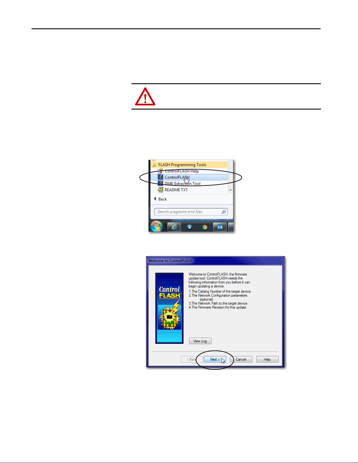
Chapter 5 Connect to the Controller
Use ControlFLASH Software to Update Firmware
To update your controller firmware with ControlFLASH software, complete
these steps
ATT EN TI ON : If the Secure Digital (SD) card is locked and set to load on
power-up, this update can be overwritten by firmware on the SD card.
1. Verify that the network connection is made and the network driver has
been configured in Linx-based communication software.
2. From the Windows Start Menu, click FLASH Programming Tools >
ControlFLASH.
3. Click Next.
66 Rockwell Automation Publication 5069-UM001G-EN-P - August 2020
Page 67
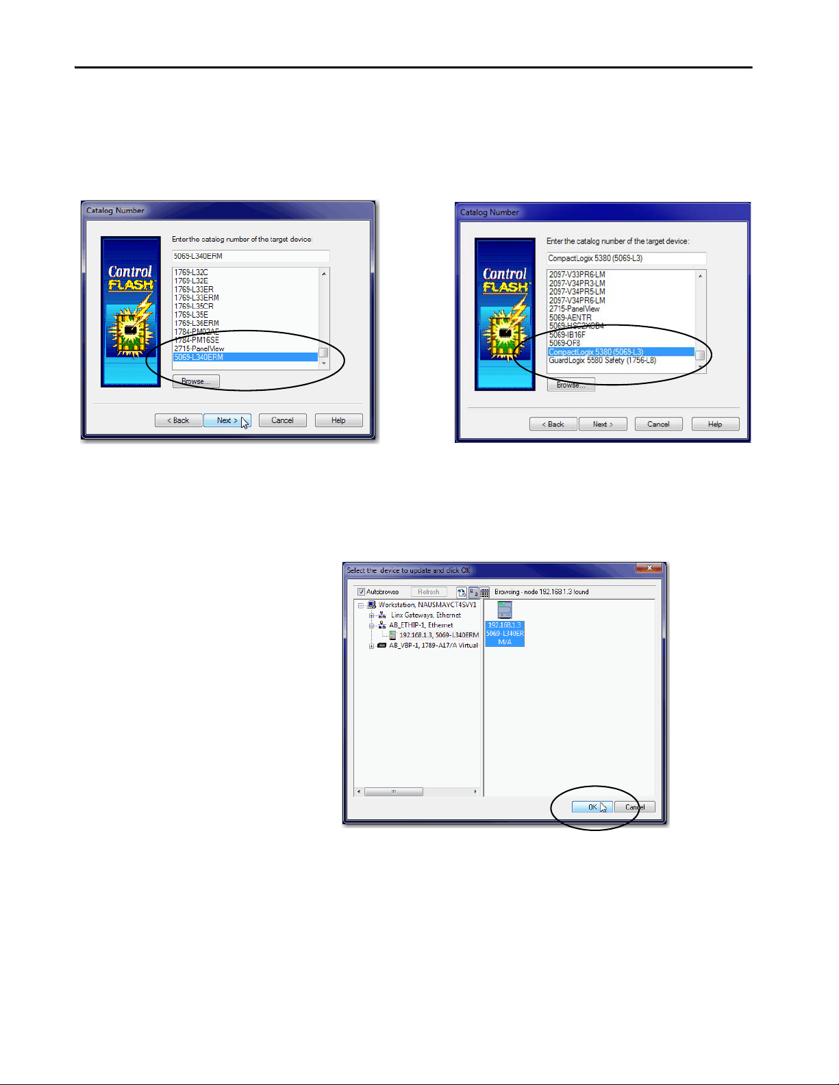
Connec t to the Controller Chapter 5
ControlFLASH software version 15.01.00 or laterControlFLASH software version 14.01.00 or earlier
4. Select the controller, and click Next.
ControlFLASH software version 15.01.00 or later has a family name
that applies to all controllers in that family, instead of individual
controller catalog numbers.
5. Expand the communication path and select the controller.
6. Click OK.
Rockwell Automation Publication 5069-UM001G-EN-P - August 2020 67
Page 68

Chapter 5 Connect to the Controller
7. Select the firmware revision and click Next.
If the firmware revision you need is not on the list, choose Show all
revisions.
TIP If you experience a Script File Error after you select the firmware revision
number, as shown, there can be an issue with your firmware files.
We recommend that you use the latest version of the ControlFLASH
software. If you are not, first upgrade to the latest version.
To resolve the issue, perform the following:
•Go to http://www.rockwellautomation.com/support/
the firmware revision you are trying to update. Replace the firmware
revision that you have previously installed with that posted on the
Technical Support website.
• If the replacement firmware revision does not resolve the anomaly,
contact Rockwell Automation Technical Support.
and download
.
8. On the Summary Screen, click Finish.
68 Rockwell Automation Publication 5069-UM001G-EN-P - August 2020
Page 69

Connec t to the Controller Chapter 5
9. When a confirmation dialog box appears, click Yes.
Before the firmware update begins, this dialog box appears. Take the
required action for your application. In this example, the upgrade
continues when OK is clicked.
The progress dialog box indicates the progress of the firmware update. The
controllers indicate progress in updates and blocks.
IMPORTANT Let the firmware update complete before you cycle power or
otherwise interrupt the update.
If the firmware update is interrupted, the controller reverts to boot
firmware, that is, revision 1.xxx.
When the update is complete, the Update Status dialog box indicates
that the update is complete.
10. Click OK.
11. Close the ControlFLASH software.
Rockwell Automation Publication 5069-UM001G-EN-P - August 2020 69
Page 70
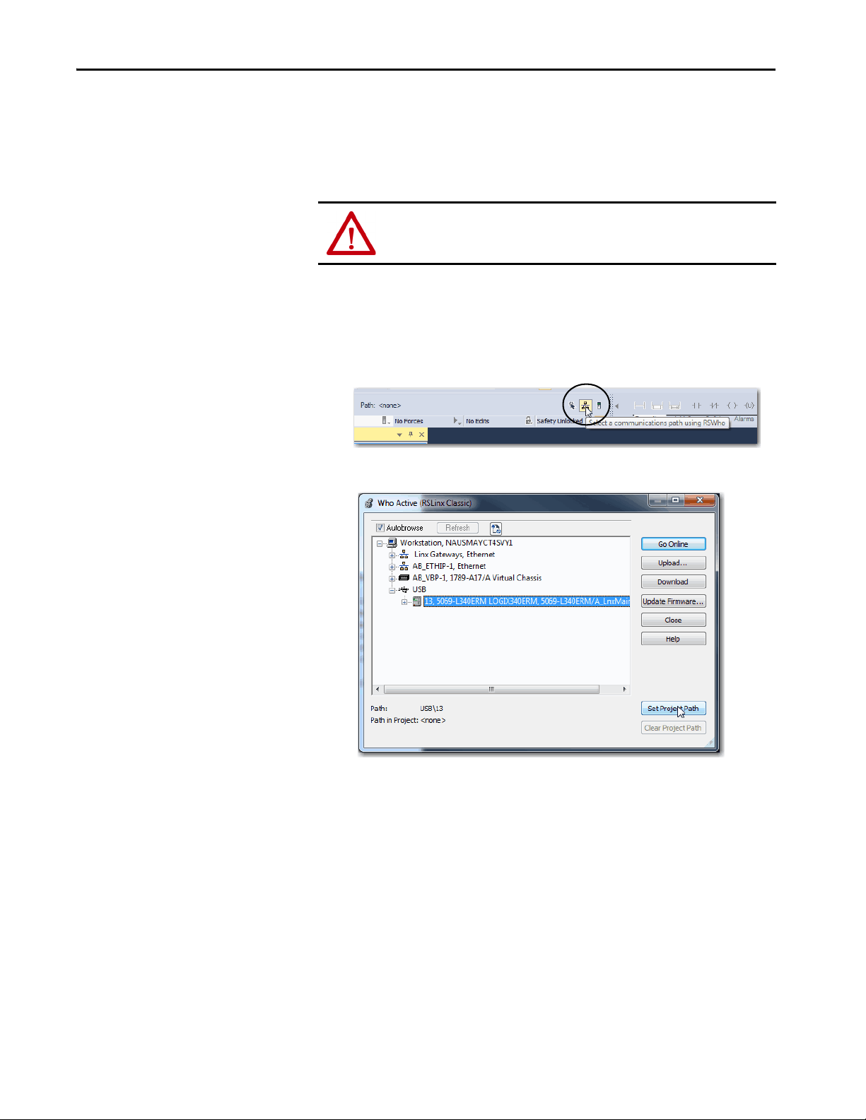
Chapter 5 Connect to the Controller
Use AutoFlash to Update Firmware
To update the controller firmware with the AutoFlash feature, complete these
steps.
ATT EN TI ON : If the Secure Di gital Ca rd is locked and set to load o n power-up,
this update can be overwritten by firmware on the SD card.
1. Verify that the network connection is made and the network driver has
been configured in Linx-based communication software.
2. Start the Logix Designer application, and create a project.
3. In the project, click RSWho.
4. Expand the communication path and select the controller.
70 Rockwell Automation Publication 5069-UM001G-EN-P - August 2020
Page 71

Connec t to the Controller Chapter 5
5. Select the controller and click Go Online.
6. On the Who Active dialog box, select the controller under the
communication driver you want to use, and click Update Firmware.
.
Rockwell Automation Publication 5069-UM001G-EN-P - August 2020 71
Page 72

Chapter 5 Connect to the Controller
7. On the Choose Firmware Revision dialog, browse to the location of the
firmware files (C:\Program Files (x86)\ControlFlash).
8. Select the firmware revision, and click Update.
9. On the Confirmation dialog, click Yes.
10. On the ControlFLASH Attention dialog, click OK.
A progress dialog box indicates the progress of the firmware update. The
controllers indicate progress in updates and blocks.
IMPORTANT Let the firmware update complete before you cycle power or
otherwise interrupt the update.
If the ControlFLASH update of the controller is interrupted, the
controllers revert to boot firmware, that is, revision 1.xxx.
When the update is complete, the Update Status dialog box indicates
that the update is complete.
11. Click OK on the Who Active dialog box.
72 Rockwell Automation Publication 5069-UM001G-EN-P - August 2020
Page 73

Connec t to the Controller Chapter 5
Controllers with Firmware Earlier than Revision 31
Applies to these controllers:
CompactLogix 5380
Controller State
Before Making
Changes
Out-of-box • No IP address set
Description Firmware Revision
• Unique MAC
addresss are used
for port A1 and
port A2,
respec tively
•Each port on the
controller is
DHCP-enabled
•Firmware revision
1.xxx
• No IP address is set
• One MAC address is
used for port A1/A2
• Port A1/A2 is
DHCP-enabled
•Firmware revision
1.xxx
of Update/Change
Revision 29.011 or
later
Revision 28.xxx
IMPORTANT: Only the
5069-L320ER and
5069-L340ERM
controllers support
revision 28.xxx.
For controllers with firmware revisions earlier than revision 31, you must be
aware of the following before you set the IP address and update the controller
firmware:
•Controller state before you make changes
• Firmware revision to which you are updating the controller
• Order in which you set the IP address and update the firmware revision
Task Completion Order Result of Completing Tasks in Order Indicated
1. Change the EtherNet/IP mode
from Dual-IP mode to Linear/
DLR mode.
2. Set IP address on port A1/A2.
3. Install controller firmware.
1. Install controller firmware.
2. Set IP addresses on port A1 and
port A2.
1. Set IP address on port A1/A2.
2. Install controller firmware.
1. Install controller firmware.
2. Set IP address on port A1/A2.
• The controller EtherNet/IP mode is automatically set to Dual-IP
mode.
• The port A1/A2 IP address, network mask, default gateway
settings are applied to port A2.
Other port A1/A2 settings, for example, DNS servers and
Domain Name, are lost.
• The port A1/A2 MAC address is applied to port A1, and a
separate MAC address is applied to Port A2.
• You must set the IP address configuration
• The controller EtherNet/IP mode remains set to Dual-IP mode
after the firmware is installed.
The controller EtherNet/IP mode is set to Dual-IP mode when it
is in the out-of-box state.
• A unique MAC address is assigned to each controller por t.
• You must set the IP address and related parameters for port A1
(enterprise port) and port A2 (device-level port).
• The controller EtherNet/IP mode is automatically set to Linear/
DLR mode.
• The IP address settings on port A1/A2 remain the same.
Rockwell Automation Publication 5069-UM001G-EN-P - August 2020 73
Page 74

Chapter 5 Connect to the Controller
Controller State
Before Making
Changes
Operating • IP address set on
Description Firmware Revision
port A1/A2
•Firmware revision
28.xxx is installed
• Controller operates
in Linear/DLR mode
• IP address set on
port A1/A2
•Firmware revision
29.011 or later is
installed
• Controller operates
in Dual-IP mode
• IP addresses are set
on port A1 and
port A2
•Firmware revision
29.011 or later is
installed
of Update/Change
Revision 29.011 or
later
Downgrade to revision
28.xxx
IMPORTANT: You can
perform this download
only on the 5069L320ER and 5069L340ERM controllers.
Task Completion Order Result of Completing Tasks in Order Indicated
Update controller firmware • EtherNet/IP mode changes to Dual-IP mode.
• The port A1/A2 IP address, network mask, default gateway
settings are applied to port A2.
Other port A1/A2 settings, for example, DNS servers and
Domain Name, are lost.
• The port A1/A2 MAC address is applied to port A1. A separate
MAC address is applied to Port A2.
• The I/O Configuration section in the Logix Designer application
project is automatically assigned to port A1.
You can change the I/O configuration in the Logix Designer
application project to assign it to port A2.
• If necessary, you can change to DLR/Linear mode after the
firmware revision update.
Downgrade contro ller firmware • Et herNet/IP mo de remains in Linear/D LR mode
• IP address settings remain the same
Downgrade controller firmware • EtherNet/IP mode automatically changes from Dual-IP mode to
Linear/DLR mode
• After the change is made, the port A2 Internet Protocol
configuration is applied to the A1/A2 port.
74 Rockwell Automation Publication 5069-UM001G-EN-P - August 2020
Page 75

Start to Use the Controller
Top ic Pag e
Create a Logix Designer Application Project 75
Additional Configuration for a Compact GuardLogix Controller 78
Go Online with the Controller 85
Download to the Controller 92
Upload from the Controller 95
Choose the Controller Operation Mode 99
Change Control ler Configuration 102
Reset Button 103
Chapter 6
Create a Logix Designer Application Project
Applies to these controllers:
CompactLogix™ 5380
Compact GuardLogix® 5380 SIL 2
Compact GuardLogix 5380 SIL 3
Out-of-the-box, the controller does not contain a Studio 5000 Logix Designer®
application project. To create a Logix Designer application project, complete
these steps.
1. Start the application. The Logix Designer application is part of the
Studio 5000® environment.
Rockwell Automation Publication 5069-UM001G-EN-P - August 2020 75
Page 76
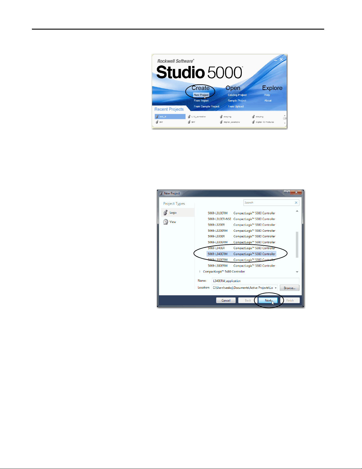
Chapter 6 Start to Use the Controller
2. Click New Project.
3. On the New Project dialog box, complete these steps:
a. Select the controller.
b. Name the project.
c. Browse to the location where the project file is created.
d. Click Next.
76 Rockwell Automation Publication 5069-UM001G-EN-P - August 2020
Page 77

Start to Use the Controller Chapter 6
4. Select the following:
• Revision
• Security Authority (optional)
• Secure With (only available if Security Authority is used)
For information on security, refer to the Logix 5000™ Controllers
Security Programming Manual, publication 1756-PM016
.
5. Click Finish.
Rockwell Automation Publication 5069-UM001G-EN-P - August 2020 77
Page 78

Chapter 6 Start to Use the Controller
Additional Configuration for a Compact GuardLogix Controller
Applies to these controllers:
Compact GuardLogix 5380 SIL 2
Compact GuardLogix 5380 SIL 3
Compact GuardLogix 5380 controllers require additional configuration after
you create the project. These topics describe how to configure the additional
parameters.
Top ic Pa ge
Assign the Safety Network Number (SNN) 78
Go Online with the Controller 85
For a Compact GuardLogix controller, the Logix Designer application creates
a safety task and a safety program. A main Ladder Diagram safety routine that
is called MainRoutine is also created within the safety program.
A red bar under the icon distinguishes safety programs and routines from
standard project components in the Controller Organizer.
Assign the Safety Network Number (SNN)
When you create controller projects, the Studio 5000 Logix Designer
application generates an SNN value automatically whenever it recognizes a
new subnet that contains CIP Safety™ devices:
• Each CIP Safety-capable port on the controller is assigned an SNN. The
Compact GuardLogix 5380 controllers have up to three safety network
numbers: a separate SNN for each Ethernet port, and one SNN for the
backplane.
• If a bridge or adapter device is in the I/O tree and a child CIP Safety
device is added, the subnet that is created by the bridge or adapter is
assigned an SNN.
For typical users, the automatic assignment of a time-based SNN is sufficient.
However, manual assignment of the SNN is required if the following is true:
• One or more controller ports are on a CIP Safety subnet that already has
an established SNN.
• A safety project is copied to another hardware installation within the
same routable CIP Safety system.
78 Rockwell Automation Publication 5069-UM001G-EN-P - August 2020
Page 79

Start to Use the Controller Chapter 6
Rockwell Automation recommends changing each SNN to the SNN already
established for that subnet, if one exists. That way, devices created later in the
project are automatically assigned the correct SNN.
For information regarding whether the controller or Ethernet ports are being
added to existing subnets, see the GuardLogix 5580 and Compact GuardLogix
5380 Controller Systems Safety Reference Manual, publication 1756-RM012.
Each safety network must have a unique safety network number. You must be
sure that a unique SNN is assigned to each CIP Safety network that contains
safety devices.
TIP Multiple safety network numbers can be assigned to a CIP Safety subnet or a
ControlBus™ chassis that contains multiple safety devices. However, for simplicity, we
recommend that each CIP Safety subnet has only one unique SNN.
For an explanation on the Safety Network Number, see the GuardLogix 5580
and Compact GuardLogix 5380 Controller Systems Safety Reference Manual,
publication 1756-RM012.
The SNN can be software-assigned (time-based) or user-assigned (manual).
These two formats of the SNN are described in the following sections:
• Automatic Assignment of Time-based SSN
on page 80
• Manual Assignment of SSN on page 81
Rockwell Automation Publication 5069-UM001G-EN-P - August 2020 79
Page 80
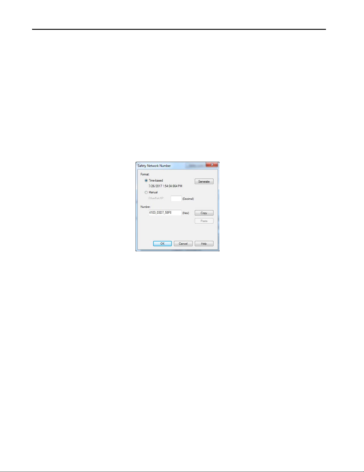
Chapter 6 Start to Use the Controller
Automatic Assignment of Time-based SSN
When a new controller or device is created, a time-based SNN is automatically
assigned.
• Devices that are created directly under the controller port default to
having the same SNN as that port on the controller.
• For devices not directly under a controller port, subsequent new safety
device additions to the same CIP Safety network are assigned the same
SNN defined within the lowest address on that CIP Safety network.
The time-based format sets the SNN value as the date and time when the
number was generated, according to the computer running the configuration
software.
Figure 18 - Time-based Format
80 Rockwell Automation Publication 5069-UM001G-EN-P - August 2020
Page 81

Start to Use the Controller Chapter 6
Manual Assignment of SSN
Manual assignment is useful if you lay out your network and put the SNNs on
your network diagram. It may be easier to read SNNs from a diagram than it is
to copy and paste them from multiple projects.
Manual assignment of the SNN is required if the following is true:
• One or more controller ports are on a CIP Safety subnet that already has
an established SNN.
• A safety project is copied to another hardware installation within the
same routable CIP Safety system.
IMPORTANT If you assign an SNN automatically or manually, make sure that system
expansion does not result in a duplication of SNN and unique node reference
combinations.
A warning appears if your project contains duplicate SNN and unique node
reference combinations. You can still verify the project, but Rockwell
Automation recommends that you resolve the duplicate combinations.
However, there can be safety devices on the routable safety network that have
the same SNN and node address and are not in the project. In this case, these
safety devices are unknown to the Logix Designer application, and you will
not see a warning.
If two different devices have the same node references, the safety system
cannot detect a packet received by one device that was intended for the other
device.
If there are duplicate unique node references, as the system user, you are
responsible for proving that an unsafe condition cannot result.
Rockwell Automation Publication 5069-UM001G-EN-P - August 2020 81
Page 82

Chapter 6 Start to Use the Controller
Follow these steps to change the controller SNNs to a manual assignment:
1. On the Online toolbar, click the Controller Properties icon
2. On the Controller Properties dialog, click the Safety tab.
3. On the Safety tab, click to the right of the safety network number
for the port that you want to change.
4. On the Safety Network Number dialog box, select Manual
5. Enter the SNN as a value from 1…9999 (decimal).
6. Click OK.
82 Rockwell Automation Publication 5069-UM001G-EN-P - August 2020
Page 83

Start to Use the Controller Chapter 6
Copy and Paste a Safety Controller Safety Network Number (SNN)
If you must apply an SNN to other safety controllers, you can copy and paste
the SNN. There are multiple ways to copy and paste safety controller SNNs.
Copy a Safety Controller SNN
From the Controller Properties Safety Tab:
1. On the Safety tab, click in the SNN field that you want to copy.
2. Press Ctrl-C to copy the SNN.
From the Safety Network Number dialog:
1. On the Controller Properties dialog, click the Safety tab.
2. Click to the right of the safety network number to open the Safety
Network Number dialog.
3. On the Safety Network Number dialog, either click Copy, or click in the
SNN field and Press Ctrl-C.
Rockwell Automation Publication 5069-UM001G-EN-P - August 2020 83
Page 84

Chapter 6 Start to Use the Controller
Paste a Safety Controller SNN
1. On the Controller Properties dialog, click the Safety tab.
2. Click to the right of the safety network number to open the Safety
Network Number dialog.
3. On the Safety Network Number dialog, either click Paste, or click in the
SNN field and Press Ctrl-V.
4. Click OK.
5. On the Controller Properties Safety tab, click OK.
84 Rockwell Automation Publication 5069-UM001G-EN-P - August 2020
Page 85

Start to Use the Controller Chapter 6
Go Online with the Controller
Applies to these controllers:
CompactLogix 5380
Compact GuardLogix 5380 SIL 2
Compact GuardLogix 5380 SIL 3
To go online with the controller, you must first specify a communication path
in the Logix Designer application.
TIP For this section, the USB port was chosen as the communication path.
Another path through the embedded Ethernet ports is also possible.
Use RSWho
1. Open or create a Logix Designer application project.
2. In the application, click RSWho.
3. Expand the communication path and select the controller.
4. If you want to store the path in the project file, click Set Project Path.
If you store the project path in the project, you do not have to choose the
path each time you go online.
Rockwell Automation Publication 5069-UM001G-EN-P - August 2020 85
Page 86

Chapter 6 Start to Use the Controller
5. After you choose the communication path, click Go Online in the
Who Active dialog box.
Go Online uses the highlighted node in the Who Active tree, regardless
of the setting for Path in Project. For more information on the Who
Active dialog box, see the Logix Designer Online Help.
See Additional Considerations for Going Online with a Controller on
page 88.
86 Rockwell Automation Publication 5069-UM001G-EN-P - August 2020
Page 87

Start to Use the Controller Chapter 6
Use a Recent Communications Path
You can also select a recent communications path and go online or apply it to
your project.
1. Click the Recent Communication Path button next to the Path bar.
2. On the Select Recent Communications Path dialog box, choose
the path.
3. To store the path in your project, click Set Project Path.
4. Click Go Online.
For more information on the Select Recent Communications Path dialog box,
see the Logix Designer Online Help.
Once you have established a communication path, then you can choose Go
Online from the Controller Status menu when you are working in the project.
See Additional Considerations for Going Online with a Controller on
page 88.
Rockwell Automation Publication 5069-UM001G-EN-P - August 2020 87
Page 88

Chapter 6 Start to Use the Controller
Additional Considerations for Going Online with a Controller
Applies to these controllers:
CompactLogix 5380
Compact GuardLogix 5380 SIL 2
Compact GuardLogix 5380 SIL 3
The Logix Designer application determines whether you can go online with a
target controller based on whether the offline project is new, or whether
changes occurred in the offline project.
•If the project is new, you must first download the project to the
controller.
• If changes occurred to the project, you are prompted to upload or
download.
• If no changes occurred, you can go online to monitor the execution of
the project.
TIP For information on uploading a project, downloading a project, and the
upload and download dialog boxes, see the Logix Designer Online Help.
A number of factors affect these processes, including the Match Project to
Controller feature and the Firmware Revision Match feature.
For Compact GuardLogix controllers, additional considerations include the
safety status and faults, the existence of a safety signature, and the
safety-lock/-unlock status of the project and the controller. See Additional
Considerations for Going Online with a Compact GuardLogix Controller on
page 90.
Match Project to Controller
The Match Project to Controller feature affects the download, upload, and go
online processes of standard and safety projects. This feature is on the
Controller Properties Advanced tab.
If the Match Project to Controller feature is enabled in the offline project, the
Logix Designer application compares the serial number of the controller in the
offline project to that of the connected controller. If they do not match, you
must cancel the download/upload, connect to the correct controller, or
confirm that you are connected to the correct controller that updates the serial
number in the project to match the target controller.
88 Rockwell Automation Publication 5069-UM001G-EN-P - August 2020
Page 89

Start to Use the Controller Chapter 6
Firmware Revision Matching
Firmware revision matching affects the download process. If the revision of the
controller does not match the revision of the project, you are prompted to
update the firmware of the controller. The Logix Designer application lets you
update the firmware as part of the download sequence.
IMPORTANT To update the firmware of the controller, first install a firmware update
kit. An update kit ships on a supplemental DVD along with the Studio
5000® environment.
TIP You can also upgrade the firmware by choosing ControlFLASH™ from the Tools
menu in the Logix Designer application.
Rockwell Automation Publication 5069-UM001G-EN-P - August 2020 89
Page 90

Chapter 6 Start to Use the Controller
Additional Considerations for Going Online with a Compact GuardLogix Controller
Applies to these controllers:
Compact GuardLogix 5380 SIL 2
Compact GuardLogix 5380 SIL 3
You can upload program logic and go online regardless of safety status. Safety
status and faults only affect the download process.
You can view the safety status via the Safety tab on the Controller Properties
dialog box.
Safety Signature and Safety-locked and -unlocked Status
The existence of a safety signature and the safety-locked or -unlocked status of
the controller affect both the upload and download processes.
The safety signature and the safety lock status are uploaded with the project.
For example, if the project in the controller was safety-unlocked, the offline
project remains safety-unlocked following the upload, even if it was locked
before the upload.
Following an upload, the safety signature in the offline project matches the
controller safety signature.
The safety lock status always uploads with the project, even when there is no
safety signature.
The existence of a safety signature, and the controller safety-lock status,
determines if a download can proceed.
Table 3 - Effect of Safety-lock and safety signature on Download Operation
Safety-lock Status Safety Signature Status Download Functionality
Safety signature in the offline project matches
the safety signature in the controller.
Controller safety-unlocked
Safety signatures do not match. If the controller had a safety signature, it is automatically deleted, and the entire project is
Safety signatures match. If the offline project and the controller are safety-locked, all standard project components are
Controller safety-locked
Safety signatures do not match. You must first safety-unlock the controller to allow the download to proceed. If the controller
The entire application downloads. Safety tags are reinitialized to the values they had when the
safety signature was created. Safety lock status matches the status in the offline project. The
safety signature does not change.
downloaded. Safety lock status matches the status in the offline project.
downloaded and safety tags are reinitialized to the values they had when the safety signature
was created.
If the offline project is not safety-locked, but the controller is, the download is blocked and you
must first unlock the controller to allow the download to proceed.
had a safety signature, it is automatically deleted, and the entire project is downloaded. Safety
lock status matches the status in the offline project.
90 Rockwell Automation Publication 5069-UM001G-EN-P - August 2020
Page 91

Checks for Going Online with a GuardLogix Controller
For a safety project, the Logix Designer application checks for the following:
• Do the offline project and controller serial numbers match (if Project
to Controller Match is selected)?
• Does the offline project contain changes that are not in the controller
project?
• Do the revisions of the offline project and controller firmware
match?
• Are either the offline project or the controller safety-locked?
• Do the offline project and the controller have compatible safety
signatures?
Table 4 - Connect to the Controller with a Safety Project
If the Software Indicates Then
Unable to connect to controller. Mismatch between the offline project and the
controller serial number. Selected controller can be the wrong controller.
Unable to connect to controller. The revision of the offline project and the controller
firmware are not compatible.
You must upload or download to go online by using the open project. Choose one of the following options:
Unable to connect in a manner that preserves safety signature. The firmware minor
revision on the controller is not compatible with safety signature in offline project.
Unable to connect to controller. Incompatible safety signature cannot be deleted while
project is safety-locked.
Connect to the correct controller, select another project file, or choose the Update
project serial number checkbox and choose Go Online… to connect to the controller
and update the offline project serial number to match the controller.
Choose one of the following options:
• Choose Update Firmware. Choose the required revision and click Update. Click Yes to
confirm your selection.
IMPORTANT: The online project is deleted.
• To preserve the online project, cancel the online process and install a version of the
Studio 5000 environment that is compatible with the firmware revision of your
controller.
• Upload to update the offline project.
• Download to update the controller project.
• Choose File to select another offline project.
• To preserve the safety signature when the firmware minor revision is incompatible,
update the firmware revision in the controller to exactly match the offline project.
Then go online to the controller.
• To proceed with the download despite the safety signature incompatibility, click
Download. The safety signature is deleted.
IMPORTANT: The safety system requires revalidation.
Cancel the online process. You must safety-unlock the offline project before attempting
to go online.
Start to Use the Controller Chapter 6
When the controller and the Logix Designer application are online, the safetylocked status and safety signature of the controller match the controller
project. The safety-lock status and safety signature of the offline project are
overwritten by the controller. If you do not want the changes to the offline
project to be permanent, do not save the project file following the go online
process.
Rockwell Automation Publication 5069-UM001G-EN-P - August 2020 91
Page 92

Chapter 6 Start to Use the Controller
Download to the Controller
Applies to these controllers:
CompactLogix 5380
Compact GuardLogix 5380 SIL 2
Compact GuardLogix 5380 SIL 3
When you download a project to the controller, it copies the project from the
Logix Designer application onto the controller. You can download a project in
two ways:
• Use Who Active on page 92
• Use the Controller Status Menu on page 93
Use Who Active
You can use the features of the Who Active dialog box to download to the
controller after you have set the communication path. Complete these steps to
download to the controller.
1. After choosing the communication path, click Download in the
Who Active dialog box.
2. After reading the warnings in the Download dialog box, click
Download.
92 Rockwell Automation Publication 5069-UM001G-EN-P - August 2020
Page 93

Start to Use the Controller Chapter 6
Use the Controller Status Menu
After you choose a communication path in the Logix Designer application, you
can use the Controller Status menu to download to the controller. To
download, from the Controller Status menu, choose Download.
Figure 19 - Download Via the Controller Status Menu
TIP After the download completes, the project name appears on the scrolling status
display.
Additional Considerations for Download to a Compact GuardLogix Controller
Applies to these controllers:
Compact GuardLogix 5380 SIL 2
Compact GuardLogix 5380 SIL 3
For a safety project, the Logix Designer application compares the following
information in the offline project and the controller:
• Controller serial number (if project to controller match is selected)
• Firmware major and minor revisions
•Safety status
• Safety signature (if one exists)
• Safety-lock status
After the checks pass, a download confirmation dialog box appears. Click
Download.
Rockwell Automation Publication 5069-UM001G-EN-P - August 2020 93
Page 94

Chapter 6 Start to Use the Controller
The Logix Designer application displays status messages in the download
dialog, progress screen, and the Errors window.
If the Software Indicates: Then:
Unable to download to the controller. Mismatch between the offline project
and the controller serial number. Selected controller can be the wrong
controller.
Unable to download to the controller. The major revision of the offline project
and the controller firmware are not compatible.
Unable to download to controller. The internal safety partner hardware has
failed.
Unable to download to the controller. Safety partnership has not been
established.
Unable to download to controller. Incompatible safety signature cannot be
deleted while the project is safety-locked.
Cannot download in a manner that preserves the safety signature. Controller
firmware minor revision is not compatible with safety signature in offline
project.
Unable to download to controller. Controller is locked. Controller and offline
project safety signatures do not match.
Downloading safety signature... The safety signature is present in the offline project and is downloading.
Connect to the correct controller or verify that this is the correct controller. If it is the correct
controller, check the Update project serial number checkbox to allow the download to proceed.
The project serial number is modified to match the controller serial number.
Choose Update Firmware. Choose the required revision and click Update. Click Yes to confirm your
selection.
Replace the Compact GuardLogix SIL 3 controller.
Cancel the download process and attempt a new download to the Compact GuardLogix SIL 3
controller.
Cancel the download. To download the project, you must safety-unlock the offline project, delete
the safety signature, and download the project.
IMPORTANT: The safety system requires revalidation.
• If the firmware minor revision is incompatible, to preserve the safety signature, update the
firmware revision in the controller to exactly match the offline project. Then download the
offline project.
• To proceed with the download despite the safety signature incompatibility, click Download.
The safety signature is deleted.
IMPORTANT: The safety system requires revalidation.
Choose Unlock. The Safety Unlock for Download dialog box appears. If the Delete Signature
checkbox is selected and you choose Unlock, click Yes to confirm the deletion.
IMPORTANT: The safety system requires revalidation.
Following a successful download, the safety-locked status and safety signature
of the controller match the project that was downloaded. Safety data is
initialized to the values that existed when the safety signature was created.
94 Rockwell Automation Publication 5069-UM001G-EN-P - August 2020
Page 95

Start to Use the Controller Chapter 6
Upload from the Controller
Applies to these controllers:
CompactLogix 5380
Compact GuardLogix 5380 SIL 2
Compact GuardLogix 5380 SIL 3
When you upload a project from the controller, it copies the project from the
controller to the Logix Designer application. To upload a project, use one of
these methods:
• Use Who Active on page 95
• Use the Controller Status Menu on page 96
Use Who Active
You can use the features of the Who Active dialog box to upload from your
controller after you have set the communication path. Complete these steps to
upload from the controller.
1. In the Logix Designer application project, click RSWho.
2. Expand the communication path and select the controller.
3. Click Upload on the Who Active dialog box.
Rockwell Automation Publication 5069-UM001G-EN-P - August 2020 95
Page 96

Chapter 6 Start to Use the Controller
4. On the Connected to Upload dialog box, verify that the project is the
one you want to upload.
5. Click Upload.
For more information on the Connected To upload dialog box, see the Logix
Designer Online Help.
Use the Controller Status Menu
After you have chosen a communication path in the Logix Designer
application, you can use the Controller Status menu to upload from the
controller.
1. From the Controller Status pull-down menu, choose Upload.
96 Rockwell Automation Publication 5069-UM001G-EN-P - August 2020
Page 97

Start to Use the Controller Chapter 6
2. On the Connected to Upload dialog box, verify that the project is the
one you want to upload.
3. Click Upload.
Rockwell Automation Publication 5069-UM001G-EN-P - August 2020 97
Page 98

Chapter 6 Start to Use the Controller
Additional Considerations for
Upload to a Compact
For a safety project, the Logix Designer application compares the following
information in the project and the controller:
• Controller serial number (if project to controller match is selected)
GuardLogix Controller
Applies to these controllers:
Compact GuardLogix 5380 SIL 2
Compact GuardLogix 5380 SIL 3
• Open project to the controller project
• Firmware major and minor revisions
• Safety signature (if one exists)
IMPORTANT An upload is allowed regardless of the Safety status and the Safety Locked
state of the offline project and controller. The locked status follows the state
of the uploaded project.
Table 5 - Upload Behavior
Upload Behavior: Response:
If the project to controller match is enabled, the Logix Designer application
checks whether the serial number of the open project and the seri al number of
the controller match.
The Logix Designer application checks whether the open project matches the
controller project.
The Logix Designer application checks for changes in the offline project. • If there are no changes in the offline project, you can go online without uploading. Click Go
Uploading safety signature... This message appears during the upload only if a safety signature matching the one in the
• Connect to the correct controller or verify that this is the correct controller.
• Select a new project to upload into or select another project by choosing Select File.
• If it is the correct controller, select the Update projec t serial number checkbox to allow the
download to proceed. The project serial number is modified to match the controller serial
number.
• If the projects do not match, you must select a matching file or cancel the upload process.
• If the projects match, the software checks for changes in the offline (open) project.
Online.
• If there are changes in the open projec t that are not present in the controller, you can choose
to upload the project, cancel the upload, or select another file.
controller does not exist in the offline project.
If you choose Upload, the standard and safety applications are uploaded.
If a safety signature exists, it is also uploaded. The safety-lock status of
the project reflects the original status of the online (controller) project.
TIP Before the upload, if an offline safety signature exists, or the offline project is
safety-locked but the controller is safety-unlocked or has no safety signature,
the offline safety signature and safety-locked state are replaced by the online
values (safety-unlocked with no safety signature). If you do not want to make
these changes permanent, do not save the offline project following the
upload.
98 Rockwell Automation Publication 5069-UM001G-EN-P - August 2020
Page 99
Start to Use the Controller Chapter 6
Choose the Controller
Use this table as a reference when determining your controller operation mode.
Operation Mode
Applies to these controllers:
CompactLogix 5380
Compact GuardLogix 5380 SIL 2
Compact GuardLogix 5380 SIL 3
Mode Switch
Position
RUN Run mode—The controller is actively
REM Remote Run mode—This mode is
PROG Program mode—This controller mode
(1) Moving the mode switch from Run to Remote leaves the controller in the Remote Run mode, whil e moving the switch from Program to Remote leaves the controller in the Remote Program mode. You
cannot choose Remote Test mode by the mode switch alone, it is only available via the Logix Designer application.
Available Controller Modes In This Mode You Can: In This Mode You Cannot:
(1)
controlling the process/machine. Projects
cannot be edited in the Logix Designer
application when in Run mode.
identical to Run mode except you can edit
the project online, and change the
controller mode through the Logix
Designer application.
Remote Program mode—This mode
functions like Program mo de, except you
can change the controller mode through
the Logix Designer application.
Remote Test mode—This controller
mode executes code, but I/O is not
controlled. You can edit the project
online, and change the controller mode
through the Logix Designer application.
Output modules are commanded to their
Program mode state (on, off, or hold).
does not execute code or control I/O, but
editing operations are available.
Output modules are commanded to their
Program mode state (On, Off, or Hold).
In this position, controller modes cannot
be changed through the Logix Designer
application.
• Turn outputs to the state
commanded by the logic of the
project.
•Execute (scan) tasks
• Send messages
• Send and receive data in response to
a message from another controller
• Produce and consume tags
• Turn outputs to the state
commanded by the logic of the
project.
•Execute (scan) tasks
• Change the mode of the controller
via the Logix Designer application
• While online, edit the project
• Send messages
• Send and receive data in response to
a message from another controller
• Produce and consume tags
• Turn outputs to their configured
state for Program mode
• Change the mode of the controller
via the Logix Designer application
• Download a project
• Schedule a ControlNet network
• While online, edit the project
• Send and receive data in response to
a message from another controller
• Produce and consume tags
• Turn outputs to their configured
state for Program mode
•Execute (scan) tasks
• Change the mode of the controller
via the Logix Designer application
• While online, edit the project
• Send messages
• Send and receive data in response to
a message from another controller
• Produce and consume tags
• Turn outputs to their configured
state for Program mode
• Download a project
• Schedule a ControlNet network
• While online, edit the project
• Send and receive data in response to
a message from another controller
• Produce and consume tags
• Turn outputs to their configured
state for Program mode
• Change the mode of the
controller via the Logix Designer
application
• Download a project
• Schedule a ControlNet® network
• While online, edit the project
• Turn outputs to their configured
state for Program mode
• Download a project
• Schedule a ControlNet network
• Turn outputs to the state
commanded by the logic of the
project.
•Execute (scan) tasks
• Turn outputs to the state
commanded by the logic of the
project.
• Download a project
• Schedule a ControlNet network
• Send messages
• Turn outputs to the state
commanded by the logic of the
project.
•Execute (scan) tasks
• Change the mode of the
controller via the Logix Designer
application
• Send messages
ATTENTION:
Run mode is used only when all
conditions are safe.
You are able to modify a project
file online in Remote Run mode.
Be sure to control outputs with
care to avoid injur y to personnel
and damage to equipment.
Outputs are commanded to
their Program mode state,
which can cause a dangerous
situation.
Do not use Program mode as an
emergency stop (E-stop).
Program mode is not a safety
device.
Outputs are commanded to
their Program mode state,
which can cause a dangerous
situation.
Rockwell Automation Publication 5069-UM001G-EN-P - August 2020 99
Page 100
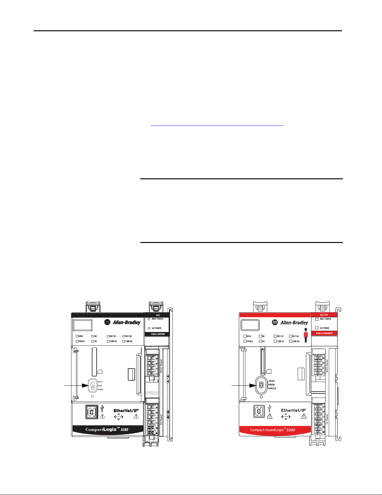
Chapter 6 Start to Use the Controller
Mode Switch Mode Switch on both
Compact GuardLogix SIL 2
and SIL 3 controllers.
Use the Mode Switch to Change the Operation Mode
To change the operating mode, use the controller mode switch. The controller
mode switch provides a mechanical means to enhance controller and control
system security. You must physically move the mode switch on the controller to
change its operating mode from RUN, to REM, or to PROG.
When the mode switch on the controller is set to RUN mode, features like
online editing, program downloads, and firmware updates are prohibited.
See Choose the Controller Operation Mode on page 99
features.
The mode switch can complement other authorization and authentication
methods that similarly control user-access to the controller, such as the
FactoryTalk® Security service.
IMPORTANT During runtime, we recommend that you place the controller mode switch in
RUN mode. This can help discourage unauthorized access to the controller or
potential tampering with the program of the controller, configuration, or
device firmware.
Place the mode switch in REM or PROG mode during controller
commissioning and maintenance and whenever temporary access is
necessary to change the program, configuration, or firmware of the product.
for a list of prohibited
The mode switch on the front of the controller can be used to change the
controller to one of these modes:
•Run (RUN)
•Remote (REM)
•Program (PROG)
100 Rockwell Automation Publication 5069-UM001G-EN-P - August 2020
 Loading...