

Page 1

Compact 5000 EtherNet/IP
Adapters
Catalog Numbers 5069-AENTR, 5069-AENTRK, 5069-AEN2TR
User Manual
Original Instructions
Page 2
Compact 5000 EtherNet/IP Adapters User Manual
Important User Information
Read this document and the documents listed in the additional resources section about installation, configuration, and
operation of this equipment before you install, configure, operate, or maintain this product. Users are required to familiarize
themselves with installation and wiring instructions in addition to requirements of all applicable codes, laws, and standards.
Activities including installation, adjustments, putting into service, use, assembly, disassembly, and maintenance are required to
be carried out by suitably trained personnel in accordance with applicable code of practice.
If this equipment is used in a manner not specified by the manufacturer, the protection provided by the equipment may be
impaired.
In no event will Rockwell Automation, Inc. be responsible or liable for indirect or consequential damages resulting from the use
or application of this equipment.
The examples and diagrams in this manual are included solely for illustrative purposes. Because of the many variables and
requirements associated with any particular installation, Rockwell Automation, Inc. cannot assume responsibility or liability for
actual use based on the examples and diagrams.
No patent liability is assumed by Rockwell Automation, Inc. with respect to use of information, circuits, equipment, or software
described in this manual.
Reproduction of the contents of this manual, in whole or in part, without written permission of Rockwell Automation, Inc., is
prohibited.
Throughout this manual, when necessary, we use notes to make you aware of safety considerations.
WARNING: Identifies information about practices or circumstances that can cause an explosion in a hazardous environment, which
may lead to personal injury or death, property damage, or economic loss.
ATTENTION: Identifies information about practices or circumstances that can lead to personal injury or death, property damage,
or economic loss. Attentions help you identify a hazard, avoid a hazard, and recognize the consequence.
IMPORTANT Identifies information that is critical for successful application and understanding of the product.
Labels may also be on or inside the equipment to provide specific precautions.
SHOCK HAZARD: Labels may be on or inside the equipment, for example, a drive or motor, to alert people that dangerous voltage
may be present.
BURN HAZARD: Labels may be on or inside the equipment, for example, a drive or motor, to alert people that surfaces may reach
dangerous temperatures.
ARC FLASH HAZARD: Labels may be on or inside the equipment, for example, a motor control center, to alert people to potential Arc
Flash. Arc Flash will cause severe injury or death. Wear proper Personal Protective Equipment (PPE). Follow ALL Regulatory
requirements for safe work practices and for Personal Protective Equipment (PPE).
2 Rockwell Automation Publication 5069-UM007B-EN-P - January 2021
Page 3

Compact 5000 EtherNet/IP
Adapter Features
Table of Contents
Preface . . . . . . . . . . . . . . . . . . . . . . . . . . . . . . . . . . . . . . . . . . . . . . . . . . . . . . . . . 5
Summary of Changes. . . . . . . . . . . . . . . . . . . . . . . . . . . . . . . . . . . . . . . . . . . . . 5
Additional Resources . . . . . . . . . . . . . . . . . . . . . . . . . . . . . . . . . . . . . . . . . . . . . 6
Chapter 1
Compact 5000 EtherNet/IP Adapter Features . . . . . . . . . . . . . . . . . . . . . . . 7
Minimum Software Requirements. . . . . . . . . . . . . . . . . . . . . . . . . . . . . . . . . 8
EtherNet/IP Features. . . . . . . . . . . . . . . . . . . . . . . . . . . . . . . . . . . . . . . . . . . . . 8
Protected Mode With 5069-AENTR Adapter . . . . . . . . . . . . . . . . . . . . . . . . 8
Enter and Exit Implicit Protected Mode. . . . . . . . . . . . . . . . . . . . . . . . . 9
Enter and Exit Explicit Protected Mode . . . . . . . . . . . . . . . . . . . . . . . . . 9
Restrictions Imposed By Implicit Protected Mode . . . . . . . . . . . . . . 10
Restrictions Imposed by Explicit Protected Mode . . . . . . . . . . . . . . . 10
Perform Tasks When Not Restricted. . . . . . . . . . . . . . . . . . . . . . . . . . . 10
Secure Digital Card . . . . . . . . . . . . . . . . . . . . . . . . . . . . . . . . . . . . . . . . . . . . . 12
Conformal Coating with 5069-AENTRK Adapter . . . . . . . . . . . . . . . . . . . 13
Compact 5000 EtherNet/IP
Adapter Power Requirements
Chapter 2
Two Types of Power . . . . . . . . . . . . . . . . . . . . . . . . . . . . . . . . . . . . . . . . . . . . . 15
Power Connectors . . . . . . . . . . . . . . . . . . . . . . . . . . . . . . . . . . . . . . . . . . . . . . 16
MOD Power Bus . . . . . . . . . . . . . . . . . . . . . . . . . . . . . . . . . . . . . . . . . . . . . . . . 17
SA Power Bus. . . . . . . . . . . . . . . . . . . . . . . . . . . . . . . . . . . . . . . . . . . . . . . . . . . 18
Track SA Power Bus Current Draw . . . . . . . . . . . . . . . . . . . . . . . . . . . . 20
Use a 5069-FPD Field Potential Distributor to Create
a New SA Power Bus . . . . . . . . . . . . . . . . . . . . . . . . . . . . . . . . . . . . . . . . . 22
SA Power - Additional Notes . . . . . . . . . . . . . . . . . . . . . . . . . . . . . . . . . . 23
Restrictions When You Install Compact 5000 I/O Safety
Modules in a Compact 5000 I/O System . . . . . . . . . . . . . . . . . . . . . . . 24
Rockwell Automation Publication 5069-UM007B-EN-P - January 2021 3
Page 4

Table of Contents
Chapter 3
Connect to the
EtherNet/IP Network
Set the IP Address. . . . . . . . . . . . . . . . . . . . . . . . . . . . . . . . . . . . . . . . . . . . . . . 27
Set the IP Address with the Rotary Switches . . . . . . . . . . . . . . . . . . . . . . . 28
Other Methods to Set the IP Address . . . . . . . . . . . . . . . . . . . . . . . . . . . . . . 29
Reset the 5069-AENTR Adapter . . . . . . . . . . . . . . . . . . . . . . . . . . . . . . . . . . . 29
Reset the 5069-AEN2TR Adapter. . . . . . . . . . . . . . . . . . . . . . . . . . . . . . . . . . 30
Chapter 4
Configure the Adapter Add the Module to a Project . . . . . . . . . . . . . . . . . . . . . . . . . . . . . . . . . . . . . . 31
Enable or Disable HTTP Server and SNMP Server . . . . . . . . . . . . . . . . . . 41
Enable the HTTP Server in Logix Designer Application . . . . . . . . . . 41
Enable the SNMP Server in Logix Designer Application . . . . . . . . . 43
Appendix A
Compact 5000 EtherNet/IP
Adapter Status Indicators
5069-AENTR Adapter Status Indicators . . . . . . . . . . . . . . . . . . . . . . . . . . . 45
5069-AEN2TR Adapter Status Indicators . . . . . . . . . . . . . . . . . . . . . . . . . . 47
Appendix B
Module Tags Compact 5000 EtherNet/IP Adapter Tags . . . . . . . . . . . . . . . . . . . . . . . . . 49
Index . . . . . . . . . . . . . . . . . . . . . . . . . . . . . . . . . . . . . . . . . . . . . . . . . . . . . . . . . . 53
4 Rockwell Automation Publication 5069-UM007B-EN-P - January 2021
Page 5

This manual describes how to use Compact 5000™ EtherNet/IP™ adapters in a
Logix 5000™ control systems.
Make sure that you are familiar with the following:
• Use of a controller in a Logix 5000 control system, including the
following controllers:
- CompactLogix™ 5380 controllers
- Compact GuardLogix® 5380 controllers
- CompactLogix 5480 controllers
- ControlLogix® 5580 controllers
- GuardLogix 5580 controllers
• Use of an EtherNet/IP™ network
• Use of various software applications from Rockwell Automation
Summary of Changes This publication contains the following new or updated information.
Topic Pages
Added minimum software requirements information 8
Added CIP Sync™ column to the table that lists the EtherNet/IP features that the
adapters support
Updated the Protected Mode description to include Explicit Protected Module 8…11
Added information about conformal coating with the 5069-AENTRK adapter 13
Updated descriptions of Module (MOD) power and Sensor/Actuator (SA) power as follows:
• Added graphics 17, 19, 22
• Listed restrictions that apply when the system includes Compact 5000 I/O safety
modules in a Compact 5000 I/O system
Added information about how to Enable or Disable HTTP Server and SNMP Server 41…43
Preface
8
24
Rockwell Automation Publication 5069-UM007B-EN-P - January 2021 5
Page 6

Preface
Additional Resources These documents contain more information concerning related products from
Rockwell Automation.
Table 1 - Additional Resources
Resource Description
EtherNet/IP Network Devices User Manual, ENET-
UM006
Compact 5000 I/O EtherNet/IP Adapter Installation
Instructions, publication 5069-IN003
EtherNet/IP Media Planning and Installation Manual
Network Technology webpage,
http://www.rockwellautomation.com/
rockwellautomation/products-technologies/networktechnology/overview.page?
Industrial Automation Wiring and Grounding
Guidelines, publication 1770-4.1
Product Certifications website,
http://www.rockwellautomation.com/
rockwellautomation/certification/overview.page
Provides configuration information for standard EtherNet/IP
features
Describes how to install a Compact 5000 I/O EtherNet/IP
adapter.
Describes how to use the required media components and how
to plan for, install, verify, troubleshoot, and certify your EtherNet/
IP network.
This manual is available from the Open DeviceNet® Vendor
Association (ODVA) at: http://www.odva.org.
Provides information on reference architectures and white
papers on networking.
Provides general guidelines for installing a Rockwell
Automation® industrial system.
Provides declarations of conformity, certificates, and other
certification details.
You can view or download publications at rok.auto/literature
.
6 Rockwell Automation Publication 5069-UM007B-EN-P - January 2021
Page 7

Chapter 1
5069-AEN2TR Adapter with
Compact 5000 I/O Modules
5069-AENTR Adapter with
Compact 5000™ I/O Modules
Compact 5000 EtherNet/IP Adapter Features
Compact 5000 EtherNet/IP
Adapter Features
A Compact 5000™ EtherNet/IP Adapter™ adapter performs the following
functions:
• Facilitates high-speed data transfer between some Logix 5000™
controllers and remote I/O modules.
• Provides system-side power and field-side power to Compact 5000 I/O
system.
• Connects to multiple EtherNet/IP™ network topologies.
• Supports as many as 31 Compact 5000 I/O modules.
Figure 1 - Compact 5000 I/O Modules
ANALOG INPUT
Compact 5000™ I/O
5069-IB16
DC INPUT
DC INPUT
5069-IB6F-3W
ANALOG OUTPUT
ANALOG OUTPUT
5069-OF4
5069-IY4
5069-OF8
ANALOG INPUT
Compact 5000™ I/O
DC INPUT
DC INPUT
5069-IB6F-3W
5069-IB16
MOD PowerSA Power
ANALOG OUTPUT
ANALOG OUTPUT
5069-OF4
5069-IY4
5069-OF8
Rockwell Automation Publication 5069-UM007B-EN-P - January 2021 7
Page 8

Chapter 1 Compact 5000 EtherNet/IP Adapter Features
Minimum Software Requirements
You can use the Studio 5000 Logix Designer® application, version 28.00.00 or
later, with Compact 5000 EtherNet/IP adapters.
Depending on what version of Logix Designer application that your
application uses, you can be required to install an Add-on Profile (AOP). AOPs
are made available between releases of different Logix Designer application
versions. By obtaining and installing an AOP, you can add the adapter to
your project.
You can access AOPs from the Product Compatibility and Download Center
(PCDC) that is available at:
https://compatibility.rockwellautomation.com/Pages/home.aspx
EtherNet/IP Features The adapters support the following EtherNet/IP features.
Fea tu re s
Cat. No.
5069-AENTR,
5069-AENTRK
5069-AEN2TR
(1) A catalog number followed by a “K” indicates a conformal coating option.
Communication
Rate
10 Mbps
100 Mbps
(1)
1 Gbps
10 Mbps
100 Mbps
1 Gbps
Linear
Network
Yes Yes Yes No Ex p li ci t
Yes Yes Yes No No t
DLR
Protocol
Ability to
Operate as
a DLR
Supervisor
PRP
Protocol
Protected
Mode
Implicit
Supported
CIP Sync
Yes
Yes
Protected Mode With 5069-AENTR Adapter
Protected mode is a state where the device is operational, but has implemented
defenses against disruptive changes that would take the product out of service
for the process. For more complete information on how Protected Mode
works, see EtherNet/IP Network Devices User Manual, publication
ENET-UM006
.
IMPORTANT Protected Mode is only available with the 5069-AENTR adapter.
The 5069-AEN2TR adapter does not support Protected Mode.
The following types of Protected Mode are available:
• Implicit
• Explicit
These modes differ in how a device is entered in such state and what type of
action is prohibited in each of the following modes.
Implicit Protected Mode is a security enhancement that is automatically
triggered as soon as one of the following occur:
• The adapter bridges I/O connections.
• The adapter is a target of I/O connections.
8 Rockwell Automation Publication 5069-UM007B-EN-P - January 2021
Page 9

Chapter 1 Compact 5000 EtherNet/IP Adapter Features
Explicit Protected Mode is a security enhancement, supported with firmware
revision 4.011 or later, that is triggered when a certain rotary switches pattern
is selected.
This security enhancement occurs on the I/O module level and helps prevent
unauthorized configuration changes that can affect system behavior and cause
unintended and unforeseen changes.
Enter and Exit Implicit Protected Mode
The adapter enters Protected Mode as soon as I/O connections are established
through or to the adapter (status connection). The adapter exits Protected
Mode as soon as all I/O connections through or to the adapter (status
connection) are stopped.
Enter and Exit Explicit Protected Mode
The adapter enters Protected Mode when rotary switches are set to value 900
during boot up.
To enter Explicit Protected Mode, complete the following steps.
1. Note the current position of the rotary switches.
2. Power down the device.
3. Set the rotary switches to 900, then power up the device.
The adapter confirms entering into Explicit Protected Mode with the
following status indicator flashing sequence:
- OK indicator - flashing red
- All other indicators - off.
4. Power down the device and restore previous values to the rotary
switches.
5. Power up the device to normal work with Explicit Protected Mode
enabled.
To exit Explicit Protected Mode, complete the following steps.
1. Note the current position of the rotary switches.
2. Power down the device.
3. Set the rotary switches to 000, then power up the device.
The adapter confirms exiting Explicit Protected Mode with the following
status indicator flashing sequence:
- OK indicator - flashing red
- All other indicators - off.
4. Power down the device and restore previous values to the rotary
switches.
5. Power up the device to normal work with Explicit Protected Mode
disabled.
Rockwell Automation Publication 5069-UM007B-EN-P - January 2021 9
Page 10

Chapter 1 Compact 5000 EtherNet/IP Adapter Features
Restrictions Imposed By Implicit Protected Mode
Protected mode prevents access to services that are not required after the
device is configured and in normal operation. Protected mode disables
features that can make the device vulnerable to disruptive actions. By doing so,
Protected mode helps to reduce the attack surface.
When it is in Protected Mode, the adapter prevents execution of the
following tasks:
• Changing Ethernet configuration settings, such as port speed.
• Changing IP settings, such as IP address, mask, and DHCP mode.
• Updating the device firmware.
• Disabling or re-enabling external product ports.
• Performing remote resets.
Restrictions Imposed by Explicit Protected Mode
Protected Mode prevents access to services that are not required after the
device is configured and in normal operation. Protected Mode disables
features that can make the device vulnerable to disruptive actions. By doing so,
Protected Mode helps to reduce the attack surface.
When it is in Protected Mode, the adapter prevents execution of the following
tasks:
• Changing Ethernet configuration settings, such as port speed.
• Changing IP settings, such as IP address, mask, and DHCP mode.
• Updating the adapter firmware revision.
• Disabling or re-enabling external product ports.
• Performing remote adapter resets.
• Disabling or enabling WWW server.
• Disabling or enabling SNMP server.
Perform Tasks When Not Restricted
If the adapter is in Protected Mode and you attempt to perform any of the
restricted tasks, you are alerted that such a task cannot be performed because
the device is in Protected Mode.
10 Rockwell Automation Publication 5069-UM007B-EN-P - January 2021
Page 11
Chapter 1 Compact 5000 EtherNet/IP Adapter Features
The following are example alerts that result from an attempt to set IP values on
the adapter when the adapter is in Protected Mode:
IMPORTANT Protected Mode is not configurable.
• Studio 5000 Logix Designer® application
• RSLinx® Classic software
If the adapter is not in Protected Mode, the adapter does not reject attempts to
perform the tasks that are described previously.
For example, after the adapter is initially powered up, but no I/O connections
are established yet, the adapter is not in Explicit Protected Mode. Additionally,
if the adapter is not in Explicit Protected Mode then you can attempt to update
the adapter firmware revision and the adapter does not reject the attempt.
If the adapter enters Protected Mode each time the device powers up, check
the application controllers to determine if there are active I/O connections
that are opened via the adapter.
Rockwell Automation Publication 5069-UM007B-EN-P - January 2021 11
Page 12
Chapter 1 Compact 5000 EtherNet/IP Adapter Features
Compact 5000™ I/O
MOD PowerSA Power
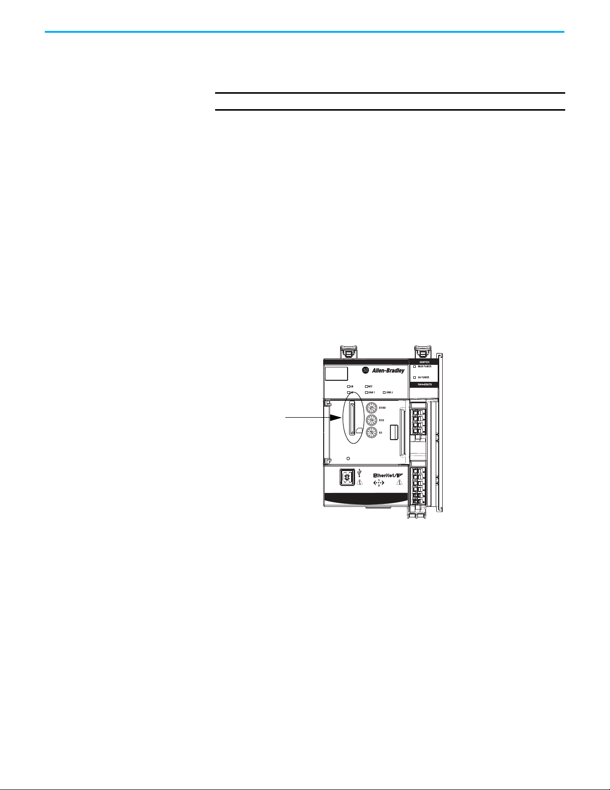
SD Card Slot
Secure Digital Card The 5069-AEN2TR EtherNet/IP adapter supports the use of a Secure Digital
(SD) card to store all configuration data that is stored in nonvolatile memory,
for example, the IP address or network communication rate for each port.
IMPORTANT
The 5069-AENTR adapter does not support the use of an SD card.
The adapter supports the use of a 1784-SD1 (1 GB) and 1784-SD2 (2 GB) card.
You can use third-party SD cards with the controller. You can use SD cards
with as much as 32 GB of memory. Keep in mind, Rockwell Automation does
not test the use of third-party SD cards with the controller.
If you use an SD card other than those cards that are available from
Rockwell Automation, unexpected results can occur. For example, you can
experience data corruption or data loss.
SD cards that are not provided by Rockwell Automation can have different
industrial, environmental, and certification ratings as those cards that are
available from Rockwell Automation. These cards can have difficulty with
survival in the same industrial environments as the industrially rated versions
available from Rockwell Automation.
An SD card slot is on the front of the adapter.
12 Rockwell Automation Publication 5069-UM007B-EN-P - January 2021
Page 13

Chapter 1 Compact 5000 EtherNet/IP Adapter Features
Adapter and SD Card Interaction
The 5069-AEN2TR adapter interacts with the SD card at power-up and when
the card is installed while the adapter is running.
IMPORTANT
No user action is required for the interaction between the adapter and the
SD card to occur.
Whenever configuration is written to the adapter, either at initial
configuration or when changes occur, it is written to the internal memory in
the adapter and the SD card.
The following apply regarding the adapter and SD card interacting:
Conditions Action That Occurs
• The adapter powers-up.
• The installed SD card does not contain adapter configuration data.
• The adapter powers-up.
• The installed SD card contains configuration data that differs from what is stored
on the internal memory.
• The adapter is running.
• You insert an SD card that contains configuration data that differs from what is
stored on the internal memory.
• The adapter is running.
• The adapter configuration changes.
The adapter firmware revision is updated.
The adapter configuration is copied from the internal memory to the SD card.
The configuration data on the SD card is copied to the internal memory and overwrites what
was previously there.
If the configuration data on the SD card includes an IP address that differs from what is on the
adapter, the overwrite changes the adapter IP address to match what is on the SD card.
There is no change to the configuration data in either the internal memory or the SD card.
A fault occurs and is indicated by the following:
•The message SD Data Mismatch scrolls across the adapter 4-character display.
• The S.MemoryCardDataMismatch tag changes to 1.
We recommend that you keep the data on the internal memory and SD card the same.
In this case, you can take one of the following actions to clear the fault and make sure the
configuration in the internal memory matches that on the SD card:
• If you want to use the configuration that is on the SD card, cycle power.
After power-up, the configuration data on the SD card is copied to the internal memory.
• If you want to use the configuration that is in the internal memory, change something in the
adapter configuration. The configuration data is updated in the internal memory and then
copied to the SD card.
Then change the configuration on the adapter back to its previous settings. The
configuration data is updated in the internal memory and then copied to the SD card.
The updated configuration data is copied from the internal memory to the SD card.
The adapter configuration data on the SD card is deleted before the update begins.
After the firmware revision is updated, the adapter configuration is copied from the internal
memory to the SD card.
Conformal Coating with 5069-AENTRK Adapter
The 5069-AENTRK EtherNet/IP adapter is conformal coated to add a layer of
protection when exposed to harsh, corrosive environments.
Rockwell Automation Publication 5069-UM007B-EN-P - January 2021 13
Page 14

Chapter 1 Compact 5000 EtherNet/IP Adapter Features
Notes:
14 Rockwell Automation Publication 5069-UM007B-EN-P - January 2021
Page 15

Compact 5000 EtherNet/IP Adapter Power
Requirements
This chapter explains how to power Compact 5000™ EtherNet/IP™ adapters.
Two Types of Power The adapters provide power to I/O modules as follows:
• MOD power - System-side power that powers the I/O modules and lets
them transfer data and execute logic.
System-side power is provided through the MOD Power connector and is
passed to each module as it is added to the system.
• SA power - Field-side power that powers some Compact 5000 I/O
modules and field-side devices that are connected to them.
Chapter 2
Field-side power is provided through the SA Power connector and is
passed to each module as it is added to the system.
Power begins at the adapter and passes across the I/O module internal
circuitry via power buses.
MOD power passes across a MOD power bus, and SA power passes across a SA
power bus. The MOD power bus and SA power bus are isolated from each
other.
IMPORTANT
For Compact 5000 EtherNet/IP adapter and I/O modules, we recommend
that you use a separate external power supply for the MOD power and SA
power, respectively.
If you use one external power supply and power is lost from that supply, the
system loses both MOD power and SA power. That is, system-side and field
side power, respectively, is lost.
If you use separate external power supplies, the loss of power from one
external power supply does not affect the availability of power from the
other supply. For example, if separate external power supplies are used and
SA power is lost, MOD power remains available for the Compact 5000 I/0
EtherNet/IP adapter and Compact 5000 I/0 modules.
Rockwell Automation Publication 5069-UM007B-EN-P - January 2021 15
Page 16
Chapter 2 Compact 5000 EtherNet/IP Adapter Power Requirements
Power RTB
MOD Power RTB
SA Power RTB
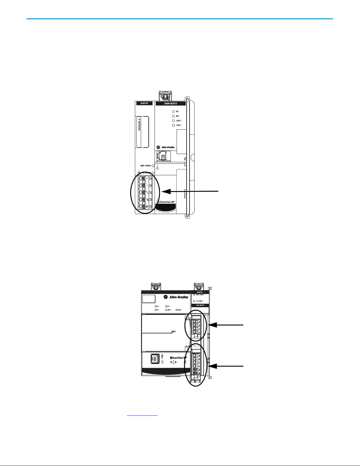
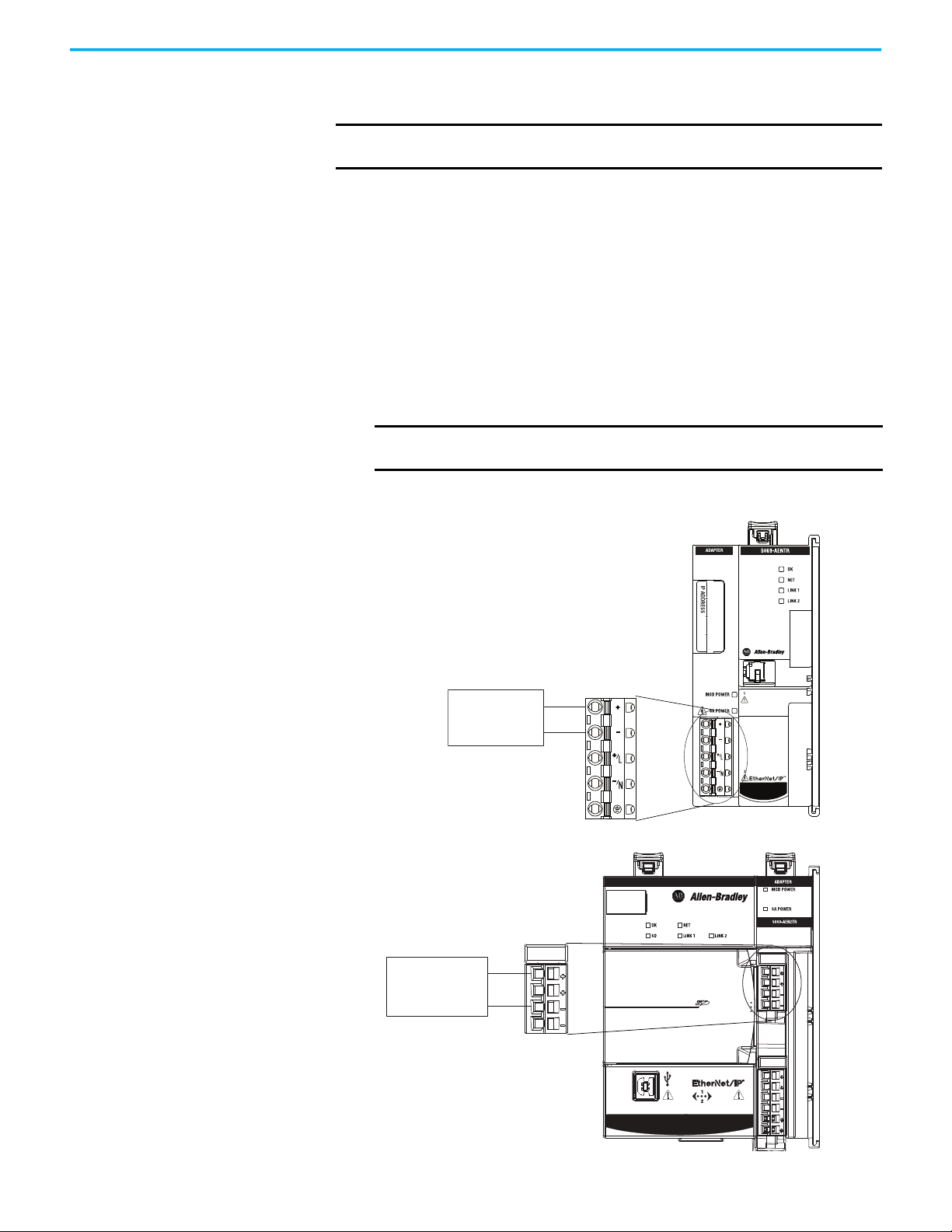
Power Connectors You connect external power supplies to removable terminal blocks (RTBs) to
provide MOD power and SA power. The adapters use different RTBs to connect
power.
The 5069-AENTR adapter uses a 5-terminal Power RTB to connect MOD power
and SA power. Both power types are provided to the system via one RTB.
Figure 2 - 5069-AENTR EtherNet/IP Adapter Power Connector
Compact 5000™ I/O
The 5069-AEN2TR adapter uses two RTBs to connect MOD power and SA
power. You connect an external power supply to the MOD power RTB to
provide MOD power. You connect an external power supply to the SA power
RTB to provide SA power.
Figure 3 - 5069-AEN2TR EtherNet/IP Adapter Power Connectors
MOD PowerSA Power
Compact 5000™ I/O
For more information on how to connect MOD power and SA power, see the
Compact 5000 I/0 EtherNet/IP Adapter Installation Instructions, publication
5069-IN003
16 Rockwell Automation Publication 5069-UM007B-EN-P - January 2021
.
Page 17
Chapter 2 Compact 5000 EtherNet/IP Adapter Power Requirements
Compact 5000™ I/O
24V DC
power supply
+
–
Compact 5000™ I/O
MOD PowerSA Power
24V DC
power supply
+
–
MOD Power Bus MOD power is a DC power source that is required to operate a Compact 5000
I/O system.
IMPORTANT You can only use DC power on the MOD power bus. Do not connect AC
power to the MOD power bus.
Remember the following:
• A Compact 5000 I/O system uses only one MOD power bus.
• Every module draws current from the MOD power bus and passes the
remaining current to the next module.
• You must limit the MOD power source to 10 A, max, at 18...32V DC.
• We recommend that you use an external power supply that is adequately
sized for the total MOD power bus current that is drawn by the adapters
and I/O modules.
For example, if the total MOD power current draw is 5 A, you can use a
MOD power supply that is limited to 5 A.
IMPORTANT
You must consider inrush current requirements when you
calculate the total MOD power bus current draw in the system.
Figure 4 - 5069-AENTR and 5069-AEN2TR EtherNet/IP Adapters MOD Power Connector
Rockwell Automation Publication 5069-UM007B-EN-P - January 2021 17
Page 18

Chapter 2 Compact 5000 EtherNet/IP Adapter Power Requirements
When the MOD power source is turned on, that is, I/O modules receive
system-side power, the following occurs.
1. The adapter draws current from the MOD power bus current and passes
the remaining current through to the next module.
2. The next module draws MOD power bus current and passes the
remaining current through to the next module.
3. The process continues until MOD power bus current needs are met for all
modules.
For more information on the current that the modules draw from the MOD
power bus, see the Compact 5000 I/O Modules Specifications Technical Data,
publication 5069-TD001
.
SA Power Bus SA power provides power to devices that are connected to some of the
Compact 5000 I/O modules. Remember the following:
• Some Compact 5000 I/O modules draw current from the SA power bus
and pass the remaining current to the next module.
• Some Compact 5000 I/O modules only pass current along the SA power
bus to the next module.
• A Compact 5000 I/O system can have multiple SA power buses. The first
SA power bus starts at the adapter and passes across the I/O modules
that are installed to the right of the adapter.
You use a 5069-FPD field potential distributor to establish a new SA
power bus. The new SA power bus is isolated from the SA power bus to its
left in the system.
For more information on how to use a 5069-FPD field potential
distributor in a CompactLogix™ 5380 system, see page 22
• You can connect either a 24V DC or 120/240V AC external power supply
to a 5069-FPD field potential distributor in a Compact 5000 I/O system.
• If AC and DC modules that require SA power are installed in a
Compact 5000 I/O system, you must use a 5069-FPD field potential
distributor to establish a new SA power bus.
You install one set of the same module types, for example, DC modules,
to the first SA power bus. Then you install the other set, for example, AC
modules to the second SA power bus. That is, the SA power bus to the
right of the 5069-FPD field potential distributor.
The SA power source limitations described previously apply to each
isolated SA power bus separately.
IMPORTANT
You must limit the SA power source to one of the following:
• If you use DC voltage, you must limit the SA power source to 10 A, max
at 18…32V DC.
• If you use AC voltage, you must limit the SA power source to 10 A, max
at 18…240V AC.
.
18 Rockwell Automation Publication 5069-UM007B-EN-P - January 2021
Page 19

Chapter 2 Compact 5000 EtherNet/IP Adapter Power Requirements
Compact 5000™ I/O
MOD PowerSA Power
Compact 5000™ I/O
AC or DC
power supply
+
–
AC or DC
power supply
+
–
• We recommend that you use an external power supply that is adequately
sized for the total SA power bus current draw.
For example, if the total SA power current draw is 4 A, you can use an SA
power supply that is limited to 4 A.
You must consider current inrush requirements when you calculate the
total SA power bus current draw.
• Connections to an SA power bus use a shared common. All inputs that
draw current from an SA power bus to power field-side devices have a
return through circuitry to the SA - terminal on the SA power connector.
IMPORTANT
Each SA power bus has a shared common unique to that bus
because SA power buses are isolated from each other.
That is, the SA power bus that the adapter establishes has a shared
common. If you use a 5069-FPD field potential distributor to establish
a new SA power bus in the system, the second bus has its own
shared common for modules that draw current from it.
Figure 5 - 5069-AENTR and 5069-AEN2TR EtherNet/IP Adapters SA Power Connector
Rockwell Automation Publication 5069-UM007B-EN-P - January 2021 19
Page 20

Chapter 2 Compact 5000 EtherNet/IP Adapter Power Requirements
When the SA power source is turned on, that is, the adapter and I/O modules
receive field-side power, the following occurs.
1. The Compact 5000 I/O EtherNet/IP adapter draws current from the SA
power bus current and passes the remaining current through to the next
module.
2. The next module completes one of the following tasks.
- If the module uses SA power to power a field-side device, the module
draws current from the SA power bus and passes the remaining
current through to the next module.
- If the module does not use SA power bus current, the module passes
the remaining current through to the next module.
3. The process continues until all SA power bus current needs are met for
the modules on the SA power bus.
For more information on the current that the Compact 5000 I/O modules draw
from the SA power bus, see the Compact 5000 I/O Modules Specifications
Technical Data, publication 5069-TD001
Track SA Power Bus Current Draw
.
We recommend that you track the SA power bus current draw, max, per
module, and collectively for the adapter and I/O modules in the system.
You must make sure that the Compact 5000 I/O modules that are installed on
an SA power bus do not consume more than 10 A. If so, you must establish
another SA power bus.
Consider the following with this example:
• The values in this example represent a worst-case calculation. That is, all
modules that draw SA power bus current, draw the maximum available
on the module.
• Not all modules that are shown in Figure 6
use SA power bus current. For
example, the 5069-ARM and 5069-OW4I modules only pass SA power bus
current to the next module.
Some other Compact 5000 I/O modules do not use SA power bus current,
but are not shown in the graphic, for example, the 5069-OB16 module.
20 Rockwell Automation Publication 5069-UM007B-EN-P - January 2021
Page 21

Chapter 2 Compact 5000 EtherNet/IP Adapter Power Requirements
Continuous MOD Power Bus Limited to 10 A, max
Continuous SA Power Bus Limited to 10 A, max
SA Power Bus Current, max,
Per Module
10 mA
System SA Power Bus Current, max = 1.222 A
128 mA 128 mA 128 mA 128 mA 0 mA 0 mA 100 mA 100 mA 250 mA 250 mA
• System SA power bus current, max, is calculated as each module draws
SA power bus current.
Compact 5000™ I/O
In the example in Figure 6
, after the 5069-IB16 module in slot 1 draws SA
power bus current, the system SA power bus current, max, is 138 mA.
After the 5069-IB16 module in slot 2 draws SA power bus current, the
system SA power bus current draw is 266 mA.
This process continues until the system SA power bus current, max,
is 1.222 A.
Figure 6 - Compact 5000 I/O EtherNet/IP Adapter and I/O Modules - Calculate SA Power Bus Current
Draw
ADDRESS RESERVE
DC INPUT
DC INPUT
DC INPUT
5069-IB16
5069-IB16
5069-IB16F
MOD PowerSA Power
DC INPUT
5069-IB16F
RELAY OUTPUT
5069-OW4I
5069-ARM
ANALOG INPUT
5069-IY4
ANALOG INPUT
5069-IY4
ANALOG OUTPUT
5069-OF8
ANALOG OUTPUT
5069-OF8
Rockwell Automation Publication 5069-UM007B-EN-P - January 2021 21
Page 22

Chapter 2 Compact 5000 EtherNet/IP Adapter Power Requirements
AC or DC
power supply
+
–
Use a 5069-FPD Field Potential Distributor to Create a New SA Power Bus
You can use a 5069-FPD field potential distributor to add an SA power bus to a
Compact 5000 I/O system; this changes the field-side power distribution
source for Compact 5000 I/O modules. However, the field potential distributor
passes MOD power bus signals through to the next module in the system.
The field potential distributor blocks the current that passes across the SA
power bus to its left. At that point, the field potential distributor establishes a
new SA power bus for modules to the right. The new SA power bus is isolated
from the SA power bus to its left in the system.
You can connect either a 24V DC or 120/240V AC external power supply to a
5069-FPD field potential distributor.
Figure 7 - 5069-FPD Field Potential Distributor SA Power Connector
FIELD POWER
5069-FPD
The SA power bus that a field potential distributor establishes functions in the
same way as the SA power bus that a Compact 5000 EtherNet/IP adapter
establishes functions.
Examples of system configurations that use multiple SA power buses include:
• The modules in the system collectively draw more than 10 A of SA power.
That is, the maximum current that one SA power bus can provide.
• The modules in the system are of different module types, that is, AC
voltage and DC voltage.
22 Rockwell Automation Publication 5069-UM007B-EN-P - January 2021
Page 23

Chapter 2 Compact 5000 EtherNet/IP Adapter Power Requirements
Continuous MOD Power Bus Limited to 10 A, max
SA Power Bus Limited to 10 A, max
SA Power Bus Limited to 10 A, max
5069-FPD Field Potential Distributor
DC Type I/O Modules AC Type I/O Modules
In this example, a 5069-FPD
field potential distributor is
used to create an SA power
bus so the DC type I/O modules
are separated from the AC type
I/O modules.
Figure 8 show examples when a 5069-FPD field potential distributor creates a
second SA power bus.
Figure 8 - Compact 5000 I/O EtherNet/IP Adapter and I/O Modules - Create a New SA Power Bus
DC OUTPUT
DC OUTPUT
DC INPUT
DC INPUT
FIELD POWER
5069-FPD
Compact 5000™ I/O
5069-IB16
5069-IB16
5069-OB16
5069-OB16
SA Power - Additional Notes
Remember the following:
• We recommend that you use a separate power supply for the SA power
connection from the power supply that is used with the MOD power
connection.
• The actual current in a Compact 5000 I/O system SA power bus current
draw changes based on the operating conditions at a given time.
For example, the SA power bus current draw on some modules is
different if all channels power field devices or half of the channels power
field devices.
• Not all Compact 5000 I/O modules use SA power.
For example, the 5069-ARM, 5069-OB16, 5069-OB16F, 5069-OW4I, and
5069-OX4I modules do not use SA power.
• Some Compact 5000 I/O modules use field-side power but do not draw it
from a SA power bus. The modules receive field-side power from an
external power supply that is connected to the module RTB.
For example, the 5069-OB16 and 5069-OB16F modules use Local Actuator
(LA) terminals, that is, LA+ and LA- terminals for all module channels.
Rockwell Automation Publication 5069-UM007B-EN-P - January 2021 23
Page 24

Chapter 2 Compact 5000 EtherNet/IP Adapter Power Requirements
Compact 5000™ I/O
MOD Power
SA Power Bus - From
SELV-listed Power Supply
+
–
24V DC
Power Supply
+
–
Compact 5000 I/O 24V DC safety and
standard input module
Ground
SA Power Bus - From
Standard Power Supply
120/240V AC
Standard Power
Supply
+
–
Ground
Compact 5000 I/O 120/240V AC
standard input modules
Compact 5000 I/O 24V DC relay modules
24V DC Power
Supply
+
–
Ground
SA Power Bus - From
Standard Power Supply
24V DC
SELV-listed
Power Supply
Restrictions When You Install Compact 5000 I/O Safety Modules in a Compact 5000 I/O System
You can install Compact 5000 I/O safety modules in a Compact 5000 I/O
system. Table 2
safety modules in a remote system.
Table 2 - Restrictions - Compact 5000 I/O Safety Modules in a Compact 5000 I/O System
describes restrictions that you must meet when you use the
Component to Which SA
Power Is Connected
5069-FPD Field Potential
Distributor
With Compact 5000 I/O
Safety and Standard
Modules
Restrictions
The following restrictions apply:
• You can use non-SELV or PELV power supplies if only Compact 5000 I/O standard modules are installed to the right of the 5069-FPD field
potential distributor.
• The power supply that provides SA power to the Compact 5000 I/O safety modules must be SELV/PELV-listed.
• If Compact 5000 I/O relay modules are installed before the Compact 5000 I/O safety modules, you must install a 5069-FPD field potential
distributor before the safety modules. This creates additional isolation. In this case, you must use a SELV/PELV-listed supply with the 5069-FPD
field potential distributor.
• If AC modules are added before the Compact 5000 I/O safety modules, you must install a 5069-FPD field potential distributor that is powered by
an SELV/PELV-listed power supply, before the safety modules.
Example Compact 5000 I/O System
24 Rockwell Automation Publication 5069-UM007B-EN-P - January 2021
Page 25

Chapter 2 Compact 5000 EtherNet/IP Adapter Power Requirements
MOD Power
SA Power Bus - From
SELV-listed Power Supply
+
–
24V DC
Power Supply
+
–
Compact 5000 I/O 24V DC safety and
standard input module
Ground
SA Power Bus - From
Standard Power Supply
120/240V AC
Standard Power
Supply
+
–
Ground
Compact 5000 I/O 120/240V AC
standard input module
SA Power Bus - From
SELV-listed Power Supply
24V DC
SELV-listed
Power Supply
+
–
Ground
Compact 5000 I/O 24V DC safety and
standard output module
24V DC
SELV-listed
Power Supply
Table 2 - Restrictions - Compact 5000 I/O Safety Modules in a Compact 5000 I/O System
Component to Which SA
Power Is Connected
5069-FPD Field Potential
stributor
Di
With Compact 5000 I/O
Safety and Standard
Modules
Restrictions
In addition to the restrictions on page 24
, this restriction also applies:
• You must use SELV or PELV power supplies to provide SA power to Compact 5000 I/O safety modules that are installed to the right of the 5069FPD field potential distributor.
Example Compact 5000 I/O System
Compact 5000™ I/O
Rockwell Automation Publication 5069-UM007B-EN-P - January 2021 25
Page 26

Chapter 2 Compact 5000 EtherNet/IP Adapter Power Requirements
Notes:
26 Rockwell Automation Publication 5069-UM007B-EN-P - January 2021
Page 27

Chapter 3
Connect to the EtherNet/IP Network
You must set the IP address on the adapter for the adapter to operate on an
EtherNet/IP™ network.
The following are adapter conditions in which you set the IP address:
• Set the IP address for the first time after it powers up in the
out-of-box state.
IMPORTANT
• Change the IP address after it has been set.
The adapter powers up in the out-of-box the first time you install it.
However, the adapter also after power is cycled and the adapter is
configured to clear its IP address after power is cycled.
Set the IP Address When the adapter is in the out-of-the-box state, the following apply regarding
IP addresses:
• The adapters ship without an IP address.
• The rotary switches on the adapter are set as follows:
- 5069-AENTR adapter - 999
- 5069-AEN2TR adapter - 000
• The adapter is DHCP-enabled. That is, the adapter is configured to
obtain an IP address via a DHCP server.
If there is no DHCP server or the DHCP server is not configured to set
the IP address, you must set the IP address manually.
• The adapter issues requests for an IP address via DHCP until an IP
address is set by using one of the tools that are described in this section.
• The adapter is configured so that you must set the IP address each time
that power is cycled.
You can change the adapter configuration so that you are not required to
set an IP address each time that power is cycled.
Requirements
To set the IP address, have the following:
• EtherNet/IP or USB drivers that are installed on the programming
workstation (For more information on setting drivers or IP addresses,
see ENET-UM006
• MAC ID from the device, which is on the label on the side of the device
• Recommended IP address for the device
Rockwell Automation Publication 5069-UM007B-EN-P - January 2021 27
)
Page 28

Chapter 3 Connect to the EtherNet/IP Network
Rotary switches
are on the side of
the adapter.
MOD Power
Rotary switches
are on the front of
the adapter.
Set the IP Address with the Rotary Switches
If the network uses 192.168.1.x, use the rotary switches on the adapter to set the
last octet of network IP address. Valid numbers range from 001…254.
IMPORTANT
The rotary switches only set the IP address when power is cycled.
WARNING: When you change switch settings on the adapter while power is on, an
electric arc can occur. This arc could cause an explosion in hazardous location
installations. Be sure that power is removed or the area is nonhazardous before
proceeding.
When you press the reset button on the 5069-AEN2TR adapter while power is
on, an electric arc can occur. This arc could cause an explosion in hazardous
location installations. Be sure that power is removed or the area is
nonhazardous before proceeding.
IMPORTANT The 5069-AENTR adapter does not have a reset button.
• 5069-AENTR - The leftmost switch represents the first digit in the octet,
the middle switch represents the second digit, and the right-most switch
represents the third digit.
• 5069-AEN2TR - The bottom switch represents the first digit in the octet,
the middle switch represents the second digit, and the top switch
represents the third digit.
28 Rockwell Automation Publication 5069-UM007B-EN-P - January 2021
Page 29

Chapter 3 Connect to the EtherNet/IP Network
Other Methods to Set the IP Address
Reset the 5069-AENTR Adapter
The Compact 5000 EtherNet/IP™ adapter supports the following additional
methods to change the IP address:
• BOOTP/DHCP utility
• RSLinx® Classic software
• For more information on how to use these methods, see EtherNet/IP
Network Device User Manual, publication ENET-UM006
You can reset the adapters to their factory default values. There are differences
in the required tasks to reset the adapters.
To reset the adapter to its default settings, complete the following steps.
1. Power down the adapter.
2. Set the rotary switches to 888.
3. Power up the adapter.
4. Wait for the adapter power-up sequence to complete.
The power-up sequence is complete, and the adapter has returned to its
factory default setting when the status indicator states are as follows:
- OK indicator - Flashing red
- All other indicators - Alternate between red and green
5. Power down the adapter.
6. Set the rotary switches to the desired address.
.
IMPORTANT
7. Power up the adapter.
If you do not want to set the IP address via the rotary switches, set
them to 999.
After the adapter powers up, set the IP address.
Rockwell Automation Publication 5069-UM007B-EN-P - January 2021 29
Page 30

Chapter 3 Connect to the EtherNet/IP Network
Reset Button
Reset the 5069-AEN2TR Adapter
You can reset the 5069-AEN2TR adapter to its factory default values with the
reset button.
ATTENTION: When you reset a module, all connections to or through the
module are closed, and can result in loss of control.
WARNING: When you press the reset button while power is on, an electric arc can
occur. This arc could cause an explosion in hazardous location installations. Be
sure that power is removed or the area is nonhazardous before proceeding.
1. Power down the adapter.
2. Open the front door on the adapter.
3. Use a small tool or screwdriver to press and hold the reset button.
4. While holding in the reset button, power up the adapter.
5. Continue to hold the reset button while the 4-character display cycles
through TEST, DFLT, 4, 3, 2, 1.
6. Factory Default scrolls one time across the display.
7. Release the reset button.
MOD PowerSA Power
Compact 5000™ I/O
30 Rockwell Automation Publication 5069-UM007B-EN-P - January 2021
Page 31

Chapter 4
Configure the Adapter
After you install the communication module and set the IP address, you must
add the module to a controller project. The project must be online to set the
Speed and Duplex configurable parameters on the module.
IMPORTANT
You can use the Logix Designer application, version 28.00.00 or later, with
Compact 5000™ EtherNet/IP™ adapters.
Depending on what version of Logix Designer application that your
application uses, you can be required to install an Add-on Profile (AOP).
AOPs are made available between releases of different Logix Designer
application versions. By obtaining and installing an AOP, you can add the
adapter to your project.
You can access AOPs from the Product Compatibility and Download Center
(PCDC) that is available at:
https://compatibility.rockwellautomation.com/Pages/home.aspx
Add the Module to a Project 1. Verify that your project is offline.
2. Right-click your network port, and choose New Module.
Rockwell Automation Publication 5069-UM007B-EN-P - January 2021 31
Page 32

Chapter 4 Configure the Adapter
3. On the Select Module Type dialog box, complete the following tasks:
a. In the search field, type the catalog number for your adapter.
This example uses the 5069-AEN2TR adapter.
b. In the Catalog Number field, select the adapter.
For some modules, the Select Major Revision dialog box can appear. If
the dialog box appears, choose the major revision of the module and click
OK.
c. Click Create.
4. On the New Module dialog box, complete the following tasks on the
General category page:
a. Type a name.
b. Enter the IP address.
c. In the Module Definition area, click Change.
32 Rockwell Automation Publication 5069-UM007B-EN-P - January 2021
Page 33

Chapter 4 Configure the Adapter
The Module Definition dialog box appears.
5. Complete the following tasks.
a. Set the appropriate Revision of the firmware that is on your adapter.
This field only displays the major revisions that are applicable to
Major Revision (left pull-down menu)
Minor Revision (right field)
the selected series. This field appears dimmed when online
unless the module supports allowing major revision changes to
be made while online.
Sets the minor revision of the module. The valid range is 1…255.
This field is enabled while offline, and while in the Program,
Remote Program, and Remote Run modes. It appears dimmed
when in Run mode, or when electronic keying is set to Disable
Keying
b. Select the appropriate the Electronic Keying setting.
Electronic Keying is enabled while offline, and while in Program,
Remote Program, and Remote Run modes. It appears dimmed when
in Run mode.
Electronic Keying reduces the possibility that you use the wrong device
in a control system. It compares the device that is defined in your
project to the installed device. If keying fails, a fault occurs. The
following attributes are compared.
Attribute Description
Vendor The device manufacturer.
Device Type The general type of the product, for example, digital I/O module.
Product Code The specific type of the product. The Product Code maps to a catalog number.
Major Revision A number that represents the functional capabilities of a device.
Minor Revision A number that represents behavior changes in the device.
Rockwell Automation Publication 5069-UM007B-EN-P - January 2021 33
Page 34

Chapter 4 Configure the Adapter
The following Electronic Keying options are available.
Keying Option Description
Lets the installed device accept the key of the device that is defined in the project
when the installed device can emulate the defined device. With Compatible Module, you
can typically replace a device with another device that has the following
characteristics:
Compatible Module
Disable Keying
Exact Match
• Same catalog number
• Same or higher Major Revision
• Minor Revision as follows:
– If the Major Revision is the same, the Minor Revision must be the same or higher.
– If the Major Revision is higher, the Minor Revision can be any number.
Indicates that the keying attributes are not considered when attempting to
communicate with a device. With Disable Keying, communication can occur with a
device other than the type specified in the project.
ATTENTION: Be cautious when you use Disable Keying; if used incorrectly, this option
can lead to personal injury or death, property damage, or economic loss.
We strongly recommend that you do not use Disable Keying.
If you use Disable Keying, you must take full responsibility for understanding whether
the device being used can fulfill the functional requirements of the application.
Indicates that all keying attributes must match to establish communication. If any
attribute does not match precisely, communication with the device does not occur.
Carefully consider the implications of each keying option when
selecting one.
IMPORTANT
When you change Electronic Keying parameters online, it
interrupts connections to the device and any devices that are
connected through the device. Also, connections from other
controllers can be broken.
If an I/O connection to a device is interrupted, the result can be a
loss of data.
For more detailed information on Electronic Keying, see Electronic
Keying in Logix 5000™ Control Systems Application Technique,
publication LOGIX-AT001
.
c. Select the Connection.
None No direct connection from Controller (Originator) to the adapter.
Status Reports device status.
d. Set the Chassis Size to the number of modules including the adapter.
For example, one adapter with nine I/O modules equals a chassis size of
ten.
e. Click OK.
34 Rockwell Automation Publication 5069-UM007B-EN-P - January 2021
Page 35

Chapter 4 Configure the Adapter
If you set the Connection to Status, click Yes on the Logix 5000™
dialog box.
6. On the New Module dialog box, click the Connection category and
complete the tasks:
a. Set the Requested Packet Interval (RPI). The range is 25…750 ms, with
100 ms as the default. This connection is for status data only, with
no I/O.
b. Select the Connection over EtherNet/IP, Unicast, or Multicast.
For non-redundant controllers, the default value is Unicast when the
target device supports unicast; otherwise, the default value is Multicast.
For redundant controllers, the default value is Multicast when the target
device supports multicast; otherwise, the default value is Unicast.
c. Click OK.
7. Save the project.
8. If the project does not have a communication path to the controller, click
Browse to create a path.
Rockwell Automation Publication 5069-UM007B-EN-P - January 2021 35
Page 36

Chapter 4 Configure the Adapter
9. On the Who Active dialog box, choose the desired path and click Set
Project Path and close the dialog box.
10. Verify that the controller mode switch is in the PROG mode position
11. Click the Controller Status icon, and choose Go Online.
36 Rockwell Automation Publication 5069-UM007B-EN-P - January 2021
Page 37

Chapter 4 Configure the Adapter
12. On the Connected To Go Online dialog box, click Download.
13. On the Download dialog box, click Download.
Rockwell Automation Publication 5069-UM007B-EN-P - January 2021 37
Page 38

Chapter 4 Configure the Adapter
14. Confirm that you want to download the project.
The project downloads to the controller. The dialog box closes when
the download is complete.
15. If you did not already configure the Ethernet port speed and duplex
settings with RSLinx® Classic software, complete the following tasks.
a. Put the controller mode switch in the REM position.
b. Change the Logix Designer application project to Run mode.
.
38 Rockwell Automation Publication 5069-UM007B-EN-P - January 2021
Page 39

Chapter 4 Configure the Adapter
c. When prompted to Change controller mode to Remote Run, click Yes.
d. Right-click the adapter, and choose Properties.
e. On the Module Properties dialog box, click the Port
Configuration category.
Desired Task Action
Let the module automatically set the
port speed and duplex settings.
Manually configure your port speed
and duplex settings.
IMPORTANT
Consider the following when you configure the port settings:
Leave Auto-negotiate enabled.
Complete the following steps.
1. Clear the Auto-negotiate port speed and duplex checkbox.
2. From the Current Port Speed pull-down menu, choose a port
speed.
3. From the Current Duplex pull-down menu, choose full-duplex.
• The Compact 5000 I/O EtherNet/IP adapters only support
full-duplex mode.
• The speed and duplex settings for the devices on the same
Ethernet network must be the same to avoid transmission errors.
• Fixed speed and full-duplex settings offer better reliability than
autonegotiate settings and are recommended for some
applications.
• If the module is connected to an unmanaged switch, leave Autonegotiate checked or the module fails.
• If you force the port speed and duplex with a managed switch, the
corresponding port of the managed switch must be forced to the
same settings or the module fails.
• If you connect a manually configured device to an autonegotiate
device (duplex mismatch), a high rate of transmission errors can
occur.
Rockwell Automation Publication 5069-UM007B-EN-P - January 2021 39
Page 40

Chapter 4 Configure the Adapter
16. Click the Internet Protocol category.
If needed, you can set Internet Protocol properties such as:
•Domain Name
•Host Name
• Gateway Address
• Primary and secondary DNS Server Addresses.
f. On the Module Properties dialog box, click OK.
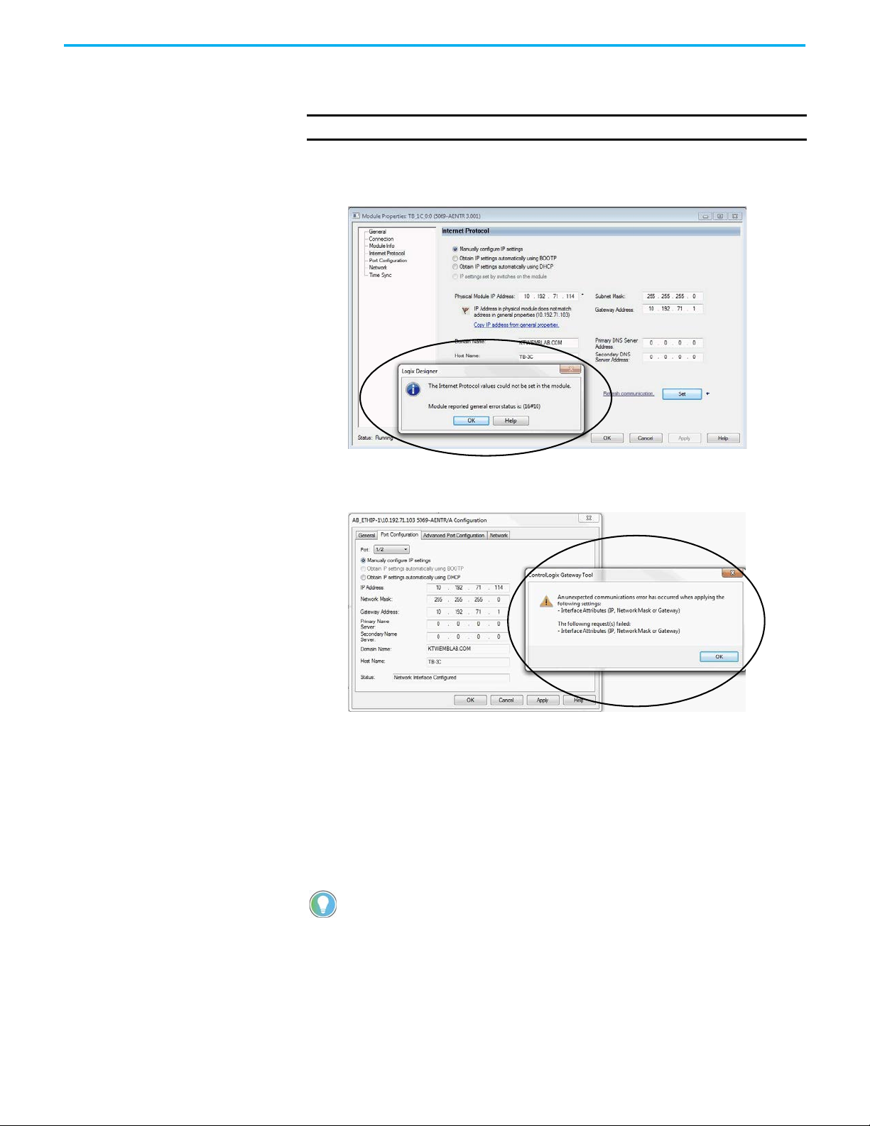
IMPORTANT
If you try to change the IP address on this page, the following alert
appears:
g. Save the project.
40 Rockwell Automation Publication 5069-UM007B-EN-P - January 2021
Page 41

Chapter 4 Configure the Adapter
Enable or Disable HTTP Server and SNMP Server
You can enable or disable the HTTP server and SNMP server as an added
security feature from firmware revision 4.011 or later. The HTTP server and
SNMP server are disabled by default from firmware revision 4.011 or later.
Disabling these servers in conjunction with using the Explicit Protected Mode
decreases the possibility of a security breach.
Enable the HTTP Server in Logix Designer Application
To change the settings in the Add-on Profile Server pages, make sure that the
adapter is not in Explicit Protected Mode. To exit Explicit Protected Mode, see
Enter and Exit Explicit Protected Mode on page 9
IMPORTANT From firmware revision 4.011 or later, the HTTP server is disabled by default
in out of box state and after performing a factory reset.
1. In the Logix Designer application project, select the adapter device from
the Controller Organizer pane.
2. Right-click the adapter, and choose Properties.
.
Rockwell Automation Publication 5069-UM007B-EN-P - January 2021 41
Page 42

Chapter 4 Configure the Adapter
3. On the Module Properties page, click Servers in the tree view.
4. Select the Enable checkbox next to the Hypertext Transfer Protocol
(HTTP) server.
You can select the checkbox only when the controller is online.
5. Click the Apply button to accept the changes. You do not need to cycle
power to the adapter.
6. Enter Explicit Protected Mode.
ATTENTION: To decrease the possibility of a security breach, use Explicit
Protected Mode and do not enable the HTTP server.
42 Rockwell Automation Publication 5069-UM007B-EN-P - January 2021
Page 43

Chapter 4 Configure the Adapter
Enable the SNMP Server in Logix Designer Application
To change the settings in the Add-on Profile Server pages, make sure that the
adapter is not in Explicit Protected Mode. To exit Explicit Protected Mode, see
Enter and Exit Explicit Protected Mode on page 9
1. In the Logix Designer application project, select the adapter device from
the Controller Organizer pane.
2. Right-click on the adapter and select Properties from the menu.
.
3. On the Module Properties page, click Servers in the tree view.
4. Select the Enable checkbox next to the Simple Network Management
Protocol (SNMP) server.
The controller must be online to select the checkbox. If the controller is
offline, you cannot select the checkbox.
5. Click the Apply button to accept the changes. You do not need to cycle
power to the adapter.
6. Enter Explicit Protected Mode.
ATTENTION: To decrease the possibility of a security breach, use Explicit
Protected Mode and do not enable the SNMP server.
Rockwell Automation Publication 5069-UM007B-EN-P - January 2021 43
Page 44

Chapter 4 Configure the Adapter
Notes:
44 Rockwell Automation Publication 5069-UM007B-EN-P - January 2021
Page 45

Appendix A
Power Status Indicators
Controller and EtherNet/IP
Status Indicators
Compact 5000 EtherNet/IP Adapter
Status Indicators
EtherNet/IP™ communication modules have multi-character displays and
status indicators to assist with performance and diagnostics.
5069-AENTR Adapter Status Indicators
Figure 9 - 5069-AENTR Adapter Status Indicators
Table 3 describes the 5069-AENTR adapter status indicators.
Table 3 - 5069-AENTR Status Indicators
Indicator State Description Recommended Action
Off There is no power applied to the device. Apply power as necessary
Flashing Green The IP address is not set. Set the IP address using one of the recommended methods.
Steady green The device is operating in a normal condition. None
One of the following:
OK
Flashing red
Steady red The device has an unrecoverable fault. Cycle power. If the fault persists, replace the device.
• The device has a recoverable fault. The fault can be read from the
diagnostic webpages.
• A firmware update is being performed on the device.
• The adapter has powered up and is in the Factory Default state.
In this case, all other indicators flash red and green.
Rockwell Automation Publication 5069-UM007B-EN-P - January 2021 45
One of the following:
• Cycle power.
• Wait for the firmware update to finish.
• Use adapter as necessary.
Page 46

Appendix A Compact 5000 EtherNet/IP Adapter Status Indicators
Table 3 - 5069-AENTR Status Indicators
Indicator State Description Recommended Action
Off
Flashing green
Steady green
NET
Steady red There is a Duplicate IP address condition or invalid configuration.
Flashing red and
green
Off
LINK1
Flashing green Activity exists on the port. None
Flashing red and
green
Off
LINK2
Flashing green Activity exists on the port. None
Steady green Adapter is the supervisor of a Device Level Ring network. None
Flashing red and
green
Off There is no module power applied to the device. Apply MOD power as necessary
Steady green Module power is present. None
MOD Power
Flashing red and
green
Off Status of SA power is unknown. Apply SA power as necessary
Steady green SA power is present. None
SA Power
Flashing red and
green
The device is not configured, or does not have an IP address. Configure the device or assign an IP address.
The device has an IP address, but no active connections are
established.
The device has an IP address and at least one established active
connection.
The device has powered up and is in the Factory Default state.
In this case, the OK indicator is flashing red and all other indicators
flash red and green.
No activity. One of the following conditions exists:
• The module is not powered.
• The RJ45 cables are properly seated in the adapter and connected
devices.
• No link exists on the port.
• The port is administratively disabled.
• The port is disabled due to rapid ring faults.
• The port configuration is configured in a manner that can result in
issues. For example, the port can be configured to Autonegotiate
and the port at the other end of the cable is configured such that
Autonegotiate is disabled.
The device has powered up and is in the Factory Default state.
In this case, the OK indicator is flashing red and all other indicators
flash red and green.
The de
vice has powered up and is in the Factory Default state.
In this case, the OK indicator is flashing red and all other indicators
flash red and green.
The device has powered up and is in the Factory Default state.
In this case, the OK indicator is flashing red and all other indicators
flash red and green.
Establish connections as required by the project.
None
Troubleshoot the issue and remedy the cause.
For example, if a Duplicate IP address condition exists, determine
which devices on the network use the same IP address and change
the IP addresses to unique values.
Use adapter as necessary.
One of the following:
• If there is no power to the device, complete one of the following:
– Turn on power.
– Verify that the module RTB is properly seated in the adapter.
IMPORTANT: Before you touch the module RTB, verify that power
is not applied to the adapter. Once the module RTB is properly
seated, turn on power.
• Verify that the RJ45 cables are properly seated in the adapter and
connected devices.
• If there is power to the device but no link exists, troubleshoot the
issue and remedy the cause.
• If the port is administratively disabled, confirm that is the desired
state. If not, use RSLinx® Classic software or the Logix Designer
application to enable the port.
Use adapter as necessary.
One of the following:
• If there is no power to the device, complete one of the following:
– Turn on power.
– Verify that the module RTB is properly seated in the adapter.
IMPORTANT: Before you touch the module RTB, verify that power
is not applied to the adapter. Once the module RTB is properly
seated, turn on power.
• Verify that the RJ45 cables are properly seated in the adapter and
connected devices.
• If there is power to the device but no link exists, troubleshoot the
issue and remedy the cause.
• If the port is administratively disabled, confirm that is the desired
state. If not, use RSLinx Classic software or the Logix Designer
application to enable the port.
• If the port is disabled due to rapid ring faults, troubleshoot the
cause of the fault and remedy it.
• Check configuration for the links at both ends of the cable and
verify that they are correct to perform normal operation.
Use adapter as necessary.
Use adapter as necessary.
Use adapter as necessary.
46 Rockwell Automation Publication 5069-UM007B-EN-P - January 2021
Page 47

Appendix A Compact 5000 EtherNet/IP Adapter Status Indicators
MOD Power
Power Status Indicators
Controller Status Indicators
EtherNet/IP Status Indicators
4-character Scrolling
Status Display
5069-AEN2TR Adapter Status Indicators
Table 4 - 5069-AEN2TR Status Indicators
Figure 10 - 5069-AEN2TR Adapter Status Indicators
Table 4 describes the 5069-AEN2TR adapter status indicators.
Indicator State Description Recommended Action
Off There is no power applied to the device. Apply power as necessary
Steady green The device is operating in a normal condition. None
OK
SD
NET
LINK1
One of the following:
Flashing red
Steady red The device has an unrecoverable fault. Cycle power. If the fault persists, replace the device.
Off There is no activity to the SD card. None
Flashing green The controller is reading from, or writing to the SD card. None
Steady red The SD card does not have a valid file system. None
Off The device is not configured, or does not have an IP address. Configure the device or assign an IP address.
Flashing green
Steady green
Steady red There is a Duplicate IP address condition or invalid configuration.
Off
Flashing green Activity exists on the port. None
• The device has a recoverable fault. The fault can be read from the
device through the USB or Ethernet ports.
• A firmware update is being performed on the device.
The device has an IP address, but no active connections are
established.
The device has an IP address and at least one established active
connection.
No activity. One of the following conditions exists:
• The module is not powered.
• The RJ45 cables are properly seated in the adapter and connected
devices.
• No link exists on the port.
One of the following:
• Cycle power.
• Wait for the firmware update to finish.
Establish connections as required by the project.
None
Troubleshoot the issue and remedy the cause.
For example, if a Duplicate IP address condition exists, determine
which devices on the network use the same IP address and change
the IP addresses to unique values.
One of the following:
• If there is no power to the device, complete one of the following:
– Turn on power.
– Verify that the module RTB is properly seated in the adapter.
• Verify that the RJ45 cables are properly seated in the adapter and
connected devices.
• If there is power to the device but no link exists, troubleshoot the
issue and remedy the cause.
IMPORTANT: Before you touch the module RTB, verify that power
is not applied to the adapter. Once the module RTB is properly
seated, turn on power.
Rockwell Automation Publication 5069-UM007B-EN-P - January 2021 47
Page 48

Appendix A Compact 5000 EtherNet/IP Adapter Status Indicators
Table 4 - 5069-AEN2TR Status Indicators
Indicator State Description Recommended Action
One of the following:
• If there is no power to the device, complete one of the following:
– Turn on power.
– Verify that the module RTB is properly seated in the adapter.
IMPORTANT: Before you touch the module RTB, verify that power
is not applied to the adapter. Once the module RTB is properly
seated, turn on power.
• Verify that the RJ45 cables are properly seated in the adapter and
connected devices.
• If there is power to the device but no link exists, troubleshoot the
issue and remedy the cause.
• If the port is administratively disabled, confirm that is the desired
state.
• If the port is disabled due to rapid ring faults, troubleshoot the
cause of the fault and remedy it.
LINK2
MOD Power
SA Power
No activity. One of the following conditions exists:
• The module is not powered.
• The RJ45 cables are properly seated in the adapter and connected
Off
Flashing green Activity exists on the port. None
Steady green Adapter is the supervisor of a Device Level Ring network. None
Off There is no module power applied to the device. Apply MOD power as necessary
Steady green Module power is present. None
Off Status of SA power is unknown. Apply SA power as necessary
Steady green SA power is present. None
devices.
• No link exists on the port.
• The port is administratively disabled.
• The port is disabled due to rapid ring faults.
Table 5 describe the possible messages on the 4-character display for a
5069-AEN2TR adapter.
Table 5 - Messages on 4-character Display
Message Type Example Message on 4-character Display Description
TEST TEST Message appears while power-up tests run.
PASS PASS Message appears when power-up tests complete.
Embedded software version Rev 2.003
OK OK
Port Down Link 2 - Port Down
Port Rate/Duplex State Port 1 - 1Gb/FULL
IP Address 192 .168.1.17
Link Disabled Port 2 - Link Disabled
Duplicate IP Duplicate IP - 00:00:BC:02:34:B4
Fault Cycle power to unit. Message appears, and scrolls continuously, during a fault.
Message appears once, after the power-up tests complete
successfully.
The first message in the scrolling message display. Message scrolls
continuously during operation.
Message appears when an EtherNet/IP port does not have a
connection. Message scrolls continuously during operation.
The current port rate and duplex state. Message scrolls continuously
during operation. If not connected to a 1 Gb switch, the message
shows 100/FULL.
The IP address of the adapter. Message scrolls continuously during
operation.
Message appears when you have disabled an EtherNet/IP port.
Message scrolls continuously during operation.
Message appears when the adapter detects a device with the same IP
address on the network. The message shows the MAC ID of the device
with the duplicate IP address. Message scrolls continuously during
operation.
48 Rockwell Automation Publication 5069-UM007B-EN-P - January 2021
Page 49

Appendix B
Module Tags
Module tags are created when you add the adapter to a controller project and
set the connection to Status.
Compact 5000 EtherNet/IP
Figure 6 describes the Compact 5000™ EtherNet/IP™ adapter tags:
Adapter Tags
Table 6 - Compact 5000 I/O EtherNet/IP Adapter Module Tags
Tag Name Data Type Definition Valid Values
RunMode BOOL Module operating state
ConnectionFaulted BOOL
DiagnosticActive BOOL Indicates if any diagnostics are active or if the prognostics threshold is reached.
CIPSyncValid BOOL Indicates if the module is synced with a 1588 master.
CIPSyncTimeout BOOL
DiagnosticSequenceCount SINT
OverTemperature BOOL
CriticalTemperature BOOL
Port1Connected BOOL Indicates if the numbered Ethernet port is active.
Port2Connected BOOL Indicates if the numbered Ethernet port is active.
Port1FullDuplex BOOL
Port2FullDuplex BOOL
Indicates if a connection to the target is running.
The module always returns a zero in this member. The controller overwrites the
zero with a one when the connection is not up.
Indicates if the module was once synced with a 1588 master, but is not now due to
a timeout.
Increments for each time a distinct diagnostic condition is detected, and when a
distinct diagnostic condition transitions from detected to not detected.
Set to zero by product reset or power cycle. Wraps from 255 (-1) to 1 skipping zero.
Indicates if the module is at its maximum thermal rating.
IMPORTANT: This tag is always 0 with the 5069-AENTR adapter.
Indicates if the temperature is approaching (but below) the point of thermal
runaway.
IMPORTANT: This tag is always 0 with the 5069-AENTR adapter.
Indicates if the numbered Ethernet port, if it is connected, is running full-duplex
mode or half-duplex mode.
Indicates if the numbered Ethernet port, if it is connected, is running full-duplex
mode or half-duplex mode.
•0 = Idle
•1 = Run
• 0 = Connection running
• 1 = Connection not running
• 0 = No diagnostics active
• 1 = One or more diagnostics are active or the
prognostics threshold is reached
• 0 = Module is not synced
• 1 = Module is synced
• 0 = A valid time master has not timed out.
• 1 = A valid time master was detected on the
backplane, but the time master has timed out.
The module is using its local clock and can be
drifting away from the last known time
master.
-128…127
The value of 0 is skipped except during module
power-up.
• 0 = Module is not at its maximum thermal
rating
• 1 = Module is at its maximum thermal rating
• 0 = Temperature is not approaching the point
of thermal runaway
• 1 = Temperature is approaching the point of
thermal runaway
• 0 = Ethernet port is not active
• 1 = Ethernet port is active
• 0 = Ethernet port is not active
• 1 = Ethernet port is active
• 0 = Ethernet port is running in half-duplex
mode
• 1 = Ethernet port is running in full-duplex
mode
• 0 = Ethernet port is running in half-duplex
mode
• 1 = Ethernet port is running in full-duplex
mode
Rockwell Automation Publication 5069-UM007B-EN-P - January 2021 49
Page 50

Appendix B Module Tags
Table 6 - Compact 5000 I/O EtherNet/IP Adapter Module Tags
Tag Name Data Type Definition Valid Values
• 0 = Auto-negotiation in progress.
• 1 = Auto-negotiation and speed detection
failed. Using default values for speed and
duplex. Default values are productdependent; recommended defaults are 10
Mbps and half-duplex.
Port1AutoNegotiationStatus SI
Port2AutoNegotiationStatus SINT Indicates the status of link auto-negotiation
Port1Speed INT Indicates the actual port speed in Mbps. 10, 100, 1000
Port2Speed INT Indicates the actual port speed in Mbps. 10, 100, 1000
TCPConnections INT The number of TCP/IP connections currently open to the adapter. All positive values
CIPConnections INT The number of CIP connections currently open to and through the adapter. All positive values
CIPLostPackets DINT
CIPTimeouts DINT
NT Indicates the status of link auto-negotiation
A running sum of the number of Sequenced Address Item Sequence Numbers that
are skipped in Class 0 and Class 1 connections that are consumed by the adapter
and its children.
A running count of the number of connections that time out, both originated and
targeted, and connections to and through the adapter.
• 2 = Auto negotiation failed, but detected
speed. Duplex was defaulted. Default value is
product-dependent; recommended default is
half-duplex mode.
• 3 = Successfully negotiated speed and duplex
mode.
• 4 = Auto-negotiation not attempted. Forced
speed and duplex mode.
• 0 = Auto-negotiation in progress.
• 1 = Auto-negotiation and speed detection
failed. Using default values for speed and
duplex. Default values are productdependent; recommended defaults are 10
Mbps and half-duplex.
• 2 = Auto negotiation failed, but detected
speed. Duplex was defaulted. Default value is
product-dependent; recommended default is
half-duplex mode.
• 3 = Successfully negotiated speed and duplex
mode.
• 4 = Auto-negotiation not attempted. Forced
speed and duplex mode.
All positive values
All positive values
50 Rockwell Automation Publication 5069-UM007B-EN-P - January 2021
Page 51

Table 6 - Compact 5000 I/O EtherNet/IP Adapter Module Tags
Tag Name Data Type Definition Valid Values
HMIPacketRate DINT
IOPacketRate DINT
EthernetErrors DINT
CPUUtilization INT
DLRNetworkState SINT
DLRSupervisorState SINT
MemoryCardFault
This tag is only available with
the 5069-AEN2TR adapter.
MemoryCardDataMismatch
This tag is only available with
the 5069-AEN2TR adapter.
LocalClockOffset LINT
LocalClockOffsetTimestamp LINT
GrandMasterClockID SINT[8] The EUI-64 Identity of the CIP Sync Grandmaster clock the module is synced to. All
BOOL
BOOL
The number of
received by the device in the previous second.
The number of class 0 and class 1 packets that are transmitted or received by the
adapter in the previous second.
The sum over all ports of the Ethernet Link object values: In Discards, In Errors, In
Unknown Protos, Out Discards, Out Errors, Alignment Errors, FCS Errors, Single
Collisions, Multiple Collisions, SQE Test Errors, Deferred Transmissions, Late
Collisions, Excessive Collisions, MAC Transmit Errors, Carrier Sense Errors, Frame
Too Long, and MAC Receive Errors.
The percentage of the capacity of the product's compute engine (whether that is a
CPU, or a core of a CPU, or a thread) most important to the performance of
communication of packets by the product. The value equals the percentage.
The current value of the Network Status instance attribute of the DLR object for
devices with multiple Ethernet ports that support DLR.
The current value of the Ring Supervisor Status instance attribute of the DLR object
for devices with multiple Ethernet ports that support DLR.
Indicates if an SD card fault was detected. Either of the following conditions can
trigger the fault:
• When there is not an SD card in the SD card slot.
• When a corrupted write on SD card was detected.
Indicates that there is a difference between the configuration that is stored on the
adapter and the configuration that is stored on the SD card.
The offset from the local clock to the system time. This value helps to detect steps
in time. This value updates when a PTP update is received.
The time when the Local Clock Offset was sampled. This value is initially zero, and
the first time stamp occurs when the module synchronizes with the master clock.
Class 3 packets and unconnected packets that are sent and
All
All positive values
All positive values
0…100
0 - Normal
1 - Ring Fault
2 - Unexpected Loop Detected
3 - Partial Network Fault
4 - Rapid Fault/Restore Cycle
0 - Device is functioning as a backup
1 - Device is functioning as the active ring
supervisor
2 - Device is functioning as a normal ring node
3 - Device is operating in a non-DLR topology
4 - Device cannot support the current ring
parameters (Beacon Interval and Beacon
Timeout)
0 - No fault
1 - SD card fault detected
0 - No fault
1 - SD card data mismatch detected
All
—
Appendix B Module Tags
Rockwell Automation Publication 5069-UM007B-EN-P - January 2021 51
Page 52

Appendix B Module Tags
Notes:
52 Rockwell Automation Publication 5069-UM007B-EN-P - January 2021
Page 53

Numerics
4-character display
5069-AEN2TR adapter
5069 Compact I/O system
MOD power
SA power
15, 17
15, 18 - 23
48
track current draw 20
5069-AEN2TR adapter
reset button
status indicators
30
4-character display 48
use SD card
5069-AENTR adapter
Protected Mode
status indicators
5069-FPD field potential distributor
create new SA power bus
12 - 13
8
45 - 46
22 - 23
A
additional resources 6
Index
C
configure
with Logix Designer application
conformal coating with 5069-AENTRK
31 - 40
E
example system
5069-AEN2TR adapter
5069-AENTR adapter
7
7
L
Logix Designer application
configure adapter
31 - 40
M
memory
12 - 13
SD card
MOD power 15, 17
mode switch
36
O
out-of-box state
rotary switches
27
13
P
power a 5069 Compact I/O system
MOD power
SA power
Rockwell Automation Publication 5069-UM007B-EN-P - January 2021 53
15, 17
15, 18 - 23
track current draw 20
Page 54

Index
Protected Mode
5069-AENTR
8
R
reset button
5069-AEN2TR adapter
rotary switches
out-of-box state
30
27
S
SA power 15, 18 - 23
create new power bus with 5069-FPD field potential distributor
track current draw
SD card
with 5069-AEN2TR
security
Protected Mode
5069-AENTR 8
software
Logix Designer application
configure adapter 31 - 40
status indicators
5069-AEN2TR adapter
4-character display 48
5069-AENTR adapter
20
12 - 13
45 - 46
22 - 23
54 Rockwell Automation Publication 5069-UM007B-EN-P - January 2021
Page 55

Compact 5000 EtherNet/IP Adapters User Manual
Rockwell Automation Publication 5069-UM007B-EN-P - January 2021 55
Page 56

Rockwell Automation Support
Use these resources to access support information.
Technical Support Center Find help with how-to videos, FAQs, chat, user forums, and product notification updates. rok.auto/support
Knowledgebase Access Knowledgebase articles. rok.auto/knowledgebase
Local Technical Support Phone Numbers Locate the telephone number for your country. rok.auto/phonesupport
Literature Library Find installation instructions, manuals, brochures, and technical data publications. rok.auto/literature
Product Compatibility and Download Center
(PCDC)
Download firmware, associated files (such as AOP, EDS, and DTM), and access product release
notes.
rok.auto/pcdc
Documentation Feedback
Your comments help us serve your documentation needs better. If you have any suggestions on how to improve our
content, complete the form at rok.auto/docfeedback
.
Waste Electrical and Electronic Equipment (WEEE)
At the end of life, this equipment should be collected separately from any unsorted municipal waste.
Rockwell Automation maintains current product environmental compliance information on its website at rok.auto/pec.
Allen-Bradley, Compact 5000, CompactLogix, ControlLogix, expanding human possibility, FactoryTalk, GuardLogix, Logix 5000, Rockwell Automation, RSLinx, and Studio 5000 Logix Designer are
trademarks of Rockwell Automation, Inc.
CIP Sync, DeviceNet, and EtherNet/IP are trademarks of ODVA, Inc.
Trademarks not belonging to Rockwell Automation are property of their respective companies.
Rockwell Otomasyon Ticaret A.Ş. Kar Plaza İş Merkezi E Blok Kat:6 34752, İçerenköy, İstanbul, Tel: +90 (216) 5698400 EEE Yönetmeliğine Uygundur
Publication 5069-UM007B-EN-P - January 2021
Supersedes Publication 5069-UM007A-EN-P - February 2019 Copyright © 2021 Rockwell Automation, Inc. All rights reserved. Printed in the U.S.A.
 Loading...