

Page 1

Triguard SC300E
Chassis Models
Chassis Models
Issue 4
INTRODUCTION
PURPOSE
The chassis accommodates the various system modules and their power supplies. It
comprises a 9U standard 19 inch rack mounting module cage and a printed circuit backplane.
NOTE
A ‘U’ is one unit an
equipment cabinet manufacturers as a measure of height for rack systems.
d measures 44mm (1.75 inches). The ‘U’ is an industry standard and used by
October 2005
The modules and power supplies plug into connectors on the front of the backplane. External
power and signa
Figure 2-1).
The same basic chassis is configured as a main chassis or an extension chassis by the type
of module fitted in slots A, B and C. A keying system prevents the insertion of Power Supply
Units (PSUs) of the wrong voltage type.
l connections are made via connectors on the rear of the backplane (see
SC300E SYSTEM OVERVIEW
The SC300E is a cost effective, fault tolerant control system suitable for use in industrial
situations where the control system's reliability, availability and predictable perfor
paramount importance. The SC300E is certified for use in safety applications, such as fire and
gas detection/protection and process emergency shutdown, as well as sequence and batch
process control.
mance is of
ARCHITECTURE
The two key components of the SC300E, that permit system’s availability in excess of
99.999% (about 1 hour’s downtime in 11 years) to be realised, are:
• Triple Modular Redundant architecture -
• Software Implemented Fault Tolerance -
TMR
SIFT
008-5097
Page 2
2
Chassi
s
Model
s
October
2005–
Issue 4
T
riguard
SC300E
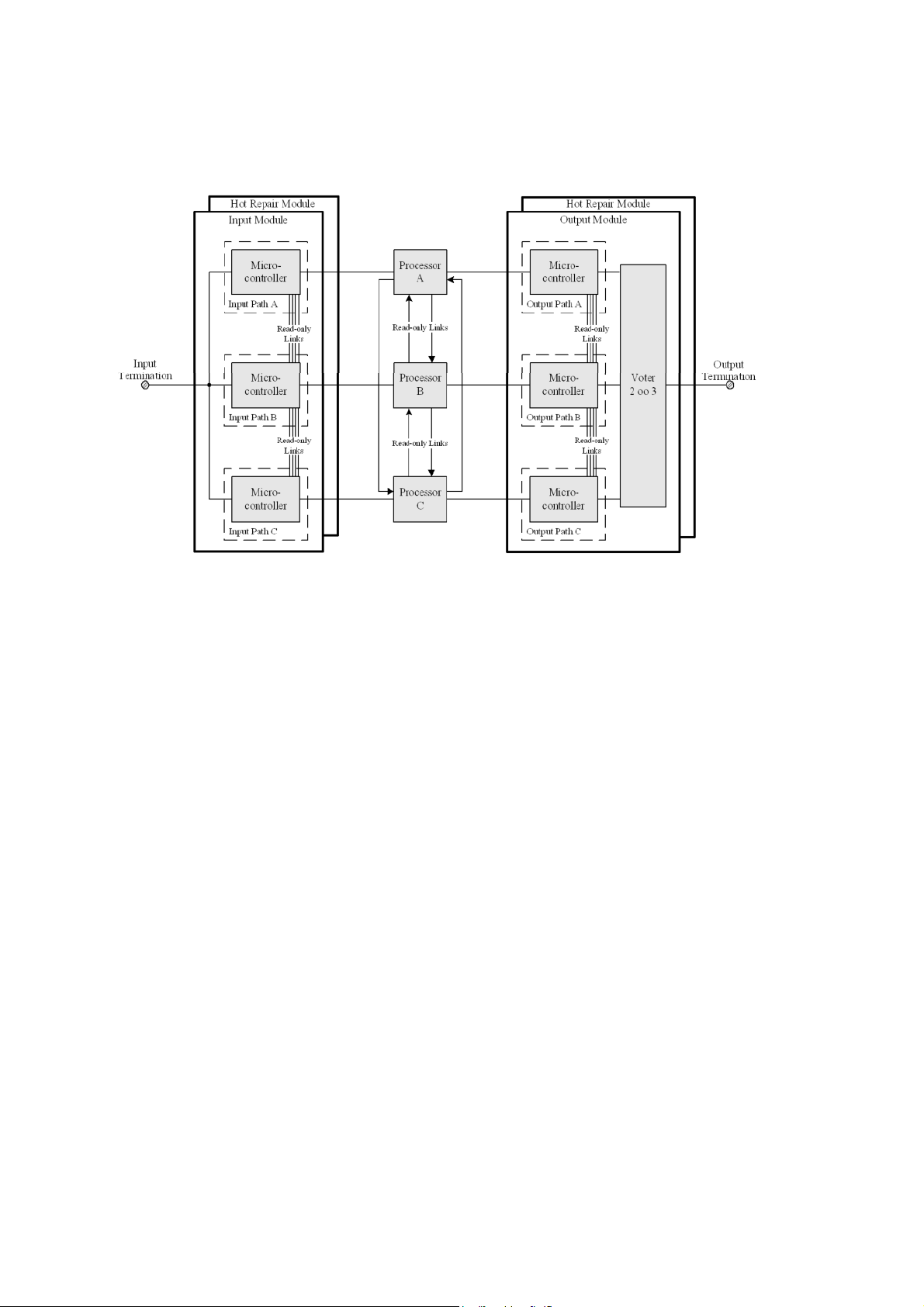
Figure 1-1. SC300E Architecture
As can be
architecture from input modules to output modules. All SC300E input and output modules
interface to three isolated I/O communications buses, each being controlled by one of the three
main
At the input modules, field signals are filtered and then split, via isolating circuitry, into three
identical, signal processing paths. Each path is controlled by a microcontroller that co
ordinates signal path proc
processor, via one of the I/O communications buses.
Each of the main processors communicates with its neighbours via read only, serial
communications links. The main processors synchronise at least once per application logic
execution cycle, and each reads the input, output and diagnostic status of its neighbours.
Each processor correlates and corrects its memory image of the current state of the system
using a 2-oo-3 software vote, logging any discrepancies found in a local diagnostic history
table.
Each processor then executes its programmed application logic and sets its respective
outputs, via the I/O communications bus, to the required state.
seen from the block diagram in Figure 1-1 a SC300E system has a fully triplicated
processor modules.
essing, testing and signal status reporting to its respective main
-
Commanded output states are received by an output module’s microcontrollers which, using 2
oo-3 hardware voters, set the outputs to the field. Any discrepancy between a commanded
output
state and the field output is detected by the microcontrollers and reported to the
appropriate main processor.
-
Page 3
Chassi
s
Model
s
October
2005–
Issue 4
3
Triguard
SC300E Chassis Models
All input and output modules can be configured to use a hot spare partner module. In the event
of failure of the main I/O module its duty is taken over (manually or automatically) by the hot
spare
partner, allowing repairs to be effected
.
HARDWARE
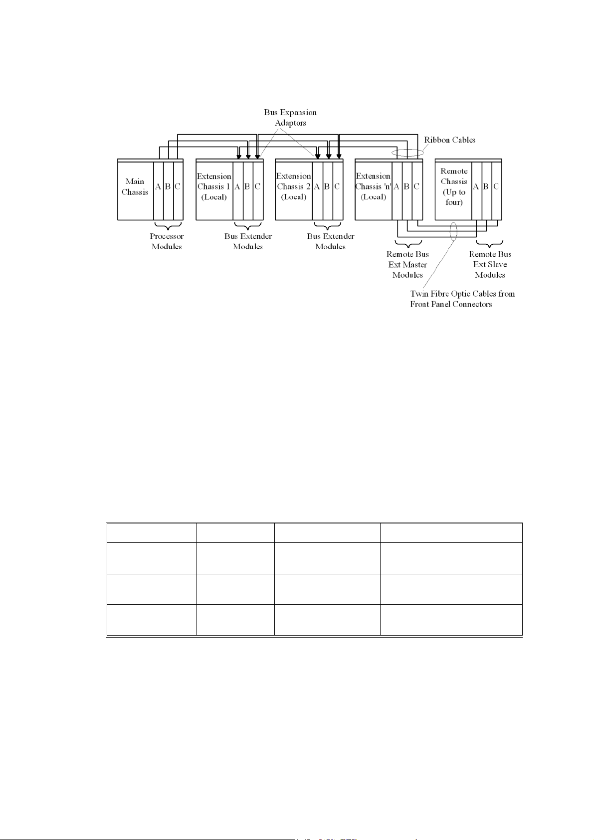
The system
can
be
comprises a main chassis and up to 14 extension chassis (of which 11 can be re
chassis,
using a multi-drop technique. Each chassis can accommodate up to 10 I/O modules so that a
fully
populated SC300E system can contain 150 I/O modules.
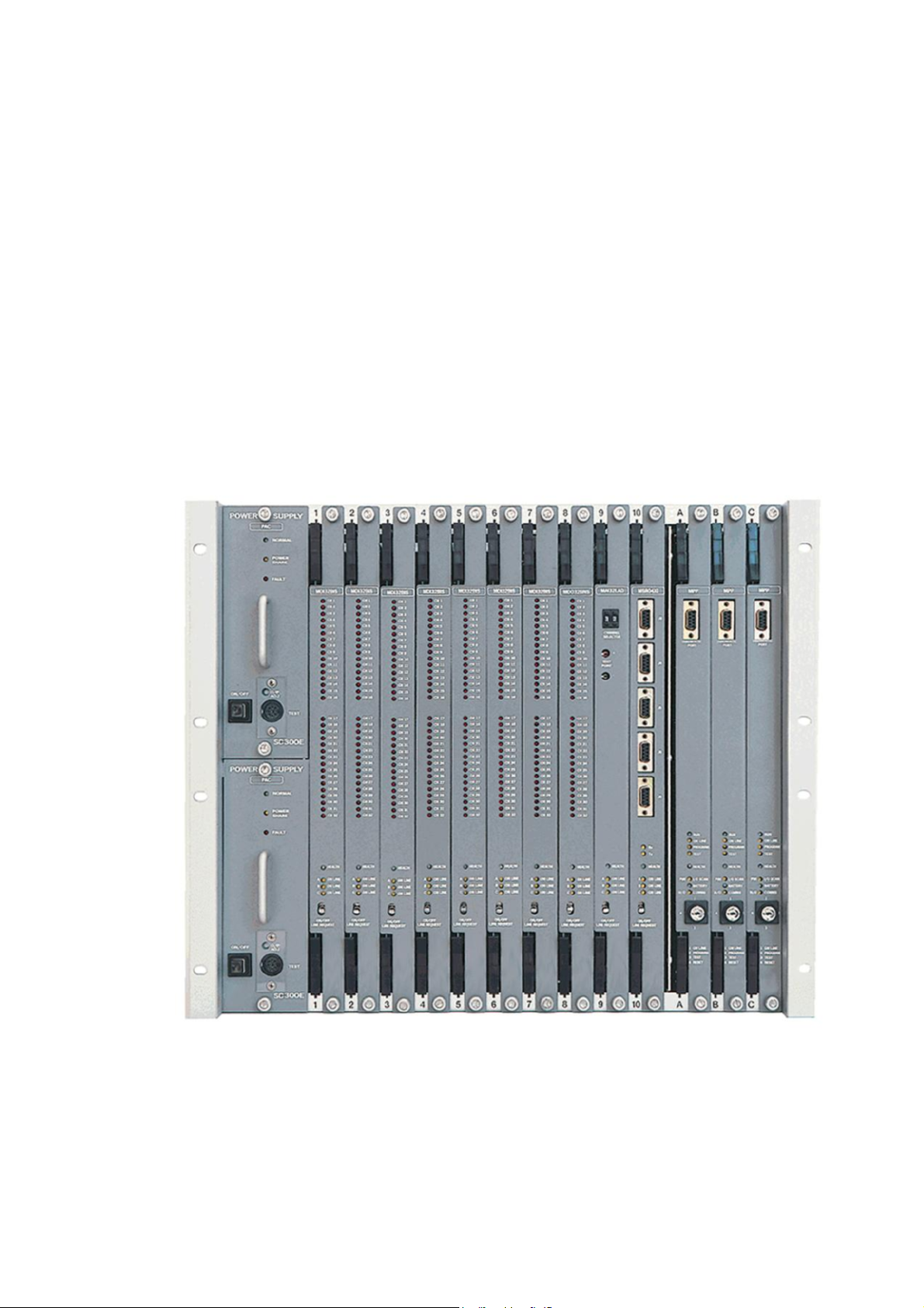
Blanking plates
Unpopulated slots can be covered with blanking plates if required.
circuits are accommodated mainly within a number of identical box chassis which
individually configured and interconnected to form the required system layout. A system
mote
connected via fibre optic cables) interconnected via a set of standard ribbon cables
Figure 1-2. Fully loaded chassis
Page 4
4
Chassi
s
Model
s
October
2005–
Issue 4
T
riguard
SC300E
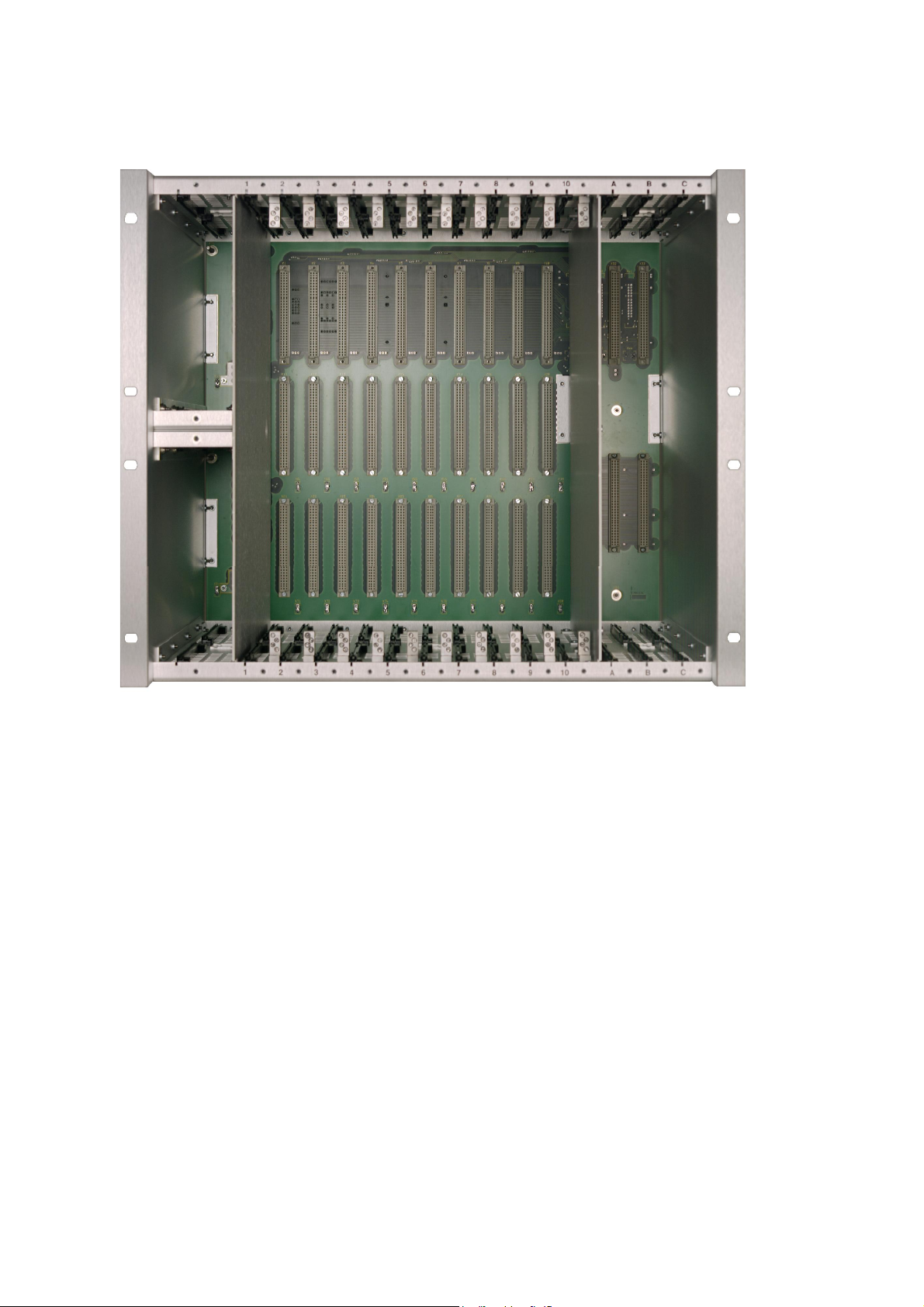
Figure 1-3. Chassis front view
Page 5

Chassi
s
Model
s
October
2005–
Issue 4
5
Triguard
SC300E Chassis Models
Figure 1-4. Chassis rear view
Page 6
6
Chassi
s
Model
s
October
2005–
Issue 4
T
riguard
SC300E
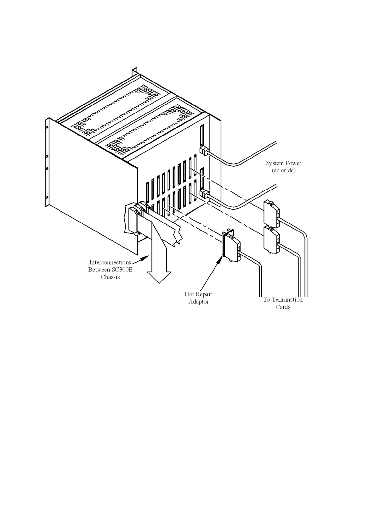
Figure 1-5. Chassis rear view showing cabling arrangement
Page 7
Chassi
s
Model
s
October
2005–
Issue 4
7
Triguard
F
igure 1-6. Chassis interconnections for system layout with remote chassis
SC300E Chassis Models
CHASSIS TECHNICAL DATA
The chassis variants covered by this document differ only in the basic equipment (excluding I/O
modules) fitted into them and whether they can be powered from 110/230Vac or 24Vdc. Table
1-1 lists the details of each variant.
Type No
CXP10A11
CXP10D24
CXB10A11
Type
Main
Main
Extension
Table 1-1. Chassis variants
110/230Vac
24Vdc
110/230Vac
Power
Equipment fitted
3 Processors
2 Power Supplies
3 Processors
2 Power Supplies
3 Bus Extenders
2 Power Supplies
Page 8

8
Chassi
s
Model
s
October
2005–
Issue 4
T
riguard
SC300E
Table 1-1. Chassis variants
Type No
CXB10D24
CXM10A11
CXM10D24
CXS10A11
CXS10D24
Type
Extension
Extension Master 110/230Vac
Extension Master 24Vdc
Extension Slave
Extension Slave
Power
24Vdc
110/230Vac
24Vdc
ASSOCIATED DOCUMENTATION
Reference
3 Bus Extenders
2 Power Supplies
3 Remote Bus Extender Masters
2 Power Supplies
3 Remote Bus Extender Masters
2 Power Supplies
3 Remote Bus Extender Slaves
2 Power Supplies
3 Remote Bus Extender Slaves
2 Power Supplies
Title
Equipment fitted
008-5100
008-5098
008-5105
008-5106
008-5115
008-5117
008-5118
008-5217
MPP Processor Module User Manual
PDC24/PAC Chassis Power Supplies User Manual
MBB Bus Extender Module User Manual
THR Hot Repair Adaptor User Manual
TBA Bus Expansion Ad
MRB04XM Remote Bus Extender Master Module User Manual
MRB01XS Remote Bus Extender Slave Module
TBT Bus Terminator User Manual
aptor User Manual
Page 9

Chassi
s
Model
s
October
2005–
Issue 4
9
SPECIFICATION
24Vdc
(
CXS10D24
):
16.2
kg
Model
Triguard
See under “Weight as supplied”
SC300E Chassis Models
Construction
Finish
Cooling
Overall size (mm)
Overall size (inches)
Weight empty
Weight as supplied (no I/O modules)
2mm aluminium alloy to BS5251(NS4)H4
Anodised
Convection cooled via ventilation holes in top and
bottom
483W x 400H x 486D
19W x 15.8H x 19.2D
8.6 kg
M
ain chassis:
110/230Vac (
24Vdc (
Extension chassis:
110/230Vac (
24Vdc (
Master remote chassis:
110/230Vac (
24Vdc (
Slave remote chassis:
110/230Vac (
surfaces
CXP10A11):
CXP10D24):
CXB10A11):
CXB10D24):
CXM10A11):
CXM10D24):
CXS10A11):
17.2 kg
15.1 kg
16.2 kg
17.2 kg
15.1 kg
16.2 kg
16.2 kg
Page 10

10
Chassi
s
Model
s
October
2005–
Issue 4
T
riguard
SC300E
ENVIRONMENTAL SPECIF
The maximum ambient temperature measured at the hottest point within the Triguard system
shall
not be greater than 60 degrees centigrade.
Temperature operating:
Temperature
Humidity:
EMC/RFI
Vibration/Shock:
Certification:
General Certification:Ref. Triguard SC300E Product Guide (ref 008-5209).
storage:
Immunity:
ICATION
+5°C to +60°C
-
25°C to +70°C
5% to 95% non-condensing at ambient < 40°C
Tested and certified to IEC 1131-Part 2 1994
Tested and certified to IEC 1131-Part 2 1994
TRANSPORT AND HANDLING
The chassis must be transported and stored in its original packing material which should be
retained
for this purpose.
Page 11

Chassi
s
Model
s
October
2005–
Issue 4
11
Triguard
SC300E Chassis Models
TECHNICAL DESCRIPTIO
N
PHYSICAL
The chassis box has two s
bolted
to
top and bottom plates and to a multilayer printed board backplane that carries all
module
facilitate c
partitions
processors.
insertion/e
insertion. The PSU slots have guide pins at the lower right and, if the chassis is an ac variant,
ac power supply studs at the upper left to prevent the insertion of dc power u
connections and interconnections. The top and bottom plates are perforated to
ooling. The plates also carry guides for the I/O modules and support vertical
separating and screening the I/O modules from the power supplies and the
The front edges of the top and bottom plates are flanged to engage the
jection levers on the modules and the flanges have guide marks to assist module
ide plates with flanges to enable 19 inch rack mounting, they are
nits.
Mechanical coding blocks
All Input/Output modules carry two mechanical coding blocks equipped with pins which mate
with
holes in corresponding blocks in the chassis and prevent the module being inserted into
the wrong slot. The pins in the module coding blocks are factory installed in a pattern
determined by the module and corresponding set screws are removed from the chassis coding
blocks
to
enable fitting. Unused holes are plugged with set screws.
The chassis mechanical coding block configurations are given in Table 2-1.
Figure 2-1 shows an unpopulated chassis but the presence of ac power supply studs signifies
that
it is an ac
for other variants they would contain the modules detailed in Table 1-1.
variant. In a main chassis the three right hand slots would contain processors,
Page 12

12
Chassi
s
Model
s
October
2005–
Issue 4
T
riguard
SC300E
Nomenclature
MDI32BIS (3-2-0)
MDI16BNS
MDI
32FIS
MDO32BNS
MDO16FNS
MAD32LAD/MAD
MAO04NND
MHB44IND
MSR04XI
MDI32BIS (3-2-1)
Table 2-1. Chassis/Module mechanical coding configurations
Module mechanical coding positions
Upper coding block
1 2 3 4 1 2 3 4
x x x x
x x x x
x x x x
x x x x
x x x x
x x x
x x x
x x x x
X
x x x x
x x x
Lower coding block
The coding positions shown can be used for both module and chassis settings.
For MODULE setting X = INSERT PIN
For CHASSIS setting X = REMOVE SCREW
Page 13

Chassi
s
Model
s
October
2005–
Issue 4
13
Triguard
SC300E Chassis Models
AC PSU stud
Slot for PSU 1
Slot for PSU 2
Power supply slots
1 and 2
I/O module slots
1
to
10
Upper coding
blocks
Pro ces sor slo ts
A, B,C
PSU guide pin
Module guides
Figure 2-1. Front view of unpopulated chassis
Lower coding
blocks
Page 14

14
Chassi
s
Model
s
October
2005–
Issue 4
T
riguard
SC300E
BACKPLANE
Figure 2-2. Rear view of chassis showing backplane detail
The backplane is a multilayer printed circuit bo
and
carries all the interconnections and input/output connectors.
The backplane provides:
• A dual power and ground plane distribution system
• Processor to processor and processor to I/O module communicat
• ‘Rear plug up’ field I/O connectors
ard that forms the rear plate of the box chassis
ion buses
Page 15

Chassi
s
Model
s
October
2005–
Issue 4
15
Triguard
SC300E Chassis Models
• A ‘rear plug up’ expansion connector for each bus
• A rear mounted diagnostic port for each processor
• Polarised power input connectors
•
• Spade terminal earth connectors for optional chassis earthing
• Spade terminal earths for optional Field I/O cable earthing
Many of the above functions are allocated specific areas with alphabetic references on the
backplane as shown in Table 2-2.
PSU status output connectors
Table 2-2. Backplane areas and their function
Area
a
b
c I/O Field Connectors
d
Function
System bus
I/O Field Connectors
System bus
e
f
g
h
i
k Power input connectors
Expansion bus connectors
Watchdog timer connectors (not active)
Diagnostic connectors
Power supply units
PSU status connectors
Rear plug up technique
In the ‘rear plug up’ technique, connectors fitted to the front of the backplane have wire wrap
tails
protruding from the back of the board and are fitted with shrouds to form rear connectors.
The technique is used on the three expansion buses in area ‘e’ and on all the Field I/O
connectors in areas ‘b’ and ‘c’. The connectors are all DIN41612 types.
CONNECTOR DETAILS
The following pages contain details and pinouts of the backplane connectors viewed from the
rear.
Area ‘a’ -
System bus
Area ‘a’ contains the system bus connections to connector J1 on each I/O module.
Page 16

16
Chassi
s
Model
s
October
2005–
Issue 4
T
riguard
SC300E
‘X’ signifies a pin fitted
Figure 2-3. Field I/O connectors ‘b’ and ‘c’ layout
Page 17

Chassi
s
Model
s
October
2005–
Issue 4
17
Triguard
SC300E Chassis Models
Areas ‘b’ and ‘c’ -
The connectors in areas ‘b’ and ‘c’ are the field connectors for the I/O modules and, apart from
pin
1c
which is always chassis earth, the pin functions depend upon the module in use in each
slot.
Refer to the User Manual for the module for details of the pin functions. Figure 2-3 shows
the
layout of the connectors; ‘x’ signifies
fitted.
None of the pins in the middle column are fitted. The ‘rear plug up’ shrouds (Figure 2-4)
fitted to all Field I/O connectors support connector retention. When I/O modules are fitted as a
Hot
Repair pair, special Hot Repair Adaptors are fitted to the appropriate Field connectors (Ref.
Section
1.6, Associated documentation).
Field I/O
a pin available for use, ‘o’ signifies that the pin is not
Figure 2-4. Field connector shroud and coders
Area ‘d’ -
The three connectors in area ‘d’ connect th
system
setting by linking them together. Figure 2-5 shows the connector layout and Figure 2-6 shows
the identification link chassis address coding for all the chassis in a system.
NOTE -
System bus
e processor modules and interface modules to the
bus. Pins 7 to 10 in columns b and c of the connectors are used for chassis address
Default setting is with no links fitted.
Page 18

18
Chassi
s
Model
s
October
2005–
Issue 4
T
riguard
SC300E
UNIT
ID
‘X’ signifies a pin fitted
Figure 2-5. Connectors ‘d’ layout showing chassis address link location
Page 19

Chassi
s
Model
s
October
2005–
Issue 4
19
Triguard
SC300E Chassis Models
Figure 2-6. Chassis address link coding
Page 20

20
Chassi
s
Model
s
October
2005–
Issue 4
T
riguard
SC300E
Area ‘e’ -
Connectors in area ‘e’ provide the means to extend the system bus to extension chassis. If
more than one extension chassis is to be linked in, an Expansion Bus Adaptor must be fitted
to these connectors (Ref. Section 1.6, Associated documentation).
Processor expansion bus
‘X’
signifies a pin fitted
Figure 2-7. Connector ‘e’ layout
Page 21

Chassi
s
Model
s
October
2005–
Issue 4
21
Triguard
SC300E Chassis Models
Area ‘g’ -
The connectors (26 pin IDC) in area ‘g’ are diagnostic ports, one for each processor; their
signals are the same as those available at the diagnostic ports on the processor fron
(refer to the MPP User Manual 008-5100).
Processor diagnostic ports
Areas ‘h’ -
Do not remove the clear plastic covers from the backplane areas ‘h’, the power supply
terminations
Each area ‘h’ contains the connections at the rear of the related PSU, they are not normally
available and are protected by a clear plastic cover which should not be removed.
When ac power is used an AC Stud is fitted through the backplane at the top right of each area
‘h’ (viewed from the rear) to prevent DC Power Units being fitted.
Areas ‘j’ -
Power supply unit connectors
WARNING
they are protecting may carry lethal voltages.
Power supply status
t panels
Each area ‘j’ contains the alarm connector (Figure 2-8) for the adjacent Power Supply Unit
which enables remote, volt free alarm indications. The connectors are 4 pin Phoenix Combicon.
Pins
1 and 2 are connected across a pair of relay contacts which are normally open. During
normal
operation the relay is energised and the contacts are closed but will open under fault
conditions such as:
Over tempe ratur
Over or under voltage
Relay failure
Loss of input power
Pin 3 is linked to pin 1 and pin 4 is linked to pin 2 to duplicate the output.
The PSHARE LINK above the lower alarm connector carries a signal between the two power
units
to
enable power sharing so that both units carry an equal share of the load.
e
Page 22

22
Chassi
s
Model
s
October
2005–
Issue 4
T
riguard
SC300E
Figure 2-8. PSU Alarm connectors
Areas ‘k’ -
Each Area ‘k’ contains the Power Input connector (Figure 2-9) for the related PSU, the same
input
connector, a 9-way MATE-N-LOK, can be used for either ac or dc power supplies
depending upon which type of PSU is fitted.
Power input
Figure 2-9. Power input connectors
EARTHING
The chassis metalwork is extensively and efficiently earthed to the Power Input earth via the
backplane track and the earthing
terminals
areas ‘b’ and ‘c’.
are available adjacent to the Power Input connectors and all the Field connectors in
pads on the front of the backplane. Additional earthed spade
Page 23

Chassi
s
Model
s
October
2005–
Issue 4
23
Triguard
SC300E Chassis Models
SERVICING
SCOPE
No servicing is necessary.
Do not remove the clear plastic covers from the backplane areas ‘h’, the power supply
terminations
Chassis repair is by unit replacement. A faulty chassis is not repairable in the field, it should be
replaced by a new unit and returned for repair.
SERVICE SUPPORT
WARNING
they are protecting may carry lethal voltages
SPARE PARTS
Spare parts and technical advice can be obtained from your local area office.
 Loading...