

Page 1

TrustedTM
PD-CF800
TM
Trusted
Cabinets
Introduction
The CF800 range of cabinets is available in either the standard or High EMI attenuation formats. The
difference between the CF800 (Standard) and CF800E (High Attenuation) cabinets is in the level of
EMI gasketing provided. The CF800 cabinet is finished in a 100% painted configuration while the
CF800E version has passivated metal edges to doors and side panels, and is fitted with special EMI
gaskets to provide metal to metal contact which increases EMI attenuation
Both types of cabinet are supplied as a basic frame to which infill panels and accessories can be
added.
EMI attenuation tests have been performed by a third party and results are available upon request.
When ordering external parts for a High Attenuation cabinet, the integrator must use the letter ‘E’ at the
end of the prefix, e.g. the prefix for a rear cover for the High Attenuation cabinet is RCE.
This Product Description contains the detailed assembly instructions for the cabinets.
Features
• Fast and efficient self-assembly flat pack design.
• Dimensions 2104H x 800W x 800D. Other sizes and designs available to
order.
• Standard finishes are RAL 7032 and RAL 7035. Other finishes available to
order.
• Rigid construction, modular design, high capacity.
• Optional side covers allow for single or multiple bay arrangements.
• Normal and high attenuation (EMC) versions available as standard.
• Increased protection cabinets certified up to IP65 are also available.
• Front access, or front and rear access available as standard options.
Issue 6 Sep 05 PD-CF800 1
Page 2

Trusted
Issue Record
Issue
Number Date Revised by Technical CheckAuthorised by Modification
TM
Cabinets CF800
6 Sep J W Clark
Format
Issue 6 Sep 05 PD-CF800 2
Page 3
Trusted
TM
Cabinets CF800
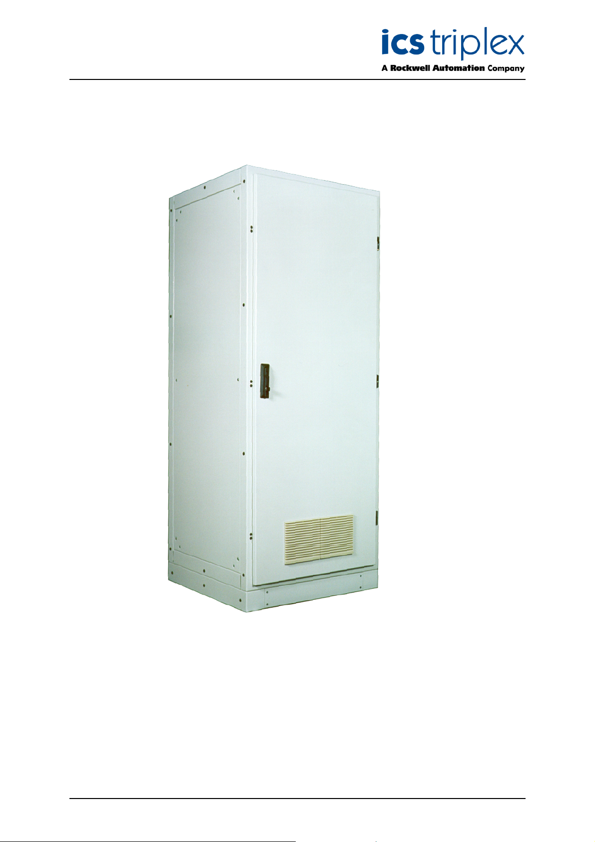
Figure 1 CF800 Layout
Issue 6 Sep 05 PD-CF800 3
Page 4

Trusted
TM
Cabinets CF800
Table of Contents
1. Description......................................................................................................................................7
1.1. Basic Cabinet Frame Kit – CF800(E) .............................................................................................7
1.2. Rear Cover RC(E) ..........................................................................................................................9
1.3. Side Covers SC(E) .......................................................................................................................10
1.4. Cabinet Doors DP(E), DV(E), DM(E), DGR(E) AND DGL(E).......................................................11
2. Installation ....................................................................................................................................13
Figures
Figure 1 CF800 Layout .............................................................................................................................3
Figure 2 Basic Cabinet Frame Assembly .................................................................................................7
Figure 3 Rear Cover .................................................................................................................................9
Figure 4 Side Covers ..............................................................................................................................10
Figure 5 Cabinet Door ............................................................................................................................11
Figure 6 Plinth Fixing Details ..................................................................................................................13
Figure 7 Anti-vibration Mounting.............................................................................................................14
Issue 6 Sep 05 PD-CF800 4
Page 5

Trusted
TM
Cabinets CF800
Notice
The content of this document is confidential to ICS Triplex Technology Ltd. companies and their
partners. It may not be given away, lent, resold, hired out or made available to a third party for any
purpose without the written consent of ICS Triplex Technology Ltd.
his document contains proprietary information that is protected by copyright. All rights are reserved.
T
Microsoft, Windows, Windows 95, Windows NT, Windows 2000, and Windows XP are registered
trademarks of Microsoft Corporation.
The information contained in this document is subject to change without notice. The reader should, in
all cases, consult ICS Triplex Technology Ltd. to determine whether any such changes have been
made. From time to time, amendments to this document will be made as necessary and will be
distributed by ICS Triplex Technology Ltd.
Information in this documentation set may be subject to change without notice and does not represent
a commitment on the part of ICS Triplex Technology Ltd.
The contents of this document, which may also include the loan of software tools, are subject to the
confidentiality and other clause(s) within the Integrator Agreement and Software License Agreement.
No part of this documentation may be reproduced or transmitted in any form or by any means,
electronic or mechanical, including photocopying and recording, for any purpose, without the express
written permission of ICS Triplex Technology Ltd.
Disclaimer
The illustrations, figures, charts, and layout examples in this manual are intended solely to illustrate the
text of this manual.
The user of, and those responsible for applying this equipment, must satisfy themselves as to the
acceptability of each application and use of this equipment.
This document is based on information available at the time of its publication. While efforts have been
made to be accurate, the information contained herein does not purport to cover all details or variations
in hardware or software, nor to provide for every possible contingency in connection with installation,
operation, or maintenance. Features may be described herein which are present in all hardware or
software systems. ICS Triplex Technology Ltd. assumes no obligation of notice to holders of this
document with respect to changes subsequently made.
ICS Triplex Technology Ltd. makes no representation or warranty, expressed, implied, or statutory with
respect to, and assumes no responsibility for the accuracy, completeness, sufficiency, or usefulness of
the information contained herein. No warranties of merchantability or fitness for purpose shall apply.
Issue 6 Sep 05 PD-CF800 5
Page 6

Trusted
TM
Cabinets CF800
Revision and Updating Policy
All new and revised information pertinent to this document shall be issued by ICS Triplex Technology
Ltd. and shall be incorporated into this document in accordance with the enclosed instructions. The
change is to be recorded on the Amendment Record of this document.
Precautionary Information
WARNING
Warning notices call attention to the use of materials, processes, methods, procedures or limits which
must be followed precisely to avoid personal injury or death.
CAUTION
Caution notices call attention to methods and procedures which must be followed to avoid damage to
the equipment.
Notes:
Notes highlight procedures and contain information to assist the user in the understanding of the
information contained in this document
Warning
RADIO FREQUENCY INTERFERENCE
Most electronic equipment is influenced by Radio Frequency Interference (RFI). Caution should be
exercised with regard to the use of portable communications equipment around such equipment.
Signs should be posted in the vicinity of the equipment cautioning against the use of portable
communications equipment.
MAINTENANCE
Maintenance must be performed only by qualified personnel, otherwise personal injury or death, or
damage to the system may be caused.
Caution
HANDLING
Under no circumstances should the module housing be removed.
Associated Documents
Product Descriptions (PD) provide product specific information.
The Safety Manual contains the recommended safety requirements for the safety system design.
The PD8082B – Toolset Suite provides specific guidance on system configuration and application
generation.
The Operator and Maintenance Manual contains general guidelines on maintenance and diagnostic
procedures.
For technical support email: support@icstriplex.com
Issue 6 Sep 05 PD-CF800 6
Page 7

Trusted
TM
Cabinets CF800
1. Description
WARNING
A FULLY ASSEMBLED SINGLE BAY CABINET WILL WEIGH APPROXIMATELY 172kg (378lbs).
INTEGRATORS MUST OBSERVE ALL NECESSARY PRECAUTIONS WHEN HANDLING HEAVY WEIGHTS.
1.1. Basic Cabinet Frame Kit – CF800(E)
Figure 2 below shows an exploded view of the basic cabinet frame.
Figure 2 Basic Cabinet Frame Assembly
Issue 6 Sep 05 PD-CF800 7
Page 8

Trusted
No special tools are required to assemble the TrustedTM CF800 range of cabinets.
The basic cabinet frame is assembled as follows.
TM
Cabinets CF800
1. Assemble the plinth (Items 7 and 8) using 8-off M6 x 16 CSK screws.
2. Fit the lower cross members (Item 2) and upper cross members (Item 3) to the front main
rame (Item 1), using M6 x 20 hexagonal bolts.
f
3. Fit the rear main frame (Item 1) to the lower and upper cross members, using M6 x 20
hexagonal bolts. Tighten all bolts.
4. Fit the 8-off gusset plates to each corner to link the cross members to the front and rear
frames. Use M5 x 10 pan head Taptite screws. Tighten all Taptites.
5. Fit the roof plate gasket to the top of the cabinet, then fit the roof plate using M6 x 16 pan
head screws. Tighten the pan head screws.
6. Fit the assembled plinth to the bottom of the cabinet using 3-off M10 bolts. Use the fourth
hole for the main cabinet M10 earth stud. Tighten securely. The earth stud may be fitted in
any one of the four locations dependent upon the layout of equipment within the cabinet.
7. With the main cabinet frame standing upright, fit the Floor (Item 6) using M6 x 20 hexagonal
bolts. Tighten all bolts.
8. Link all piece parts with earth braids to the M5 earth studs provided.
Note: Front main frames are supplied already fitted with eye-bolts, doors and swingframe (when
specified). Rear main frames are supplied already fitted with eye-bolts, door or rear panel, and
rear equipment sheet (when specified).
Issue 6 Sep 05 PD-CF800 8
Page 9

Trusted
TM
Cabinets CF800
1.2. Rear Cover RC(E)
Figure 3 shows the assembled cabinet main frame together with the rear cover.
Figure 3 Rear Cover
The rear cover is fitted to the cabinet main frame as follows.
1. Position the angle on the inside of the rear cover (Item 2) on the lower door return on the rear
main frame.
2. Push the rear cover in to the vertical position and secure to the rear frame using the four ¼-
turn catches.
3. Link all piece parts with earth braids to the M5 earth studs provided.
Issue 6 Sep 05 PD-CF800 9
Page 10

Trusted
TM
Cabinets CF800
1.3. Side Covers SC(E)
Figure 4 shows the assembled cabinet main frame, fitted rear cover and side covers.
Figure 4 Side Covers
The side covers are fitted to the cabinet main frame as follows.
1. Position the side cover (Item 1) in the recess on the side of the cabinet main frame. Secure
in position using the 10-off M6 x 16 pan head screws provided. Tighten the screws.
2. Repeat 1. above for the other side cover.
Issue 6 Sep 05 PD-CF800 10
Page 11

Trusted
TM
Cabinets CF800
1.4. Cabinet Doors DP(E), DV(E), DM(E), DGR(E) AND DGL(E)
Figure 5 Shows the assembled cabinet main frame with a plain door.
Figure 5 Cabinet Door
Issue 6 Sep 05 PD-CF800 11
Page 12

Trusted
TM
Cabinets CF800
Five types of cabinet door are available as detailed below.
Item Part No. Description
1 DP(E) Door Plain Universal
2 DV(E) Door Vented Universal
3 DM(E) Door Matrix Universal
DGR(E) Door Glazed Right-Hand Hinge
4
5 DGL(E) Door Glazed Left-Hand Hinge
Doors are supplied fully assembled and hinged to the front or rear main frames as specified. The
doors are hinged on the right-hand side as standard. To modify a universal door (the hinges on glazed
doors cannot be changed over) so that it is hinged on the left-hand side, proceed as follows:
1. Remove the door from the main frame by removing the hinge pins.
2. Remove the hinges and catches from the main frame and change their positions over.
3. Turn the door through 180 degrees and fit it to the main frame. Replace the hinge pins
removed in 1. above.
4. Door handles are fitted for right-hand hinge as standard. To change the handle for left-hand
hinge, remove the hexagonal head centre screw and the two pan head self tapping screws
securing the handle to the door. Turn the handle and latch mechanism through 180
0
and refit
the screws.
5. Close and check the door for alignment. Adjust if necessary.
6. Fully tighten all hinge and catch fixings to complete the assembly.
Notes: Door locks have key number 1333 as standard.
Issue 6 Sep 05 PD-CF800 12
Page 13

Trusted
TM
Cabinets CF800
2. Installation
WARNING
ENSURE THAT THE CABINET IS ADEQUATELY SUPPORTED DURING PERIODS THAT IT IS
SUSPENDED BY LIFTING GEAR. OPENING A CABINET DOOR WITHOUT ADEQUATE SUPPORT
WHILST IT IS SUSPENDED CAUSES MOVEMENT OF THE CENTRE OF GRAVITY. THIS
ONSTITUTES A HAZARD TO PERSONNEL AND MAY CAUSE SERIOUS INJURY OR DEATH.
C
WHEN LIFTING A SINGLE-BAY CABINET, ENSURE THAT THE LOAD IS EQUALLY
DISTRIBUTED BY USING A 4-WAY LIFTING SLING.
WHEN LIFTING A MULTI-BAY CABINET, IT IS RECOMMENDED THAT A MULTI-BAY LIFTING
KIT (MBL, MBLF4 OR MBLF5) IS USED.
The plinth on which the cabinet is mounted may be welded or bolted in position as required. Fixing
details for the plinth are shown in Figure 6 below.
Figure 6 Plinth Fixing Details
Issue 6 Sep 05 PD-CF800 13
Page 14

Trusted
The instructions detailed below are applicable to whichever method of securing the cabinet in position
is used.
Install the cabinet as follows:
The cabinet may be used in applications where the fitting of anti-vibration strips is necessary. Antivibration Kits AV are supplied and fitted between the plinth and the floor as shown in Figure 7 below.
TM
Cabinets CF800
1. Position the cabinet in the required location using an overhead crane, forklift or rollers as
ppropriate.
a
2. Open the cabinet door and remove the split floor plate (Item 6 shown in Figure 2) to gain
access to the lower surface of the plinth.
3. Bolt the cabinet in position through the 8-off holes in the lower surface of the plinth using M12
bolts of a suitable length. Alternatively, weld the lower surface of the plinth to the floor if a
metal surface.
4. Refit the split floor plate removed in 2. then close the cabinet door.
Figure 7 Anti-vibration Mounting
Issue 6 Sep 05 PD-CF800 14
Page 15

Trusted
TM
Cabinets CF800
This page is intentionally blank
Issue 6 Sep 05 PD-CF800 15
Page 16

 Loading...