

Page 1
Installation Instructions 3
10000040330
Bedienungsanleitung 17
Operating instructions 35
Operating instructions 51
Operating instructions 67
en
de
fr
es
it
Active Converter, Universal
931U-C9A2C-OP
DIR 10000040330
(Version 00)
Page 2

2
Page 3
en
931U-C9A2C-OP
Contents
Operation 4
Installation 5
Setup 8
Calibration 13
3
Page 4
en
−
+
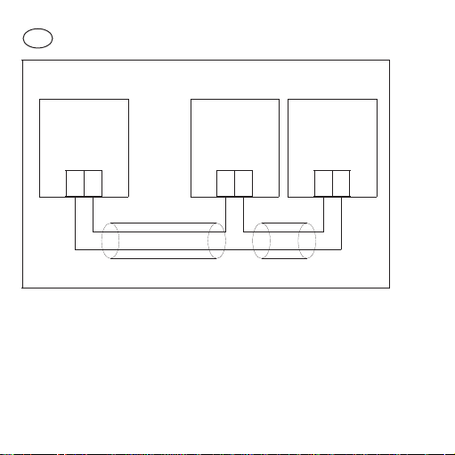
Twisted pair cable
–+ +
−
Connection diagram for loop powered transmitter outputs.
Loop
Powered
Transmitter
Receiving
device
(Current
inputs)
Power
Supply
931U-C9A2C-OP
• Operation
General
The 931U-C9A2C-OP is a DIN rail device that converts signals
from commonly used industrial signal sources and provides a fully
isolated 4-20 mA signal that varies in proportion to the input signal.
4
Page 5

Loop powered operation
WARNING
Loop powered transmitters use the drop in voltage across the
outputs to generate power for the electronics. The 931U-C9A2COP requires a 10-40 V drop to operate correctly. Using a power
supply that provides this voltage drop will comply with the
instrument’s UL/CSA listing.
Receiving devices are placed in series with the 931U-C9A2C-OP
and introduce additional load resistances into the loop. The total
loop load for a 4-20 mA loop powered by supply voltage Vs is
R
= 50 x (Vs-10).So, for example, a 931U-C9A2C-OP powered
loop
from a 24 V DC supply can drive a 700 Ω loop load.
• Installation
• Disconnect power prior to installation
• Installation only by Qualified personnel
• Follow all applicable local and national electrical codes
• Do not cover the case holes.
• Case front should be closed in normal operation.
• Take care to avoid touching the internal components when the
front panel is open.
5
Page 6
Location
Locate the instrument in an area that is free from dust, moisture
and corrosive gases.
Cleaning
The case can be wiped with a damp cloth. De-energize the unit
before cleaning.
Connections
Strip wires to 7 mm from the ends. Use a suitable ferrule for
multistranded wires (do not solder).
Use 12-28 AWG Cu Wire rated for temperatures above 70 °C Only,
tighten to 4.5 lb-In.
For effective protection from electromagnetic noise, all signal cables
must be shielded, or located on conductive trays or in conduits.
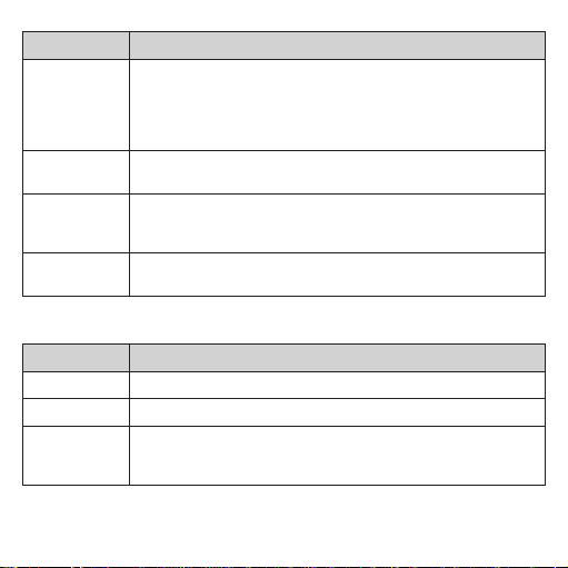
Connections
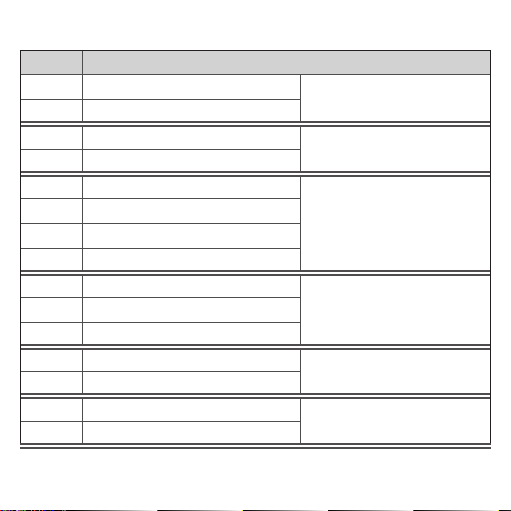
Term inal Signal
5 Loop –
6 Loop +
1 Signal +
2 Signal –
6
Output (4-20 mA )
Thermocouple
Page 7
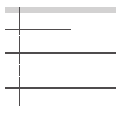
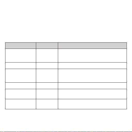
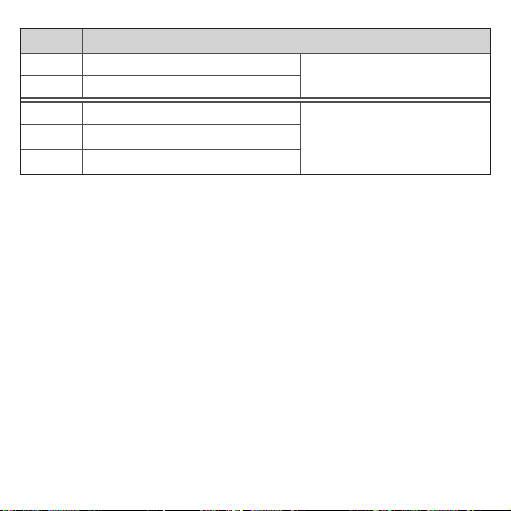
Term inal Signal
1 Asense
3 A
2 B
4 Bsense
1 Asense
3 A
2 B
3 A
2 B
1 Signal +
2 Signal –
1 Signal +
2 Signal –
3 A
1 Wiper
2 B
4-wire RTD
(or Resistance)
3-wire RTD
(or Resistance)
2-wire RT D
(or Resistance)
Voltaqe
(mV or V)
Current
(mA)
Potentiometer
7
Page 8
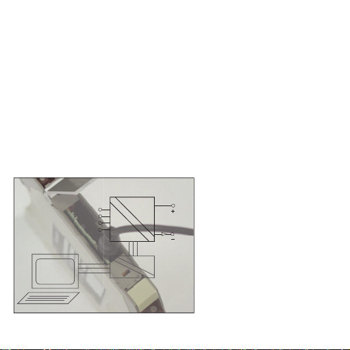
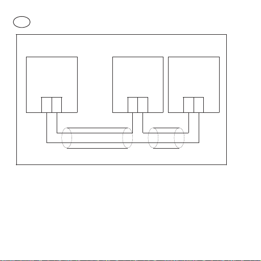
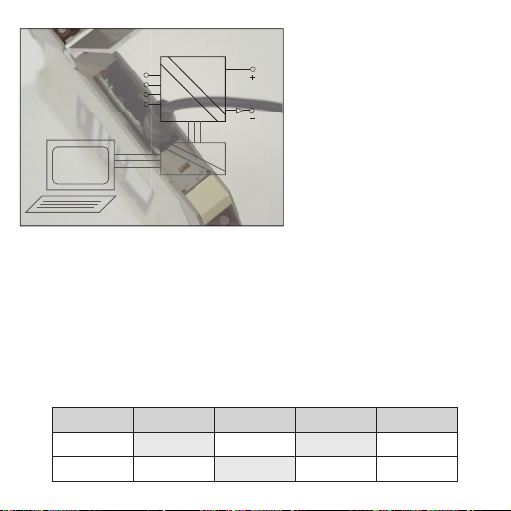
• Setup
1
2
3
4
Input
Output
PC
5
6
931U-C9A2C-OP
931U-Cable
Getting started
1. Connect the 931U-C9A2C-OP to a spare USB Port on your PC
using the 931U-Cable interface kit (See diagram above).
2. Switch on the 931U-Cable.
3. Start the Setup/Calibration software on your PC. [The latest
setup/calibration software is available for free download from
our website.]
4. Apply power to the 931U-C9A2C-OP.
Block diagram showing
931U-Cable and PC
connection for Setup
8
Page 9
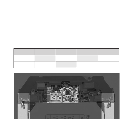
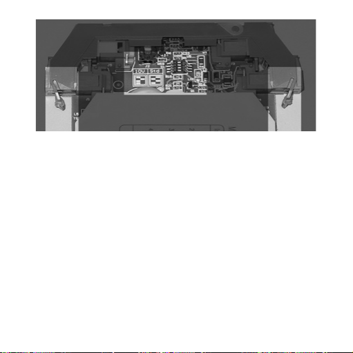
Attenuator switch
For input voltages above 1 V.
1. Push in the lugs marked A & B below.
2. Pull the electronics forward gently to reveal the attenuator
switches.
3. Set the switches to the position required.
4. Recalibrate the inputs (see over).
Bit 1 2 3 4
1 V On Off On Off
10 V Off On Off Off
A
Attenuator switch location and front panel locating lugs A & B.
B
9
Page 10

Changing the instrument setup
1. Open the Setup/Calibration software.
2. Enter your initials using the ‘Enter Initials’ command from the
‘Device’ menu (shortcut is F7).
3. Press the ‘Get from instrument’ button at the bottom of the
screen (shortcut is F9).
4. The screen will now show the instruments current configuration.
5. Save the current configuration to disk using the ‘Save as’
command from the ‘File’ menu.
6. Setup the instrument to suit your application via the
input screen (press F5) and output screen (press F6).
7. Return to the main screen, check the details are correct and
press the ‘Send to Instrument’ button (shor tcut F8).
Note: You are required to enter a password to change the
instruments setup. The default password is 100. Make a note of
the instrument password if you change it - otherwise you will have
to send the instrument back to us.
8. Save the changes to disk as a record of changes you have
made.
10
Page 11
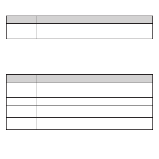
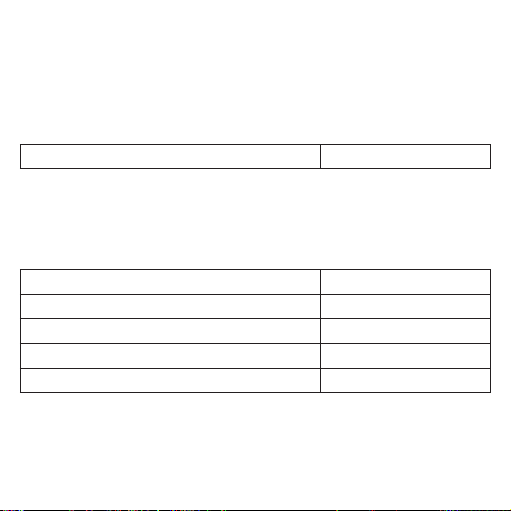
Main screen
Fields Description
ID Tag User defined field (e.g., PT1015-2)
User reference User defined field (e.g., Pump 1015 bearing)
Input screen
Set the input type by pressing the appropriate button - relevant
fields (as shown below) will appear.
Fields Description
Engineering unit Sets the units used for the input low and high set tings.
Input Low The input value corresponding to ‘zero’ (4 mA) output.
Input High The input value corresponding to ‘full scale’ (20 mA) output.
Damping factor Sets th e damping fa ctor for the inbuilt digit al filter. Accept s values from
# of samples The number o f samples averag ed for each measurement. T he effec t of this
1-99 .
setting depends on the input type. Normally set around 50.
11
Page 12
Fields Description
10V Attenuator This c heck box all ows you to set ‘Input High’ and ‘Input Low’ valu es in the
Burnout Sets the actio n in case of sens or burn-out or disconnec tion. Ups cale sends
Type Allows y ou to choos e between ther mocouple or RTD types. Not shown for
Input connection Is the input connected in two, three or four wire mode. For R TD and resist-
software in volts up to 10 V.
Note: The 931U-C9A2C-OP will only accept values up to 10 V if the attenuator s witch on the main board is s et to the 10 V setting. If yo u change the
switches you must recalibrate the voltage input.
the output to 22 mA, downscale sends the output to 3.7 mA.
other input types. Note: you c an set up your own linea risation tabl es here by
choosing ‘user defined’.
ance inputs only. Sets up the lead length compensation.
Output screen
Fields Description
Range Sets the output range, normally 4.00 mA to 20.00 mA .
Transfer function X1 gives the usual proportional output.
Output action
12
Set to direct or reversed. Direct gives the usual proportional output. For
reversed action, the input low value gives a 20 mA output and the high value
a 4 mA output.
Page 13

• Calibration
General
All instruments are fully calibrated before leaving the factory and
should not need adjustment until the next scheduled calibration.
However, if you change the voltage attenuator switches, you must
recalibrate the voltage input.
Equipment requirements
• Suitable accurate signal source for the inputs
(see calibration points table below)
• An accurate digital multimeter (accurate to 0.05 mV and
±0.1 μA)
• A suitable regulated power supply, AB 1606-XLP30E
• 931U-Cable connected to a PC with the Setup/Calibration
software.
Digital multimeters are frequently better at measuring voltages than
currents, so you may wish measure the voltage across an accurate
standard resistor (say 10 Ω ±0.05 %) when monitoring the output
current.
13
Page 14
Connections
Connect the output circuit as shown on page one with the
multimeter in place of the receiving device.
Connect the 931U-C9A2C-OP up to a PC running the setup/
Calibration software (as if you were going to change the setup).
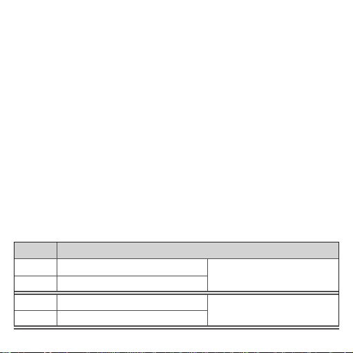
Input Calibration points
Range Values Notes
Volts/Thermocouple 10 mV, 20 mV,
mA 20 mA
RTD/Resistance
Individual calibration As selected Allows you to recalibrate any of the points above
Fine adjust Current input Fine tune the adjustment for t he range yo u have
All All ranges Complete c alibration of a ll points. Internal switches
14
50 mV, 80 mV,
200 mV, 1 V
100 Ω, 200 Ω,
500 Ω, 800 Ω,
2 kΩ, 10 kΩ
If the inte rnal switches a re set to 10 V, y ou must
supply a signal ten times the displayed value, e.g. 10
V for the 1V point.
Use four wire mode
selected.
must be in the 1V position.
Page 15

Input calibration
1. Save the current calibration to disk (select ‘Save Calibration
data’ from the ‘Device’ menu).
2. Select ‘Calibrate Input’ from the ‘Device’ menu.
3. Enter the calibration password (Default is 101).
4. Choose the calibration required (see Input calibration points
table for guidance).
5. Supply the signals requested by the software and follow the
instructions on screen. Press the ‘Done’ button when finished.
Output Calibration
1. Measure the output current.
2. Select ‘Calibrate output’ from the ‘Device’ menu.
3. Enter the calibration password.
4. The 4 mA adjustment window will open. Adjust the output to
4.00 mA using the buttons shown.
Note: you can use PgUp and PgDn controls on the keyboard for
fine adjustment and <CNTRL> + PgUp and <CNTRL> + PgDn
for coarse adjustment.
5. Press Next when the output has settled at 4.00 mA.
6. Repeat the procedure for the 20.00 mA adjustment.
15
Page 16
7. Press OK to save the changes to the instrument.
This completes the output calibration.
• Accessories
Marker
1492-M5X10
Power Supply
24 VDC Output
15 W 1606-XLP15E
30 W
50 W 1606-XLP50E
100 W 1606-XLP100E
120 W (5 A)
DIR 10000040330
(Version 00)
16
1606-XLP30E
1606-XLE120E
Page 17

de
931U-C9A2C-OP
Inhaltsverzeichnis
Betrieb 18
Installation 19
Konfiguration 22
Kalibrierung 28
17
Page 18
de
−
+
Twisted Pair-Kabel
–+ +
−
Anschlussdiagramm für Signalgeberausgänge in Zweileitertechnik
Signalgeber
in Zweileiter-
technik
Empfangs-
gerät (Strom-
eingang)
Strom-
versorgung
931U-C9A2C-OP
• Betrieb
Allgemein
931U-C9A2C-OP ist ein DIN-Tragschienengerät (TS35), das
Signale von im industriellen Umfeld gängigen Signalquellen
umsetzt und ein sich proportional zum Eingangssignal änderndes
vollständig isoliertes 4-20 mA Signal bereitstellt.
18
Page 19

Schleifengespeister Betrieb
Schleifengespeiste Trennwandler nutzen den Spannungsabfall
zwischen den Ausgängen, um Strom für die Elektronik zu
erzeugen. Für einen ordnungsgemäßen Betrieb des 931U-C9A2COP ist ein Spannungs abfall von 10-40 V erforderlich. Der Einsatz
einer Spannungsquelle zur Bereitstellung dieses Spannungsabfalls
ist gemäß der Registrierung des Instruments in der UL/CSA-Liste
zulässig.
Empfangsgeräte werden mit dem 931U-C9A2C-OP in Reihe
geschaltet und erhöhen den Lastwiderstand in der Schleife. Die
Gesamtschleifenlast, bei einer durch die Versorgungsspannung Vs
gespeisten 4-20 mA Schleife, beträgt R
Ein 931U-C9A2C-OP, das von einer 24 V DC Spannungsquelle
versorgt wird, kann beispielsweise eine Schleifenlast von 700 Ω
betreiben.
Schleife
= 50 x (Vs-10 ).
• Installation
Allgemein
Die Installation dieser Geräte darf nur von speziell ausgebildetem
Fachpersonal unter Beachtung der in dieser Dokumentation
enthaltenen Informationen sowie der in dem jeweiligen Land
geltenden Bestimmungen für die elektrische Verdrahtung und
Sicherheitsvorschriften durchgeführt werden.
19
Page 20

Die Lüftungsöffnungen im Gehäuse dürfen nicht abgedeckt
werden.
Im normalen Betrieb sollte die Gehäusefront geschlossen sein.
Standort
Montieren Sie das Instrument in einer staubfreien, trockenen
Umgebung, in der keine korrodierenden Gase auftreten.
Reinigung
Das Gehäuse kann mit einem feuchten Tuch gereinigt werden.
Trennen Sie die Geräte von der Netzspannung, bevor Sie sie
reinigen.
Anschlüsse
Isolieren Sie die Anschlussleitung an beiden Enden auf 7 mm
ab. Versehen Sie mehradrige Leiter mit einer geeigneten Adernendhülse (nicht löten).
Verwenden Sie eine für Temperaturen von über 70 °C zugelassene
Anschlussleitung (12-28 AWG), und schließen Sie diese mit einem
Drehmoment von 0,5 Nm (4,5 lb-In) an.
Als effektiven Schutz vor elektromagnetischer Störeinstrahlung
müssen alle Signalleitungen eine Schirmung aufweisen oder in
leitfähigen Kabelkanälen bzw. in Rohren geführt werden.
20
Page 21
Anschlüsse
Klemme Signal
5 Schleife –
6 Schleife +
1 Signal +
2 Signal –
1 Leitungswiderstand A
3 A
2 B
4 Leitungswiderstand B
1 Leitungswiderstand A
3 A
2 B
3 A
2 B
1 Signal +
2 Signal –
Ausgang (4-20 mA)
Thermoelement
4-Draht-RTD
(bzw. -Widerstand)
3-Draht-RTD
(bzw. -Widerstand)
2-Draht-RTD
(bzw. -Widerstand)
Spannung
(mV oder V)
21
Page 22
Klemme Signal
1 Signal +
2 Signal –
3 A
1 Schleifer
2 B
Strom
(mA)
Potentiometer
• Konguration
Erste Schritte
1. Schließen Sie den 931U-C9A2C-OP mit Hilfe des Schnittstellenkits
931U -
Cable an eine freie USB-Schnittstelle Ihres PCs (siehe
Abbildung oben) an.
2. Schalten Sie das 931U-Cable ein.
3. Starten Sie die Konfigurations-/Kalibrierungssoftware auf Ihrem PC.
[Der jeweils aktuellste Stand der Konfigurations-/Kalibrierungssoftware steht auf unserer Website zum kostenlosen Download zur
Verfügung.]
4. Schließen Sie das 931U-C9A2C-OP an die Stromversorgung an.
Warnung: Achten Sie bei geöffneter Frontplatte darauf, die Komponenten im
Inneren des Geräts nicht zu berühren.
22
Page 23
1
2
3
4
Eingang
Ausgang
PC
5
6
931U-C9A2C-OP
931U Kabel
Das Blockdiagramm zeigt
einen 931U-Cable- und PCAnschluss für das Setup
Dämpfungsschalter
Bei Eingangsspannungen von über 1 V.
1. Drücken Sie die mit A & B markierten Verriegelungshebel (siehe
unten) nach innen.
2. Ziehen Sie die Elektronik behutsam nach vorne, bis die Dämpfungs-
schalter sichtbar werden.
3. Bringen Sie die Schalter in die jeweils erforderliche Schalterstellung.
4. Rekalibrieren Sie die Eingänge (siehe weiter unten).
Bit 1 2 3 4
1 V On Off On Off
10 V Off On Off Off
23
Page 24
A
Position des Dämpfungsschalters und Lasche A & B zur Positionierung der Frontplatte.
Konguration des Instruments ändern
1. Öffnen Sie die Konfigurations-/Kalibrierungssoftware.
2. Geben Sie über den Befehl ‘Enter Initials’ (Initialen eingeben) im
Menü ‘Device’ (Gerät) (Kurztaste F7) Ihre Initialen ein.
3. Drücken Sie die Taste ‘Get from instrument’ (Von Instrument
abrufen) unten in der Anzeige (Kurztaste F9).
4. In der Anzeige ist nun die aktuelle Konfiguration des Instruments
zu sehen.
5. Speichern Sie die aktuelle Konfiguration auf den Datenträger.
Verwenden Sie dazu den Befehl ‘Save as’ (Speichern unter) im
Menü ‘File’ (Datei).
24
B
Page 25

6. Konfigurieren Sie das Instrument über die Eingangsanzeige
(drücken Sie F5) und Ausgangsanzeige (drücken Sie F6)
entsprechend den Anforderungen Ihrer Anwendung.
7. Kehren Sie zur Hauptanzeige zurück, überprüfen Sie, ob
die Angaben stimmen, und drücken Sie die Taste ‘Send to
Instrument’ (An Instrument senden) (Kurztaste F8).
Hinweis: Zum Ändern der Konfiguration des Instruments ist die
Eingabe eines Passworts erforderlich. Das Standardpasswort ist
100. Merken bzw. notieren Sie sich das Passwort des Instruments,
bevor Sie es ändern. Andernfalls ist es erforderlich, das Instrument
an uns einzusenden.
8. Speichern Sie die Änderungen auf den Datenträger, um eine
Aufzeichnung der vorgenommenen Änderungen zur Hand zu
haben.
25
Page 26
Hauptanzeige
Felder Beschreibung
ID Tag Benutzerdefiniertes Feld (Beispiel: PT1015-2)
User reference Benutzerdefiniertes Feld (Beispiel: Lager der Pumpe 1015)
Eingangsanzeige
Legen Sie den Typ des Eingangssignals durch Drücken der betreffenden Taste fest. Die unten aufgeführten Felder werden angezeigt.
Felder Beschreibung
Engineering Unit Legt die Einheiten fest, die für di e Einstellungen für ‘Input low’ (Eingang
Input Low Der einem Ausgang von ‘Null’ (4 m A) entsprechende Eingangswert.
Input High Der einer ‘Full Scale’ (Vollaussteuerung) (20 mA) am Ausgang entspre-
Damping Factor Legt den Dä mpfungsfaktor für den integrier ten digitalen F ilter fest.
# of sa mples Die Anzahl der zur Dur chschnit tsermit tlung herangezo genen Stichproben
26
niedrig) bzw. ‘Input high’ (Eingang hoch) verwendet werden.
chende Eingangswert.
Akzeptiert Werte von 1 bis 99.
pro Messung. Die Auswirkung dieser Einstellung hängt vom Eingangstyp ab.
Wird in der Regel auf einen Wert von etwa 50 gesetzt.
Page 27

Felder Beschreibung
10V At tenuator Über dieses Kä stchen können Sie für ‘Input High’ (Eingang ho ch) und ‘Input
Burnout Legt fest , welche Ak tion im Fall eines Durchbr ennens bzw. Abklemmen s
Type Hie r können Sie zwischen den Typ en ‘Thermocouple’ ( Thermoe lement) oder
Input connection Ansc hluss des Eingangs im 2-, 3- oder 4 -Leitermodus. Nur bei R TD- und
Low’ (Ein gang niedrig) in der Soft ware Wert e bis zu 10 V festle gen. Hinweis:
931U-C 9A2C-OP akzeptiert Werte bis zu 10 V nur, wenn der Dämpfungsschal ter auf der Haup tleiterpl atte auf d ie 10 V-Eins tellung ges etzt ist . Wenn
Sie die Schalterstellungen ändern, müssen Sie den Spannungseingang
rekalibrieren.
des Sensors durchgeführ t wird. Bei ‘Upscale’ (Hoch) geht der Ausgang auf
22 mA, bei ‘Downscale’ ( Tief) geht der Ausgang auf 3,7 mA.
‘RT D’ wählen. W ird bei and eren Eingangst ypen nicht angezeigt. Hinweis:
Durch Auswahl von ‘U ser defined’ (B enutzerd efiniert ) können Sie hier I hre
eigenen Linearisationstabellen einrichten.
Widerstandseingängen. Legt die Leitungslängenkompensation fest.
27
Page 28

Ausgangsanzeige
Felder Beschreibung
Range Legt den Ausgangsbereich fest. Beträgt in der Regel 4,00 mA bis 20,00 mA.
Transfer function Mit X1 erhalten Sie den normalen proportionalen Ausgang.
Output action
Wählen Sie hierfür ‘Direct’ (Direkt) oder ‘Reversed’ ( Invertiert). ‘Direct’ (Direkt) liefert den normalen proportionalen Ausgang. Bei der Ak tion ‘Reversed’
(Inver tiert) liefer t der minimale Eingangswert ausgangsseitig 20 mA und das
maximale Eingangssignal entsprechend 4 mA am Ausgang.
• Kalibrierung
Allgemein
Alle Geräte sind zum Zeitpunkt der Auslieferung vollständig
kalibriert. Eine Anpassung ist in der Regel erst im Rahmen der
nächsten planmäßigen Kalibrierung erforderlich. Wenn Sie
allerdings die Spannungsdämpfungsschalter ändern, müssen
Sie eine Rekalibrierung des Spannungseingangs durchführen.
Anforderungen an die Betriebsmittel
• Geeignete und genaue Signalquelle für die Eingänge
(siehe Kalibrierungspunkttabelle unten)
• Ein präzises digitales Multimeter (mit einer Genauigkeit von
0,05 mV und ±0,1 μA)
28
Page 29

• Eine geeignete regulierte Spannungsquelle (AB 1606-XLP30E)
• 931U-Cable angeschlossen an einen PC mit der
Konfigurations-/Kalibrierungssoftware.
Digitale Multimeter eignen sich häufig besser zur
Spannungsmessung als zur Messung von Strom. Messen Sie
daher bei der Überwachung des Ausgangsstroms die Spannung
über einen genauen Standardwiderstand (z. B. 10 Ω ±0,05 %).
Anschlüsse
Schließen Sie den Ausgangsschaltkreis wie auf Seite 1 dargestellt
an das Multimeter an.
Schließen Sie das 931U-C9A2C-OP an einen PC an, auf dem die
Konfigurations-/ Kalibrierungssoftware vorhanden ist (wie bei einer
Änderung der Konfiguration).
29
Page 30

Eingangskalibrierungspunkte
Bereich Werte Hinweise
Volts/Thermocouple 10 mV, 20 mV,
mA 20 mA
RTD/Resistance
Individual calibration As Selected Ermöglicht die Reka librierung jedes beliebigen der
Fine adjust Current Input Zur Feineinstellung der von Ihnen ausgewählten
All All Ranges Vollständige Kalibrierung aller Punkte. Die internen
50 mV, 80 mV,
200 mV, 1 V
100 Ω, 200 Ω,
500 Ω, 800 Ω,
2 kΩ, 10 kΩ
Sind die int ernen Schalter auf 10 V gese tzt, müs sen
Sie ein Sign al bereitstell en, das dem Z ehnfachen
des angezeigten Wer ts entspricht ( Beispiel: 10 V für
den 1 V-Punkt.
Verwenden Sie den 4-Leitermodus.
oben genannten Kalibrierungspunkte.
Bereichsanpassung.
Schalter müssen sich in der 1V-Position befinden.
Eingangskalibrierung
1. Speichern Sie die aktuelle Kalibrierung auf dem Datenträger
(indem Sie im Menü ‘Device’ (Gerät) die Option ‘Save Calibration
data’ (Kalibrierungsdaten speichern) auswählen).
2. Wählen Sie im Menü ‘Device’ (Gerät) die Option ‘Calibrate Input’
(Eingang kalibrieren) aus.
30
Page 31

3. Geben Sie das Kalibrierungspasswort ein
(Standardkalibrierungspasswort lautet 101).
4. Wählen Sie die erforderliche Kalibrierung aus (weitere
Informationen finden Sie in der Tabelle mit den
Eingangskalibrierungspunkten).
5. Stellen Sie die von der Software angeforderten Signale bereit,
und folgen Sie den Anweisungen auf der Anzeige. Wenn Sie den
Vorgang abgeschlossen haben, drücken Sie die Taste ‘Done’
(Fertig).
Ausgangskalibrierung
1. Messen Sie den Ausgangsstrom.
2. Wählen Sie im Menü ‘Device’ (Gerät) die Option ‘Calibrate
output’ (Ausgang kalibrieren) aus.
3. Geben Sie das Kalibrierungspasswort ein.
4. Das Fenster zur 4 mA-Anpassung wird geöffnet. Ändern Sie den
Ausgang mit Hilfe der unten dargestellten Tasten in 4,00 mA.
Hinweis: Mit den Bedienelementen PgUp (Zurückblättern)
bzw. PgDn (Vorblättern) auf der Tastatur können Sie eine
Feineinstellung vornehmen. Die Bedienelemente <CNTRL>
(STRG) + PgUp (Zurückblättern) und <CNTRL> (STRG) + PgDn
(Vorblättern) erlauben eine Grobeinstellung.
31
Page 32

5. Wenn der Ausgang auf 4,00 mA eingestellt ist, drücken Sie
‘Next’ (Weiter).
6. Wiederholen Sie den Vorgang, um die 20,00 mA-Anpassung
vorzunehmen.
7. Drücken Sie OK, um die Änderungen am Gerät zu speichern.
Damit ist die Ausgangskalibrierung abgeschlossen.
32
Page 33

• Zubehör
Marker
Power Supply
24 VDC Output
1492-M5X10
15 W
30 W 1606-XLP30E
50 W 1606-XLP50E
100 W
120 W (5 A) 1606-XLE120E
1606-XLP15E
1606-XLP100E
DIR 10000040330
(Version 00)
33
Page 34

34
Page 35

fr
931U-C9A2C-OP
Table des matières
Fonctionnement 36
Installation 37
Configuration 40
Etalonnage 46
35
Page 36

fr
−
+
Câble à paires torsadées
-+ +
−
Schéma de connexion pour sorties transmetteur alimenté en boucle.
Transmetteur
alimenté
en boucle
Appareil de
réception
(entrées
courant)
Alimentation
électrique
931U-C9A2C-OP
• Fonctionnement
Généralités
L'931U-C9A2C-OP est un élément encliquetable sur rail DIN,
qui convertit les signaux provenant des sources de signaux
36
Page 37

communément utilisées dans l'industrie et délivre un signal 4-20 mA
entièrement isolé, qui varie proportionnellement au signal d'entrée.
Fonctionnement avec alimentation en boucle
Les transmetteurs alimentés en boucle utilisent la chute de
tension aux bornes des sorties pour générer l'alimentation des
composants électroniques. L'931U-C9A2C-OP requiert une chute
de tension de
10-40 V pour fonctionner correctement. Le fait d'utiliser une
alimentation électrique pour produire cette chute de tension est
conforme à la norme UL/CSA en matière d'instrumentation.
Les unités de réception sont placées en série avec l'931U-C9A2C-OP
et introduisent des charges résistives additionnelles dans la boucle.
La charge de boucle totale pour une boucle 4-20 mA alimentée par
une tension d'alimentation Vs est égale à R
Ainsi, par exemple, un 931U-C9A2C-OP alimenté par une tension
de 24 V c.c. est capable de commander une charge de 700 Ω.
= 50 x (Vs-10 ).
loop
• Installation
Généralités
Ces unités doivent exclusivement être installées par un personnel
qualifié conformément aux informations figurant dans le présent
37
Page 38

manuel, et toutes les règles nationales pertinentes en matière de
câblage électrique et de sécurité doivent être respectées.
Ne recouvrez pas les orifices de ventilation du boîtier.
La partie avant du boîtier devrait être fermée en fonctionnement
normal.
Emplacement
Placez l'instrument dans une zone exempte de poussière,
d'humidité et de gaz corrosifs.
Nettoyage
Le boîtier peut être nettoyé à l'aide d'un chiffon humide. Mettez
l'unité hors tension avant de procéder au nettoyage.
Connexions
Dénudez les extrémités de fil sur 7 mm. Utilisez un embout
approprié pour fils multibrins (ne soudez pas).
Utilisez exclusivement du fil de cuivre de section 12-28 AWG conçu
pour des températures supérieures à 70 °C, serrez avec un couple
de 4,5 lb-In.
Pour une protection efficace contre le bruit électromagnétique,
tous les câbles de signal doivent être blindés, ou posés dans des
chemins ou conduits de câbles conducteurs.
38
Page 39

Connexions
Borne Signal
5 Boucle –
6 Boucle +
1 Signal +
2 Signal –
1 Asense
3 A
2 B
4 Bsense
1 Asense
3 A
2 B
3 A
2 B
1 Signal +
2 Signal –
Sortie (4-20 mA)
Thermocouple
RTD (capt eur de tempé rature à résistanc e)
à 4 fils (ou résistance)
RTD (capt eur de tempé rature à résistanc e)
à 3 fils (ou résistance)
RTD (capt eur de tempé rature à résistanc e)
à 2 fils (ou résistance)
Tension
(mV ou V)
39
Page 40

Borne Signal
1 Signal +
2 Signal –
3 A
1 Curseur
2 B
Courant
(mA)
Potentiomètre
• Conguration
Guide de démarrage
1. Branchez l'931U-C9A2C-OP sur un port série RS232 libre de
votre
PC à l'aide du kit interface 931U-Cable (voir le diagramme
ci-dessus).
2. Mettez le 931U-Cable sous tension.
3. Démarrez le logiciel Setup/Calibration (Configuration/
Etalonnage) sur votre PC. [Le dernier logiciel de configuration/
d'étalonnage peut être téléchargé gratuitement depuis notre site
Internet.]
4. Mettre l'931U-C9A2C-OP sous tension.
Avertissement : Prenez soin de ne pas toucher les composants internes
40
lorsque le panneau avant est ouvert.
Page 41

1
2
3
4
Entrée
Sortie
PC
5
6
931U-C9A2C-OP
931U Câble
Schéma-bloc montrant la
connexion 931U-Câble et
PC pour la config.
Commutateur d'atténuateur
Pour les tensions d'entrée supérieures à 1 V.
1. Pressez les languettes repérées par A et B ci-dessous.
2. Faites glisser lentement le circuit imprimé vers l'avant, afin de
faire apparaître les commutateurs d'atténuateur.
3. Réglez les commutateurs à la position requise.
4. Réétalonnez les entrées (voir ci-dessus).
Bit 1 2 3 4
1 V On Off On Off
10 V Off On Off Off
41
Page 42

A
B
Emplacement du commutateur d'atténuateur et des languettes A et B
Changement de la conguration de l'instrument
1. Démarrez le logiciel de configuration/d'étalonnage.
2. Entrez vos initiales en utilisant la commande ‘Enter Initials’
(Entrez les initiales) depuis le menu ‘Device’ (Appareil) (le
raccourci est F7).
3. Appuyez sur le bouton ‘Get from instrument’ (Recevoir de
l'instrument) situé en bas de l'écran (le raccourci est F9).
4. L'écran indique à présent la configuration actuelle des
instruments.
5. Enregistrez la configuration actuelle sur le disque à l'aide de la
commande ‘Save as’ (Enregistrer sous) du menu ‘File’ (Fichier).
42
du panneau avant.
Page 43

6. Configurez l'instrument afin de l'adapter à votre application par
le biais de l'écran ‘input’ (Entrée) (appuyez sur F5), puis par le
biais de l'écran ‘output’ (Sortie) (appuyez sur F6).
7. Retournez à l'écran principal, vérifiez que les détails sont
corrects, puis appuyez sur le bouton ‘Send to Instrument’
(Envoyer à l'instrument) (raccourci F8).
Remarque : Vous devez entrer un mot de passe pour modifier la
configuration des instruments. Le mot de passe par défaut est
100. Notez le mot de passe de l'instrument si vous le modifiez -
sinon, vous allez devoir nous renvoyer l'instrument.
8. Enregistrez les changements effectués sur le disque.
Ecran principal
Champs Description
ID Tag (Etiquette) Champ défini par l'utilisateur (p. ex. PT1015-2)
User reference ( Référence utilisateur) Champ défini par l'utilisateur (p. ex. Pompe 1015
palier)
Ecran d'entrée
Définissez le type d'entrée en actionnant le bouton approprié - les
champs concernés (comme indiqué ci-dessous) apparaissent.
43
Page 44

Champs Description
Engineering unit (Unité de mesure) Permet de définir l'unité utilisée pour les pa ramètres
Input Low La valeur d'entrée correspond à la sortie ‘zéro’ (4 mA).
Input High La valeur d'entrée correspond à la sortie ‘pleine échelle’ (20 mA ).
Damping factor Permet de définir le facteur d'amor tissement pour le filtre numér ique
# of samples Nombr e d'échantillons pris en compte d ans la moyenne de c haque mesur e.
10V Attenuator Cet te case à co cher vous permet de dé finir les valeurs ‘Input High’ ( Entrée
Burnout Définit l'actio n en cas de destr uction (‘ Burnout’) ou de déc onnexion du
Type Vou s permet de chois ir parmi les typ es thermocoupl e ou RTD (capteur
44
d'entrée bas et haut.
intégré. A ccepte les valeurs de 1 à 99.
L'effet de ce pa ramètre dépend du type d'e ntrée. Il e st normalement défin i
à environ 50.
haute) et ‘Input Low’ (Entrée basse) dans le logiciel, en volts jusqu'à 10 V.
Remar que : L'931U-C 9A2C- OP accept e uniquement les v aleurs jus qu'à 10 V
si le commut ateur d'at ténuateur se tr ouvant sur la ca rte-mère est r églé sur
10 V. Si vous modifiez les c ommutateurs, vous d evez réétalonner l'en trée
tension.
capteur. ‘U pscale’ (Augmenta tion) définit la sor tie à 22 mA , ‘Downscale’
(Réduction) définit la sortie à 3,7 mA.
de température à résistance). Non affiché pour les autres types d'entrée.
Remarque : Vous pouvez configurer ici vos propres tables de linéarisation
en sélectionnant ‘user defined’ (défini par l'utilisateur).
Page 45

Champs Description
Input connection Il s'agit de l'entr ée connectée en mode d eux, trois ou qu atre fils. R éservé
aux en trées RT D et résist ance. Défi nit la compensa tion de longueur de
câble.
Ecran de sortie
Champs Description
Range Définit la plage (‘range’) de sortie, normalement 4,00 mA à 20,0 0 mA.
Transfer function (Fonction de transfert) X1 délivre la sortie propor tionnelle usuelle.
Output action
(Action sortie) Définie sur ‘direct’ (directe) ou ‘reversed’ (inver sée). ‘Direct’
délivre la sortie propor tionnelle usuelle. Pour l'action inversée, la valeur
basse d'entrée donne une sor tie de 20 mA et une valeur haute une sortie
de 4 mA.
45
Page 46

• Etalonnage
Généralités
Tous les instruments sont entièrement étalonnés avant de
quitter l'usine et ne devraient pas nécessiter de réglage avant le
prochain étalonnage programmé. Cependant, si vous modifiez les
commutateurs d'atténuateur de tension, vous devez réétalonner
l'entrée tension.
Exigences concernant l'équipement
• Source de signal de précision appropriée pour les entrées
(voir la table des points d'étalonnage ci-dessous)
• Un multimètre numérique précis (précision de 0,05 mV et
±0,1 μA)
• Une alimentation électrique régulée appropriée AB
1606-XLP30E
• 931U-Cable connecté à un PC doté du logiciel de conguration/
d'étalonnage.
Les multimètres numériques sont généralement meilleurs pour
la mesure de tensions que pour la mesure de courant ; par
conséquent, vous pouvez mesurer la tension au moyen d'une
résistance de précision standard (c.-à-d. 10 Ω ±0,05 %) lors du
contrôle du courant de sortie.
46
Page 47

Si vous disposez d'un étalonneur Portacal 1000, vous n'avez pas
besoin du multimètre ni de l'alimentation électrique régulée.
Connexions
Connectez le circuit de sortie comme indiqué en page une, avec
le multimètre en lieu et place de l'unité de réception.
Branchez l'931U-C9A2C-OP à un PC, sur lequel tourne le logiciel
de configuration/d'étalonnage (comme si vous modifieriez la
configuration).
Points d'étalonnage d'entrée
Range (Plage) Valeurs Commentaires
Volts/Thermocouple 10 mV, 20 mV,
mA 20 mA
RTD/Resistance
Individual calibration As selected Vous permet de ré étalonner tout poin t mentionn é
50 mV, 80 mV,
200 mV, 1 V
100 Ω, 200 Ω,
500 Ω, 800 Ω,
2 kΩ, 10 kΩ
Si les commu tateurs inter nes sont réglés sur 10 V,
vous devez fournir un signal égal à dix fois la valeur
affichée, p. ex. 10 V pour le point 1 V.
Utilisation du mode à quatre fils
ci-dessus
47
Page 48

Range (Plage) Valeurs Commentaires
Fine adjust Current input Réglage fin pour la plage, que vous avez sélec-
All All ranges Etalonnage de l'ensemble des points. Les commuta-
tionnée.
teurs internes doivent être sur la position 1 V.
Etalonnage d'entrée
1. Enregistrez l'étalonnage actuel sur le disque (sélectionnez ‘Save
Calibration data’ (Enregistrer données d'étalonnage) depuis le
menu ‘Device’ (Appareil)).
2. Sélectionnez ‘Calibrate Input’ (Etalonner entrée) depuis le menu
‘Device’ (Appareil).
3.
Entrez le mot de passe d'étalonnage (la valeur par défaut est 101).
4. Sélectionnez l'étalonnage requis (voir la table des points
d'étalonnage d'entrée).
5. Délivrez les signaux requis par le logiciel et suivez les
instructions apparaissant à l'écran. Appuyez sur le bouton
‘Done’ (Terminé) une fois terminé.
48
Page 49

Etalonnage de sortie
1. Mesurez le courant de sortie.
2. Sélectionnez ‘Calibrate output’ (Etalonner sortie) depuis le menu
‘Device’ (Appareil).
3. Entrez le mot de passe d'étalonnage.
4. La fenêtre de réglage 4 mA s'ouvre. Réglez la sortie à 4,00 mA à
l'aide des boutons affichés.
Remarque : Vous pouvez utiliser les commandes PgUp et PgDn
du clavier pour le réglage fin, et <CNTRL> + PgUp et <CNTRL>
+ PgDn pour le réglage approximatif.
5.
Appuyez sur ‘Next’ (Suivant) une fois que la sortie est réglée à
4,00 mA.
6. Répétez la procédure pour le réglage 20,00 mA.
7.
Appuyez sur OK pour enregistrer les changements relatifs à
l'instrument.
Ceci termine l'étalonnage de sortie.
49
Page 50

• Accessoires
Marker
1492-M5X10
Power Supply
24 VDC Output
15 W 1606-XLP15E
30 W
50 W 1606-XLP50E
100 W 1606-XLP100E
120 W (5 A) 1606-XLE120E
DIR 10000040330
(Version 00)
50
1606-XLP30E
Page 51

es
931U-C9A2C-OP
Índice
Funcionamiento 52
Montaje 54
Configuración 56
Calibración 62
51
Page 52

es
−
+
Cable de par trenzado
-+ +
−
Diagrama de conexión para salidas de transmisores
alimentados por bucle.
Transmisor
alimentado
por bucle
Dispositivo
receptor
(entradas
de corriente)
Fuente de
alimentación
931U-C9A2C-OP
• Funcionamiento
Información general
El 931U-C9A2C-OP es un dispositivo diseñado para ser montado
en un carril DIN cuya función es la de convertir la señal de fuentes
52
Page 53

industriales de señal de uso común proporcionando una señal
completamente aislada de 4-20 mA que varía proporcionalmente
con la señal de entrada.
Funcionamiento con alimentación por bucle
Los transmisores de señal alimentados por bucle usan la caída
de potencial entre terminales de salida para generar la energía
necesaria para sus componentes electrónicos. El 931U-C9A2COP necesita una diferencia de potencial de 10-40 V para un
funcionamiento correcto. El uso de una fuente de alimentación
que proporcione esta caída de tensión es compatible con la
certificación UL/CSA del instrumento.
Los dispositivos receptores se conectan en serie con el
931U-C9A2C-OP, introduciendo una resistencia adicional a la
carga del bucle. La carga total del bucle en un bucle de 4-20 mA.
con una tensión de alimentación Vs es R
= 50 x (Vs-10 ).
bucle
Así, y a modo de ejemplo, un 931U-C9A2C-OP con una
alimentación de 24 V DC puede actuar sobre una carga de bucle
de 700 Ω.
53
Page 54

• Montaje
Información general
Estas unidades solo podrán ser montadas por personal
convenientemente cualificado y siguiendo las instrucciones que se
detallan en este manual y respetando la reglamentación nacional
vigente referente al cableado eléctrico y a la seguridad.
No tape las orificios de ventilación de la carcasa.
La tapa frontal de la carcasa debe permanecer cerrada durante el
funcionamiento normal del dispositivo.
Emplazamiento
Emplace el instrumento en un lugar en que no esté expuesto a la
humedad, ni al polvo, ni a gases corrosivos.
Limpieza
Use un paño húmedo para limpiar la carcasa. Desconecte el
dispositivo de la alimentación y asegúrese de que no está bajo
tensión antes de limpiarlo.
Conexiones
Quite 7mm de aislante en los extremos de los cables. Use una
virola adecuada para cables de varios hilos (sin soldar).
Emplee exclusivamente cable de cobre de calibre 12-28 AWG
54
Page 55

(estándar USA) para temperaturas nominales superiores a 70 °C,
con un par de apriete de 0,5 Nm (4,5 libras-pulgada).
Para conseguir una protección efectiva frente a las perturbaciones
electromagnéticas, todos los cables de señal deben estar
apantallados, o bien estar emplazados en bandejas portacables
de material conductor o en conductos apropiados.
Conexiones
Borne Señal
5 Bucle –
6 Bucle +
1 Señal +
2 Señal –
1 Resistencia cable A
3 A
2 B
4 Resistencia cable B
1 Resistencia cable A
3 A
2 B
Salida (4-20 mA)
Termopar
RTD de 4 hilos
(o resistencia)
RTD de 3 hilos
(o resistencia)
55
Page 56

Borne Señal
3 A
2 B
1 Señal +
2 Señal –
1 Señal +
2 Señal –
3 A
1 Cursor
2 B
RTD de 2 hilos
(o resistencia)
Voltaje
(mV o V)
Intensidad de corriente
(mA)
Potenciómetro
• Conguración
Primeros pasos
1. Conecte el 931U-C9A2C-OP a un puerto serie RS232 libre de
su ordenador PC. Use para ello el kit de interfaz 931U-Cable
(consulte el diagrama que figura más arriba).
2. Encienda el 931U-Cable.
3
. Arranque el programa de configuración/calibración en el ordenador
PC. [Puede descargar gratis la última versión actualizada del
56
Page 57

programa de configuración/calibración en nuestra página Web.]
1
2
3
4
Input
Output
PC
5
6
931U-C9A2C-OP
931U-Cable
4. Alimente el 931U-C9A2C-OP.
Atención: asegúrese de no tocar los componentes internos cuando el
panel frontal esté abierto.
Diagrama de bloques
de la conexiçon del
931U-C9A2C-OP con el
931U-Cable y el ordenador
PC para el proceso de
configuración
Conmutador de atenuación
Para tensiones de entrada superiores a 1 V.
1. Empuje las lengüetas marcadas con A y B en la figura de abajo.
2. Tire con suavidad de la placa de componentes hasta que los
conmutadores de atenuación queden accesibles.
3. Coloque los conmutadores en la posición requerida.
57
Page 58

4. Calibre de nuevo las entradas (vea más adelante).
Bit 1 2 3 4
1 V On Off On Off
10 V Off On Off Off
A
Emplazamiento del conmutador de atenuación y panel
frontal indicando la posición de las lengüetas A y B.
58
B
Page 59

Cambio de la conguración del instrumento
1. Arranque el programa de configuración/calibración.
2. Introduzca sus iniciales usando el comando ‘Enter Initials’
(introducir iniciales) en el menú ‘Device’ (dispositivo) (la tecla de
acceso rápido es F7).
3. Pulse el botón ‘Get from instrument’ (leer del instrumento) en la
parte inferior de la pantalla (la tecla de acceso rápido es F9).
4. La pantalla muestra a continuación la configuración actual del
instrumento.
5. Grabe en un disco la configuración actual mediante el comando
‘Save as’ (guardar como) del menú ‘File’ (archivo).
6. Configure el instrumento de acuerdo con la aplicación que le
vaya a dar. Utilice para ello las pantallas de entradas (pulse F5)
y de salidas (pulse F6).
7. Vuelva a la pantalla principal, compruebe que los detalles
son correctos y pulse el botón ‘Send to Instrument’ (enviar al
instrumento) (tecla de acceso rápido F8).
Indicación: deberá proporcionar una clave de acceso para cambiar
la configuración del instrumento. La clave por defecto es 100. Si
la cambia, haga una nota con la clave. De lo contrario tendrá que
enviarnos el instrumento.
8. Grabe los cambios en disco para tener una copia de ellos.
59
Page 60

Pantalla principal
Campos Descripción
ID Tag Campo definido por el usuario (p. ej., PT1015-2)
User reference Campo definido por el usuario (p. ej., bomba 1015 rodamiento)
Pantalla de entradas)
Seleccione el tipo de entrada pulsado el botón adecuado, con lo
que aparecerán los campos implicados (tal y como se muestran a
continuación).
Campos Descripción
Engineering unit Seleccion a las unidades pa ra los parámet ros ‘input low’ (nivel bajo de la
Input Low Valor de entrada correspondiente a salida ‘cero’ (4 mA).
Input High Valor de entrada correspondiente a salida ‘amplitud má xima’ (20 mA).
Damping factor Se lecciona el factor de atenuación para el filtro digital integrado. Acepta
# of samples Númer o de muestr eos que se promedian en cada medida. El efecto de
60
entrada) y ‘input high’ (nivel alto de la entrada).
valores en el rango 1-9 9.
este parámetr o depende del tip o de entrad a. Normalmente est á ajustado a
alrededor de 50.
Page 61

10V Attenuator Esta casilla de activaci ón permite seleccionar en el software los va lores de
Burnout Selecciona la acción para el caso de que el sensor se queme o se desco-
Type Permite elegir ent re los tipo s termopar o RT D. No apare ce cuando s e
Input connection Modo de conexión de la entr ada: a 2, 3 o 4 hilos. Solo para entrad as de RTD
‘Input High (nivel alto de entrada)’ y de ‘I nput Low’ (nivel bajo de entrada)
en voltios hasta 10 V.
Indic ación: el 931U-C9A 2C-OP solo acept ará valor es de hast a 10 V si el
conmutador de atenuación de la placa base está en la posición correspondiente a 10 V. Si cambia los conmutadores deberá calibrar de nuevo la
entrada de tensión.
necte. ‘Upsca le’ (nivel al to) pone la s alida a 22 m A, ‘downscale’ {nivel baj o)
pone la salida a 3,7 mA .
haya selecciona do otro tip o de entrada. Indicación: pued e configur ar sus
propias t ablas de linealización seleccionando ‘user defined’ (definido por
el usuario).
y resistencia. Configura la compensación de la longitud del cable.
Pantalla Output (salida)
Campos Descripción
Range
Transfer function X1 brinda la salida proporcional usual.
Output action
Configura el rango de salida. Los valores normales son de 4,00 mA a 20,00 mA.
Las opciones posibles son ‘direct ’ (directa) o ‘reversed’ (invertida). ‘direct’
brinda la salida proporcional usual. Si la actuación debe ser inver tida, a un
nivel de entrada bajo le corresponde una salida de 20 mA, mientras que a un
nivel alto de entrada le corresponde una salida de 4 mA.
61
Page 62

• Calibración
Información general
Todos los instrumentos han sido calibrados en fábrica y no
deberían necesitar recalibración alguna hasta que se cumpla el
plazo previsto para ello. Sin embargo, si usted decide cambiar los
conmutadores de atenuación de tensión, deberá calibrar de nuevo
la entrada de tensión.
Equipamiento requerido
• Una fuente de señal precisa para las entradas
(consulte la tabla de calibración que figura más abajo)
• Un multímetro digital preciso (precisión de hasta 0,05 mV y
±0,1 μA)
• Una fuente de alimentación regulada y adecuada para esta
aplicación, AB 1606-XLP30E
• 931U-Cable conectado a un ordenador PC que disponga del
software de configuración/calibración.
Con frecuencia, los multímetros digitales son más apropiados para
medir voltajes que intensidades de corriente. Por ello,puede ser
más conveniente medir la caída de potencial entre los extremos de
una resistencia estándar precisa (por ejemplo 10 Ω ±0,05 %) para
monitorizar la intensidad de corriente de salida.
62
Page 63

Conexiones
Conecte el circuito de salida tal y como se muestra en la primera
página, sustituyendo el dispositivo receptor por el multímetro.
Conencte el 931U-C9A2C-OP a un ordenador PC en el que
esté funcionando el programa de configuración/calibración (de la
misma forma en que se hace para cambiar la configuración).
Puntos de calibración de la entrada
Range Valores Observaciones
Volts/Thermocouple 10 mV, 20 mV,
mA 20 mA
RTD/Resistance
Individual calibration As selected Le permite volver a calibrar cua lquiera de l os puntos
Fine adjust Current input Ajuste fino para el rango que haya seleccionado
All All ranges Calib ración complet a de todos l os puntos. Los
50 mV, 80 mV,
200 mV, 1 V
100 Ω, 200 Ω,
500 Ω, 800 Ω,
2 kΩ, 10 kΩ
Si los conmutadores internos están en la posición
correspo ndiente a 10V debe rá proporcionar una
señal diez veces superior al valor visualizado en
pantalla, p. ej., 10 V para el punto de calibración 1V.
Emplee el modo de cuatro hilos
mostrados más arriba
conmutadores internos deben estar colocados en la
posición correspondiente a 1V.
63
Page 64

Calibración de la entrada
1. Grabe en disco la calibración actual (seleccione ‘Save
Calibration data’ (guardar datos de calibración) en el menú
‘Device’ (dispositivo)).
2. Seleccione ‘Calibrate Input’ (calibrar la entrada) en el menú
‘Device’ (dispositivo).
3. Introduzca la clave de acceso para la calibración (la clave por
defecto es 101).
4. Seleccione la calibración requerida (como referencia, consulte la
tabla de puntos de calibración).
5. Alimente con las señales que le pida el programa y siga las
instrucciones que aparezcan en pantalla. Pulse el botón ‘Done’
(terminado) cuando haya terminado.
64
Page 65

Calibración de la salida
1. Mida la intensidad de corriente de salida.
2. Seleccione ‘Calibrate output’ (calibrar la salida) en el menú
‘Device’ (dispositivo).
3. Introduzca la clave de acceso para la calibración.
4. Aparece la ventana de ajuste para 4 mA. Ajuste la salida a
4.00 mA usando los botones que se muestran.
Indicación: puede usar las teclas ‘PgUp’ (página arriba) y ‘PgDn’
(página arriba) del teclado para realizar el ajuste fino. Para hacer
un primer ajuste menos exacto puede usar las combinaciones
de teclas <CNTRL> + PgUp y <CNTRL> + PgDn del teclado.
5. Pulse ‘Next’ (siguiente) cuando la salida se haya estabilizado
a 4,00 mA.
6. Repita el procedimiento para el ajuste correspondiente a
20,00 mA .
7. Pulse ‘OK’ para grabar los cambios en el instrumento.
Con ello se completa la calibración de la salida.
65
Page 66

• Accessories
Marker
1492-M5X10
Power Supply
24 VDC Output
15 W
30 W
50 W
100 W
120 W (5 A) 1606-XLE120E
DIR 10000040330
(Version 00)
66
1606-XLP15E
1606-XLP30E
1606-XLP50E
1606-XLP100E
Page 67

it
931U-C9A2C-OP
Indice
Funzionamento 68
Installazione 69
Setup 72
Calibrazione 77
67
Page 68

it
−
+
Doppino
-+ +
−
Schema del collegamento delle uscite trasmettitore
con loop di alimentazione.
Trasmettitore
con loop di
alimentazione
Ricevitore
(Ingressi
corrente)
Alimentatore
931U-C9A2C-OP
• Funzionamento
Generalità
931U-C9A2C-OP è un dispositivo su rotaia DIN che converte
i segnali provenienti dalle sorgenti industriali di uso comune e
genera un segnale completamente isolato da 4-20 mA che varia
in funzione del segnale in ingresso.
68
Page 69

Funzionamento con loop di corrente
I trasmettitori con loop di alimentazione utilizzano la caduta di
tensione tra le uscite per produrre energia per le parti elettroniche.
931U-C9A2C-OP richiede una caduta di 10-40 V per un corretto
funzionamento. L'uso di un alimentatore che fornisca questa caduta
di tensione è in conformità con il listato UL/CSA dello strumento.
Gli apparecchi riceventi sono collegati in serie con 931U-C9A2COP ed introducono resistenze di carico aggiuntive nel loop. Il
carico di loop totale per un loop da 4-20 mA alimentato da una
tensione di alimentazione Vs è pari a R
Così, ad esempio, un 931U-C9A2C-OP alimentato da una
sorgente di 24 V DC può creare un carico di loop di 700 Ω.
= 50 x (Vs-10 ).
loop
• Installazione
Generalità
Queste unità devono essere installate soltanto da personale
qualificato in conformità alle informazioni fornite nel presente
manuale e nel rispetto di tutte le relative normative nazionali
inerenti la sicurezza e i cablaggi elettrici.
Non coprire i fori di ventilazione della custodia.
La parte anteriore della custodia dev'essere chiusa durante il
normale funzionamento.
69
Page 70

Ubicazione
Posizionare lo strumento in una zona esente da polvere, umidità
e gas corrosivi.
Pulizia
La custodia può essere pulita con un panno umido. Togliere
tensione all'unità prima di pulirla.
Collegamenti
Spelare i cavi fino a 7 mm dalle estremità. Usare una boccola
adatta per cavi multipli (non saldare).
Usare un cavo 12-28 AWG Cu adatto a temperature superiori ai
70 °C Serrare soltanto con una coppia di 0,5 NM.
Per un'efficace protezione da interferenze elettromagnetiche, tutti
i cavi per i segnali devono essere schermati oppure passare in
supporti conduttivi o in appositi canali.
Collegamenti
Morsetto Segnale
5 Loop –
6 Loop +
70
Uscita (4-20 mA )
Page 71

Morsetto Segnale
1 Signal +
2 Signal –
1 Asense
3 A
2 B
4 Bsense
1 Asense
3 A
2 B
3 A
2 B
1 Signal +
2 Signal –
1 Signal +
2 Signal –
3 A
1 Spazzola
2 B
Termocoppia
RTD a 4 cavi
(o resistenza)
RTD a 3 cavi
(o resistenza)
RTD a 2 cavi
(o resistenza)
Tensione
(mV o V)
Corrente
(mA)
Potenziometro
71
Page 72

• Setup
1
2
3
4
Ingresso
Uscita
PC
5
6
931U-C9A2C-OP
931U-Cable
Preparazione
1. Collegare 931U-C9A2C-OP ad una porta seriale RS232
disponibile sul PC utilizzando il kit di interfaccia 931U-Cable
(vedere diagramma di cui sopra).
2. Accendere il 931U-Cable.
3. Avviare il software di setup/calibrazione sul PC. [Il software di
setup/calibrazione più aggiornato è disponibile per il download
gratuito dal nostro sito web.]
4. Alimentare l'931U-C9A2C-OP.
Attenzione: evitare il contatto con i componenti interni quando il
pannello anteriore è aperto.
Schema a blocchi di
riportante il modello
931U-Cable e il
collegamento al PC per
il setup.
72
Page 73

Attenuatore
Per tensioni d’ingresso superiori a 1 V.
1. Spingere all'interno le alette contrassegnate con A & B.
2. Tirare delicatamente avanti l'elettronica per scoprire gli
attenuatori.
3. Portare gli interruttori nella posizione richiesta.
4. Ricalibrare gli ingressi (vedere sopra).
Bit 1 2 3 4
1 V On Off On Off
10 V Off On Off Off
A
Posizione attenuatore ed alette di posizionamento pannello
anteriore A & B.
B
73
Page 74

Modica del setup dello strumento
1. Aprire il software di setup/calibrazione.
2. Inserire le proprie iniziali mediante il comando ‘Enter Initials’
[Inserisci iniziali] dal menu ‘Device' [Dispositivo] (tasto di scelta
rapida F7).
3. Premere il tasto ‘Get from instrument' [Ricevi dallo strumento]
nella parte inferiore dello schermo (tasto di scelta rapida F9).
4. Lo schermo mostrerà ora la configurazione attuale degli
strumenti.
5. Salvare la configurazione corrente sul disco utilizzando il
comando ‘Save as’ [Salva con nome] dal menu ‘File’.
6. Impostare lo strumento affinché si adatti alla propria
applicazione mediante la schermata di immissione (premere F5)
e di output (premere F6).
7. Tornare alla schermata principale, controllare che i dettagli
siano corretti e premere il tasto ‘Send to Instrument’ [Invia allo
strumento] (tasto di scelta rapida F8).
Nota: sarà richiesto l'inserimento di una password per modificare
il setup degli strumenti. La password predefinita è 100. Annotare
la password dello strumento se viene modificata, altrimenti lo
strumento interessato ci dovrà essere rispedito.
74
Page 75

8. Salvare le modifiche su disco come registrazione delle modifiche
apportate.
Schermata principale
Campi Descrizione
ID Tag Campo definito dall'utente (ad es., PT1015-2)
User reference Campo definito dall'utente (ad es., cuscinetto pompa P T1015)
Schermata di immissione
Impostare il tipo di input premendo il tasto appropriato - verranno
visualizzati i campi rilevanti (come rappresentato sotto).
Campi Descrizione
Engineering unit Imposta le unità usate per le impostazioni di ingresso basso ed alto.
Input Low Il valore inserito corrisponde ad un'uscita ‘zero’ (4 mA ).
Input High Il valore inserito corrisponde all'uscita ‘massima’ (20 mA).
Damping factor Imposta il coefficiente di smorzamento per il filtro digitale incorporato.
# of samples Il numero di campioni medio per ogni misurazione. L'effet to di questa impo-
Accet ta valori compresi tra 1 e 99.
stazione dipende dal tipo di ingresso. L'impostazione normale è circa 50.
75
Page 76

Campi Descrizione
10V Attenuator Questa casella di controllo consente di impostare nel sof tware, in volt,
Burnout Imposta l'azione nel caso in cui il sensore si fonda o venga scollegato.
Type Co nsente di scegliere t ra vari tip i di termocoppia o RT D. Non visualizzato
Input connection L'ingress o è collegato in modalità a due, tre o qu attro fili. Soltan to per RTD
valori ‘Input High’ (Ingresso alto) ed ‘Input Low’ (Ingresso basso) fino a 10 V.
Nota: 931U-C 9A2C- OP accet ta soltanto valori fino a 10 V se l'att enuatore
nel quadro p rincipale è impostato su 10 V. Se si modi ficano gli interrut tori
sarà necessario ricalibrare la tensione d'ingresso.
L'upscale manda l'uscita a 22 mA, il downscale manda l'uscita a 3,7 mA.
per al tri tipi di ingre sso. Nota: è po ssibile imp ostare qui le proprie tabelle di
linearizzazione scegliendo ‘user defined’ [definito dall'utente].
ed ingressi resistenza. Imposta la compensazione della lunghezza cavo.
Schermata di uscita
Campi Descrizione
Range Imposta il campo di uscita, solitamente da 4,00 mA a 20,00 mA .
Transfer function X1 fornisce la solita uscita proporzionale.
Output action
76
Impostato su diretto o invertito. Direct (Diretto) fornisce la solita uscita
proporzionale. In caso di azione ‘invertita’, il valore di ingresso basso dà
un'uscita di 20 mA ed un valore alto un'uscita di 4 mA .
Page 77

• Calibrazione
Generalità
Tutti gli strumenti vengono completamente calibrati prima di
lasciare la fabbrica e non necessitano di ulteriori regolazioni fino
alla successiva calibrazione programmata. Comunque, se si
modificano gli attenuatori di tensione, sarà necessario ricalibrare
la tensione di ingresso.
Requisiti di equipaggiamento
• Una sorgente di segnale precisa ed adatta per gli ingressi
(vedere punti di calibrazione nella tabella sottostante)
• Un multimetro digitale preciso (con precisione no a 0,05 mV
e ±0,1 μA)
• Un'alimentazione regolata adatta AB 1606-XLP30E
• Un 931U-Cable connesso al PC con il sof tware di setup/
calibrazione.
I multimetri digitali, di norma, misurano meglio le tensioni rispetto
alle correnti, pertanto si potrebbe misurare la tensione attraverso
un preciso resistore standard (circa 10 Ω ±0,05 %) quando si
effettua il monitoraggio di segnali di corrente.
77
Page 78

Collegamenti
Collegare il circuito di uscita come mostrato a pagina uno con il
multimetro anziché il dispositivo ricevente.
Collegare 931U-C9A2C-OP ad un PC sul quale sia in funzione il
software di setup/calibrazione (come se si intendesse modificare il
setup).
Punti di calibrazione ingresso
Range Valori Note
Volts/Thermocouple 10 mV, 20 mV,
mA 20 mA
RTD/Resistenza
Individual calibration Come
Fine adjust Ingresso
All Tutti i campi C alibrazione completa di tut ti i punti. Gli in terrutt ori
78
50 mV, 80 mV,
200 mV, 1 V
100 Ω, 200 Ω,
500 Ω, 800 Ω,
2 kΩ, 10 kΩ
selezionato
corrente
Se gli interrut tori interni s ono impostati su 10 V, si
dovrà inviare un segnale pari a dieci v olte il valore
visualizzato, ad es. 10 V per il punto 1V.
Uso per modalità a quattro fili
Cons ente di ric alibrare qualsiasi p unto sopra
specificato
Regolazione di precisione per il campo selezionato.
interni devono essere in posizione 1V.
Page 79

Calibrazione ingresso
1. Salva la calibrazione corrente su disco (selezionare ‘Save
Calibration data’ [Salva dati calibrazione] dal menu ‘Device’
[Dispositivo]).
2. Seleziona ‘Calibrate Input’ [Calibrazione ingresso] dal menu
‘Device’ [Dispositivo].
3. Digitare la password per la calibrazione (valore di default 101).
4. Scegliere la calibrazione richiesta (vedere tabella punti di
calibrazione ingresso per orientamento).
5. Fornire i segnali richiesti dal software e seguire le istruzioni che
compaiono sullo schermo. Premere il pulsante ‘Done’ [Eseguito]
una volta terminato.
Calibrazione uscita
1. Misurare la corrente d'uscita.
2. Seleziona ‘Calibrate output’ [Calibrazione uscita] dal menu
‘Device’ [Dispositivo].
3. Digitare la password di calibrazione.
79
Page 80

4. Si aprirà la finestra di regolazione 4 mA. Regolare l'uscita a
4,00 mA mediante i pulsanti visualizzati.
Nota: è possibile usare i controlli PgUp e PgDn della tastiera per
la regolazione di precisione e <CNTRL> + PgUp e <CNTRL> +
PgDn per una regolazione approssimativa.
5. Premere Next [Avanti] quando l'uscita è stata impostata a
4,00 mA.
6. Ripetere la procedura per la regolazione a 20,00 mA.
7. Premere OK per salvare le modifiche apportate allo strumento.
Ciò completa la calibrazione dell'uscita.
80
Page 81

• Accessories
Marker
1492-M5X10
Power Supply
24 VDC Output
15 W 1606-XLP15E
30 W
50 W 1606-XLP50E
100 W 1606-XLP100E
120 W (5 A) 1606-XLE120E
1606-XLP30E
DIR 10000040330
(Version 00)
81
Page 82

82
Page 83

83
Page 84

DIR 10000040330
(Version 00)
 Loading...