

Page 1
Installation Instructions 1
Beipackinformation 9
Notice d’utilisation 17
de
en
fr
DIR 10000043408
(Version 00)
Isolator, 3 Way, Monitoring
931S-V1R1D-MC1R
10000043408
Page 2

Page 3

1
1. General notes
• Disconnect power prior to installation
• Installation only by Qualified personnel
• Follow all applicable local and national electrical codes
• Due to potential hazardous voltages in close proximity, use a nonconductive tool and proper PPE when adjusting the potentiometers
on the front panel.
Please observe that applications with high insulation voltages require
sufficient space or insulation to adjoining devices, as well as protection
against accidental contact. Generally speaking, fer rules with plastic collars
are to be used.
Protective measures must be taken against electrostatic
discharges (ESD) when installing and setting the
931S-V1R1D-MC1R
1.1 Notes on EMC
Deviations may occur during disturbances caused by HF radiation. It is possible to reduce these interferences by installing the
electrical equipment into a shielding enclosure, using shielded
cables or cable filters.
WARNINGWARNINGWARNINGWARNING
Page 4

2
2. Function description
2.1 The 3 Way Monitoring Isolator 931S-V1R1D-MC1R monitors
24Vac/dc to 260Vac/dc voltage in single-phase power supply
systems. This voltage range can be divided into 4 individual ranges.
Power is supplied via the monitoring input. A relay with changeover
contact is used for the switching output. Fundamentally, the device
works on a closed-circuit current principle; that means that the
relay picks up by status OK, and drops out when an alarm is
signalled.The switching point is set via a potentiometer (located
under the front plastic cover).
Functions:
- High Trip: The relay switches when the set operating
point is exceeded
- Low Trip: The relay switches by underflow of the set
operating point
- Memory on: The output alarm status is retained; it can
be reset via an internal pushbutton or
external reset input
- Memory off: The alarm status is not stored
- Hysteresis, small: Pickup and release delay of 5V/8V
depends on the range set
- Hysteresis, large: Pickup and release delay of 10V/16V
depends on the range set
- AC voltage: AC voltage measurement of the input
signal
- DC voltage: DC voltage measurement of the input
signal
Page 5
3
3. Configuring the module
3.1 Required tool
A screwdriver with a 2.5-mm blade is required to set the
module and to connect the conductors to the terminals.
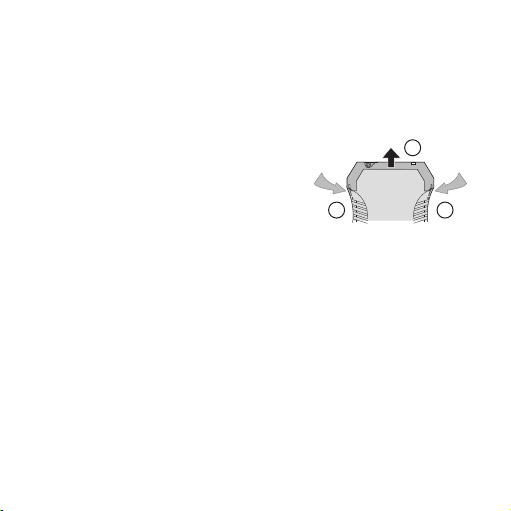
3.2 To open the module
Remove the connector. Disengage the locking mechanism by
lightly pressing the locks on both
sides of the housing 햲, remove
the upper part of the housing
and the electronics 햳.
1
2
1
Page 6

4
Input
24Vac/dc...70Vac/dc
70Vac/dc...140Vac/dc
140Vac/dc...210Vac/dc
210Vac/dc...260Vac/dc
Tri p
High Trip
Low Trip
Memory
Memory on
Memory off
Hysteresis
Hysteresis, small
Hysteresis, large
Input voltage
AC voltage
DC voltage
1 2 3 4 5 6 7 8
on
on
on
on
on
on
on
on
3.3 Settings
3.3.1 Table of settings options for 931S-V1R1D-MC1R
Page 7
5
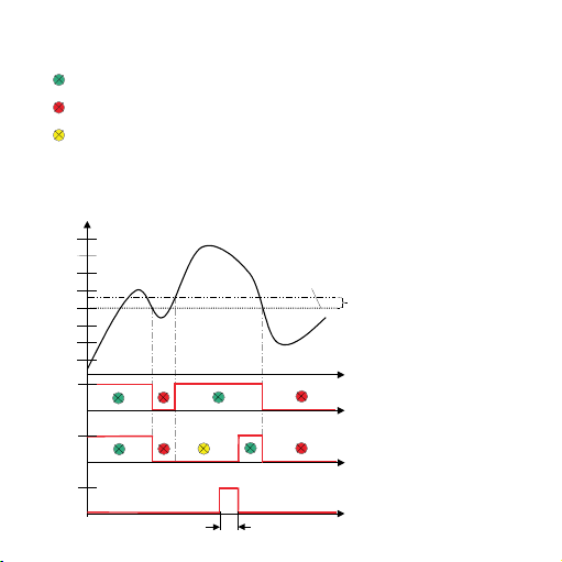
50%
100%
Input range
1
0
1
0
Output
1
0
min. 700ms
Reset
Alarm trip with setting Low Trip
(Closed-circuit current principle permanently set)
Operating point
Hysteresis
Times
Relay/Low Trip Memory off
Relay/Low Trip Memory on
Reset for output
4. Settings examples
4.1 Monitoring single-phase undervoltage with 931S-V1R1D-MC1R
No underflow of the setpoint value
Alarm status
The alarm status can be reset, because set-
point value was exceeded
Page 8

6
5. Electrical connection
5.1 Technical Data
Supply voltage 18 ... 30 Vdc / approx. 1 W
Operating temperature 0 °C ... + 55 °C
931S-V1R1D-MC1R
Terminal
1 + reset (18 Vdc...30 Vdc)
2 nc
3 – reset
4 nc
5 Input (24Vac/dc...260Vac/dc)
6 Input (24Vac/dc...260Vac/dc)
7 nc
8 nc
9 nc
10 Relay contact 11
11 Relay contact 12
12 Relay contact 14
Connection cross-section max. 2.5 mm
2
Multi-wire connection max. 1 mm
2
(two wires with the same cross-section)
Page 9

7
6. Dimensions in mm
7
17.5
92.4
Cross-connections
multiple devices
GND
for
90
24 Vdc
111.4
73.4 38
Page 10

8
7. Accessories
Designation Cat. No.
Plug-In Jumper, 2-pole, black 1492-CJLJ5-2-BL
Plug-In Jumper, 2-pole, red 1492-CJLJ5-2-R
Plug-In Jumper, 2-pole, blue 1492-CJLJ5-2-B
Plug-In Jumper, 2-pole, yellow 1492-CJLJ5-2
Marker Cat. No.
1492-M6X10
Power Supply
24 V DC Output
15 W 1606-XLP15E
30 W 1606-XLP30E
50 W 1606-XLP50E
100 W 1606-XLP100E
120 W (5 A) 1606-XLE120E
DIR 10000043408
(Version 00)
Page 11

9
1. Allgemeine Hinweise
Das Spannungsüberwachungsmodul der Reihe 931S-V1R1D-MC1R darf
nur von qualifizier tem Fachpersonal installiert werden. Erst nach der fachgerechten Installation darf das Gerät mit Hilfsenergie versorgt werden.
Während des Betriebs darf keine Bereichsumschaltung vorgenommen werden, da hierbei berührungsgefähr liche Teile offen liegen.
Die nationalen Vorschriften (z. B. für Deutschland DIN VDE 0100) bei der Installation und Auswahl der Zuleitungen müssen beachtet werden.
Bei Anwendungen mit hohen Isolationsspannungen ist auf genügend Abstand bzw. Isolation zu Nebengeräten und auf Berührungsschutz zu achten! Es sind generell Aderendhülsen mit Kunststoffkragen zu verwenden.
Bei Montage und Einstellarbeiten am 931S-V1R1D-MC1R VMR
1ph/3ph ist auf Schutzmaßnahmen gegen elektrostatische
Entladung (ESD) zu achten.
1.1 EMV-Hinweis
Während einer Störeinwirkung durch HF-Einstrahlung können
Abweichungen auftreten. Diese Störbeeinflussung kann durch
den Einbau des Betriebsmittels in ein schirmendes Gehäuse,
der Verwendung von geschirmten Leitungen oder Leitungsfiltern
reduziert werden.
ACHTUNGACHTUNGACHTUNGACHTUNG
Page 12

2. Funktionsbeschreibung
2.1 Spannungsüberwachungsmodul 931S-V1R1D-MC1R
Das Modul überwacht Spannungen in einphasigen Netzen
von 24Vac/dc bis 260Vac/dc. Dieser Spannungsbereich teilt
sich in 4 Einzelbereiche auf. Die Spannungsversorgung erfolgt
über den Überwachungseingang. Der Schaltausgang ist über
ein Relais mit Wechselkontakt realisiert. Das Gerät arbeitet
grundsätzlich im Ruhestromverfahren, d.h. das Relais ist im
Status OK angezogen und fällt bei einer Alarmmeldung ab. Der
Schaltpunkt wird mit einem Potentiometer eingestellt (unter der
Kunststofffrontscheibe angebracht).
Funktionen:
- High Trip: Relais schaltet bei Überschreitung der ein-
gestellten Schaltschwelle
- Low Trip: Relais schaltet bei Unterschreitung der ein-
gestellten Schaltschwelle
- Memory ein: Der Alarmzustand des Ausganges bleibt er-
halten und kann über einen internen Taster
oder externen Reseteingang zurückgesetzt
werden
- Memory aus: Der Alarmzustand wird nicht gespeichert
- Hysterese klein: Aus- und Einschaltverzögerung von 5V/8V
abhängig vom eingestellten Bereich
- Hysterese gross: Aus- und Einschaltverzögerung von
10V/16V abhängig vom eingestellten Bereich
10
Page 13

11
- AC-Spannung: Wechselspannungsmessung des Ein-
gangssignals
- DC-Spannung: Gleichspannungsmessung des Eingangs-
signals
3. Konfigurierung des Gerätes
3.1 Hilfsmittel
Zum Einstellen des Gerätes und zum Anschluss der Leitungen
an die Klemmen wird ein Schraubendreher mit einer Klingenbreite von 2,5 mm benötigt.
3.2 Gerät öffnen
Stecker abziehen. Durch leichten
Druck den Verschluss auf beiden
Seiten des Gehäuses entriegeln
햲, Gehäuseoberteil und Elektronik herausziehen 햳.
1
2
1
Page 14

Eingang
24Vac/dc...70Vac/dc
70Vac/dc...140Vac/dc
140Vac/dc...210Vac/dc
210Vac/dc...260Vac/dc
Tri p
High Trip
Low Trip
Speicher
Memory ein
Memory aus
Hysterese
Hysterese klein
Hysterese gross
Eingangsspannung
AC-Spannung
DC-Spannung
1 2 3 4 5 6 7 8
on
on
on
on
on
on
on
on
3.3 Einstellungen
3.3.1 Tabelle der Einstellmöglichkeiten für 931S-V1R1D-MC1R
12
Page 15

13
(Ruhestromprinzip fest eingestellt)
Schaltschwelle
50%
100%
Eingangsbereich
Hysterese
1
0
1
0
Ausgang
1
0
Zeit
min. 700ms
Reset
Alarmauslösung mit Einstellung Low Trip
Relais/Low Trip Memory aus
Relais/Low Trip Memory ein
Reset für Ausgang
4. Einstellbeispiele
4.1 Einphasige Unterspannungsüberwachung mit 931S-V1R1D-MC1R
keine Unterschreitung der Sollwertes
Alarmzustand
Alarmzustand lässt sich zurücksetzen,
da Sollwert überschritten wurde
Page 16

5. Der elektrische Anschluss
5.1 Technische Daten
Versorgungsspannung 18 ... 30 Vdc / ca. 1 W
Betriebstemperatur 0 °C ... + 55 °C
931S-V1R1D-MC1R
Klemme
1 + Reset (18Vdc...30Vdc)
2 nc
3 – Reset
4 nc
5 Eingang (24Vac/dc...260Vac/dc)
6 Eingang (24Vac/dc...260Vac/dc)
7 nc
8 nc
9 nc
10 Relaiskontakt 11
11 Relaiskontakt 12
12 Relaiskontakt 14
Anschlussquerschnitt max. 2,5 mm
2
Mehrleiteranschluss max. 1 mm
2
(zwei Leiter gleichen Querschnitts)
14
Page 17

6. Abmessungen in mm
15
17,5
92,4
111,4
73,4 38
90
Page 18

7. Zubehör
Bezeichnung Best.-Nr.
Querverbindung – 2,5 N/2 schwarz 1492-CJLJ5-2-BL
Querverbindung – 2,5 N/2 rot 1492-CJLJ5-2-R
Querverbindung – 2,5 N/2 blau 1492-CJLJ5-2-B
Querverbindung – 2,5 N/2 gelb 1492-CJLJ5-2
Marker Best.-Nr.
1492-M6X10
Power Supply
24 V DC Output
15 W 1606-XLP15E
30 W 1606-XLP30E
50 W 1606-XLP50E
100 W 1606-XLP100E
120 W (5 A) 1606-XLE120E
16
DIR 10000043408
(Version 00)
Page 19

17
1. Remarques générales
Le module de contrôle de tension de la gamme 931S-V1R1D-MC1R ne
doit être installé que par un personnel qualifié. L'équipement ne doit être
alimenté en énergie auxiliaire qu'après installation dans les règles de l'art.
Ne pas tenter de changer de plage pendant le fonctionnement, des pièces
dangereuses par contact direct sont en effet accessibles. Les prescriptions
nationales (p. ex. la norme DIN VDE 0100 pour l'Allemagne) doivent être
respectées lors de l'installation et du choix des conducteurs d'alimentation.
Pour les applications à grande tensions d'isolation, veiller à
un espace suffisant ou une isolation par rapport aux appareils voisin , ainsi
qu'à la protection contre les contacts ! Utiliser toujours des embouts à
collerette plastique.
Veuillez respecter les mesures de protection contre les décharges électrostatiques (pointes de tension) lors du montage et des
opérations de réglage sur 931S-V1R1D-MC1R VMR 1ph/3ph .
1.1 Remarque CEM
L'incidence des parasites par rayonnement HF peut conduire à
des écarts de mesure. Il est possible de réduire l'incidence de
ces parasites en intégrant l'équipement dans un boîtier blindé,
en utilisant des conducteurs écrantés ou des filtres de ligne.
ATTENTIONATTENTION
Page 20

18
2. Description du fonctionnement
2.1 Module de contrôle de tension 931S-V1R1D-MC1R
Ce module surveille les tensions des réseaux monophasés
de 24Vca/cc à 260Vca/cc. Cette plage de tension se divise en
4 plages individuelles. L'alimentation en tension s'effectue par
l'entrée contrôle. La sortie commutée est réalisée par un relais à
contact inverseur. L'appareil fonctionne toujours en mode
courant de repos, c.-à-d. que le relais est excité à l'état OK et
retombe sur message d'alarme. Le point de commutation se
règle à l'aide d'un potentiomètre (situé sous la face avant en
plastique).
Fonctions :
- Déclenchement haut :
Le relais commute sur dépassement du seuil réglé
- Déclenchement bas :
Le relais commute sur soupassement du seuil réglé
- Mémoire activée :
L'état d'alarme de la sortie est maintenu et peut
être réinitialisé par un bouton-poussoir interne ou
une entrée externe de réinitialisation
- Mémoire désactivée :
L'alarme n'est pas mémorisée
- Petit hystérésis :
Retard à l'ouverture et à la fermeture de 5V/8V selon la plage réglée
Page 21

19
- Grand hystérésis :
Retard à l'ouverture et à la fermeture de 10V/16V
selon la plage réglée
- Tension CA :
mesure de tension alternative du signal d'entrée
- Tension CC :
mesure de tension continue du signal d'entrée
3. Configuration de l'appareil
3.1 Outillage
Pour régler l'appareil et raccorder les conducteurs sur les bornes , il faut un tournevis plat de largeur 2,5 mm.
3.2 Ouverture de l'appareil
Débrancher le connecteur mâle.
En appuyant légèrement, déverrouiller le loquet des deux côtés
햲, sortir la partie supérieure du
boîtier et l'électronique 햳.
1
2
1
Page 22

20
Entrée
24Vca/cc...70Vca/cc
70Vca/cc...140Vca/cc
140Vca/cc...210Vca/cc
210Vca/cc...260Vca/cc
Déclenchement
Déclenchement haut
Déclenchement bas
Mémoire
Mémoire activée
Mémoire désactivée
Hystérésis
Petite hystérésis
Grande hystérésis
Tension d'entrée
Tension CA
Tension CC
1 2 3 4 5 6 7 8
on
on
on
on
on
on
on
on
3.3 Réglages
3.3.1 Tableau des réglages possibles du 931S-V1R1D-MC1R
Page 23

21
50%
100%
Plage d'entrée
1
0
1
0
Sortie
1
0
min. 700ms
Réinit.
Déclenchement d'alarme par réglage du déclenchement bas
(Sécurité positive fixée)
Seuil de commutation
Hystérésis
Temps
Relais/ mémoire
déclenchement bas désactivé
Relais/ mémoire
déclenchement bas activé
Réinitialisation de la sortie
4. Exemples de réglage
4.1 Contrôle de manque tension monophasée avec le 931S-V1R1D-MC1R
pas de soupassement de la consigne
Etat d'alarme
AL'alarme peut être réinitialisée car la
consigne a été dépassée
Page 24

22
5. Raccordement électrique
5.1 Caractéristiques techniques
Tension d’alimentation 18 ... 30 Vdc / env. 1 W
Température de service 0 °C ... + 55 °C
931S-V1R1D-MC1R
Borne
1 + Réinit. (18Vcc à 30Vcc)
2 nc
3 – Réinit
4 nc
5 Entrée (24Vca/cc à 260Vca/cc)
6 Entrée (24Vca/cc à 260Vca/cc)
7 nc
8 nc
9 nc
10 Contact relais 11
11 Contact relais 12
12 Contact relais 14
Section max. de raccordement 2.5 mm
2
Raccordement multifilaire max. 1 mm
2
(deux conducteurs de même section)
Page 25

23
6. Dimensions en mm
17,5
92,4
GND
Connexion
transversale
d’alimentation
en tension
24 Vdc
90
111,4
73,4 38
Page 26

24
7. Accessoires
Désignation Réf.
Connexion transversale – 2,5 N/2 noir 1492-CJLJ5-2-BL
Connexion transversale – 2,5 N/2 rouge 1492-CJLJ5-2-R
Connexion transversale – 2,5 N/2 bleu 1492-CJLJ5-2-B
Connexion transversale – 2,5 N/2 jaune 1492-CJLJ5-2
Marker Réf.
1492-M6X10
Power Supply
24 V DC Output
15 W 1606-XLP15E
30 W 1606-XLP30E
50 W 1606-XLP50E
100 W 1606-XLP100E
120 W (5 A) 1606-XLE120E
DIR 10000043408
(Version 00)
 Loading...