

Page 1
Installation Instructions 3
Beipackinformation 14
Notice d’utilisation 24
de
en
fr
DIR 10000043402
(Version 00)
Universal Thermocouple, 3 Way
931S-T9C2D-DC
10000043402
Page 2

Page 3

3
1. General instructions
• Disconnect power prior to installation
• Installation only by Qualified personnel
• Follow all applicable local and national electrical codes
• Due to potential hazardous voltages in close proximity, use a nonconductive tool and proper PPE when adjusting the potentiometers
on the front panel.
For applications with high isolation voltages, take measures to prevent
accidental contact and make sure that there is sufficient distance or insulation between adjacent devices!
Appropriate safety measures against electrostatic discharge
(ESD) should be taken during assembly and adjustment work on
the 931S-T9C2D-DC.
2. Application
The 3 Way Universal Thermocouple Conditioners 931S-T9C2D-DC are
used for galvanic isolation and conversion of thermoelement signals. Input
and output signals are factory set according to type or can be calibrated/
switched via DIP switches. It is not necessary to adjust the measurement
range. A +/- 5% variation can be achieved in the respective range by
connecting potentiometers for zero and span. The transmitted
measurement signal is linear to be measured temperature.
WARNINGWARNINGWARNINGWARNING
Page 4
4
3. Configuration
3.1 Equipment
A screwdriver with a width of 2.5 mm is required to adjust the unit and to
connect the wires to the terminals.
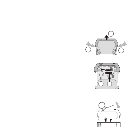
3.2 Opening the unit
Disconnect the plugs. Disengage the top part of
the housing by carefully pressing the latches on
both sides (1). Pull out the top part of the housing and the electronics section until they unlock
(2).
3.3 Settings
Set input and output ranges, minimum input
values and measuring span via the DIP switches
SW1 and SW2 according to the following tables.
When activating variable setting SW 1/8 of the
span or offset, it is possible to make additional
adjustments via front potentiometers span and
offset, accessible below cover (3).
1
1
2
Zero
Span
SW2
SW1
3
Page 5
5
Selecting the thermocouple
SW1
Type 1 2 3
K 111
J 011
T 101
E 001
N 110
R 010
S 100
B 000
Selecting the minimum temperature
SW1
min 4567
0º C 1111
–10º C 1 1 1 0
–20º C 1 1 0 1
–30º C 1 1 0 0
–40º C 1 0 1 1
–50º C 1 0 1 0
–100º C 1 0 0 1
–150º C 1 0 0 0
–200º C 0 1 1 1
+50º C 0 1 1 0
+100º C 0 1 0 1
Page 6
6
SW1
min 4567
+150º C 0 1 0 0
+200º C 0 0 1 1
+250º C 0 0 1 0
+500º C 0 0 0 1
Special range 0 0 0 0
Activating the manual fine adjustment
SW1
manual calibration 8
off 0
on 1
1 = on
0 = off
Page 7

7
Selecting the temperature span
SW2
Span 12345
100º C 11111
150º C 11110
200º C 11101
250º C 11100
300º C 11011
350º C 11010
400º C 11001
450º C 11000
500º C 10111
550º C 10110
600º C 10101
650º C 10100
700º C 10011
750º C 10010
800º C 10001
850º C 10000
900º C 01111
950º C 01110
1000º C 01101
1050º C 01100
1100º C 01011
1150º C 01010
1200º C 01001
1250º C 01000
Page 8
8
SW2
Span 12345
1300º C 00111
1350º C 00110
1400º C 00101
1450º C 00100
1500º C 00011
1600º C 00010
1700º C 00001
1800º C 00000
Selecting the output
SW2
Output 6 7
0…10 V 1 0
0…20 mA 0 0
4…20 mA 0 1
Activating the filter function
SW2
Filter 8
off 0
on 1
1 = on
0 = off
Page 9

Should a temperature measurement range be selected that is larger than
the specified range of the thermocouple used, then the module sets itself
to the maximum specified range:
Type K –200º C … +1372º C
Type J –200º C … +1200º C
Type T –200º C … +400º C
Type E –200º C … +1000º C
Type N –200º C … +1300º C
Type R –50º C … +1760º C
Type S –50º C … +1760º C
Type B +50º C … +1820º C
The voltage output and the combined current output (0…20 mA and
4…20 mA) are routed from two separate, calibrated connections.
The output selected via the DIP switch, is the only output that is calibrated.
9
Page 10
10
4. Mounting
The signal conditioners are mounted on standard TS 35 rails.
5. Electrical connection
5.1 Technical Data
Supply voltage 18 ... 30 Vdc/approx. 1 W
Operating temperature 0 °C ... +55 °C
Voltage supply via cross-connections. Operating carrying capacity of crossconnection 2 A
A
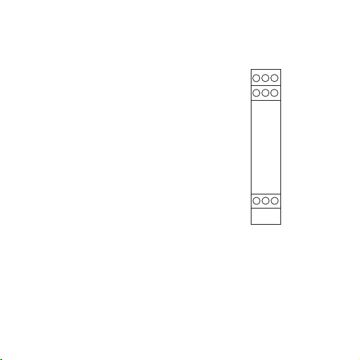
Terminal assignments
1 Thermo +
2 not assigned
3 Thermo –
7 Output + 0/4…20 mA
8 Output + 0…10 V
9 Output 0 V
10 Power supply + 24 Vdc (cross connected)
11 Power supply GND (cross connected)
12 not assigned
Wire cross-section max. 2.5 mm
2
Multi-wire conncection max. 1 mm
2
(two wires with same cross-section)
Klemmenbelegung
1 Eingang + > 5 mA
2 Eingang + ≤ 500 mV / ≤ 5 mA
3 Eingang + > 500 mV
4 Eingang -
5 Ausgang +
6 Ausgang -
7 Versorgungsspannung
8 Versorgungsspannung
nschlußquerschnitt max. 2,5 mm
Mehrleiteranschluß max. 1 mm
(zwei Leiter gleichen Querschnitts)
2
2
10
78
1
12
11
9
3
2
Page 11

11
92.4
90
38
111.4
73.4
17.5
mm
Cross-connections
for multiple devices
GND
24 Vdc
6. Dimensions
Page 12

7. Accessories
Designation Cat. No.
Plug-In Jumper, 2-pole, yellow 1492-CJLJ5-2
Plug-In Jumper, 2-pole, red 1492-CJLJ5-2-R
Plug-In Jumper, 2-pole, blue 1492-CJLJ5-2-B
Plug-In Jumper, 2-pole, black 1492-CJLJ5-2-BL
Marker Cat. No.
1492-M5X10
Power Supply
24 V DC Output
15 W 1606-XLP15E
30 W 1606-XLP30E
50 W 1606-XLP50E
100 W 1606-XLP100E
120 W (5 A) 1606-XLE120E
12
Page 13

13
DIR 10000043402
(Version 00)
DIR 10000043402
(Version 00)
8. UL Class 1, Division 2 Markings
for selected Signal Conditioners
A. “This equipment is suitable for use in Class I, Division 2, Groups A, B,
C and D hazardous locations or non hazardous locations only or the
equivalent.”
B. “WARNING: EXPLOSION HAZARD - Substitution of components may
impair suitability for use in Class I, Division 2 environments.”
C. “WARNING: EXPLOSION HAZARD - The area must be known to be
non hazardous before servicing/replacing the unit and before installing
or removing I/O wiring.”
D. “WARNING: EXPLOSION HAZARD - Do Not disconnect equipment
unless power has been disconnected and the area is known to be non
hazardous.”
The warning references on this side have only validity for modules with a
UL Class I, Division 2 permission.
WARNINGWARNING
Page 14

1. Allgemeine Hinweise
Die Analogsignaltrenner der Reihe 931S-T9C2D-DC dürfen nur von qualifizier tem Fachpersonal installiert werden. Erst nach der fachgerechten Installation darf das Gerät mit Hilfsenergie versorgt werden. Während des Betriebs darf keine Bereichsumschaltung vorgenommen werden, da hierbei
berührungsgefähr liche Teile offen liegen. Ein Feinabgleich über die frontseitigen Potis darf nur mit einem Schraubendreher erfolgen, der sicher gegen
die an den Eingang gelegte Spannung isoliert ist! Die nationalen Vorschriften (z. B. für Deutschland DIN VDE 0100) bei der Installation und Auswahl
der Zuleitungen müssen beachtet werden.
Bei Anwendungen mit hohen Isolationsspannungen ist auf genügend Abstand bzw. Isolation zu benachbarten Geräten und auf Berührungsschutz
zu achten!
Bei Montage und Einstellarbeiten am 931S-T9C2D-DC ist auf
Schutzmaßnahmen gegen elektrostatische Entladung (ESD) zu
achten.
2. Anwendung
Die Analogsignaltrenner dienen zur galvani schen Trennung und Umwandlung von Thermoelementsignalen. Ein- und Ausgangssignal sind über DIPSchalter kalibriert umschaltbar. Ein Nachjustieren der voreinstellbaren Meßbereiche ist nicht erforderlich. Durch Zuschaltung von Potentiometern für
Zero und Span kann im jeweiligen Bereich +/- 5% variiert werden. Das Ausgangssignal ist linear zur gemessenen Temperatur.
14
ACHTUNGACHTUNGACHTUNGACHTUNG
Page 15

3. Konfigurierung des Gerätes
3.1 Hilfsmittel
Zum Einstellen des Gerätes und zum Anschluß der Leitungen an die
Klemmen wird ein Schraubendreher mit einer Klingenbreite von 2,5 mm
benötigt.
3.2 Gerät öffnen
Stecker abziehen. Durch leichten Druck den
Verschluß auf beiden Seiten des Gehäuses
entriegeln (1), Gehäuseoberteil und Elektronik
herausziehen (2).
3.3 Einstellungen
Einstellung von Ein- und Ausgangsbereich, mini malen Eingangsgröße und Meßspanne mittels der
DIP-Schalter SW1 und SW2 gemäß nachfolgender
Tabellen.
Zum Feinabgleich von Verstärkung und Offset
können die frontseitig unterhalb der Abdeckung (3)
zugänglichen Potis Span (Verstärkung) bzw. Zero (Offset)
mit Schalter SW1/8 aktiviert werden.
1
1
2
Zero
Span
SW2
SW1
3
15
Page 16

Auswahl des Thermoelements
SW1
Typ123
K 111
J 011
T 101
E 001
N 110
R 010
S 100
B 000
Auswahl der minimalen Temperatur
SW1
min 4567
0º C 1111
–10º C 1 1 1 0
–20º C 1 1 0 1
–30º C 1 1 0 0
–40º C 1 0 1 1
–50º C 1 0 1 0
–100º C 1 0 0 1
–150º C 1 0 0 0
–200º C 0 1 1 1
+50º C 0 1 1 0
+100º C 0 1 0 1
16
Page 17

SW1
min 4567
+150º C 0 1 0 0
+200º C 0 0 1 1
+250º C 0 0 1 0
+500º C 0 0 0 1
Sonderbereich 0 0 0 0
Einschalten des manuellen Feinabgleichs
SW1
man. Abgl. 8
aus 0
ein 1
1 = ein
0 = aus
17
Page 18

Auswahl der Temperaturspanne
SW2
Spanne 12345
100º C 11111
150º C 11110
200º C 11101
250º C 11100
300º C 11011
350º C 11010
400º C 11001
450º C 11000
500º C 10111
550º C 10110
600º C 10101
650º C 10100
700º C 10011
750º C 10010
800º C 10001
850º C 10000
900º C 01111
950º C 01110
1000º C 01101
1050º C 01100
1100º C 01011
1150º C 01010
1200º C 01001
1250º C 01000
18
Page 19

SW2
Spanne 12345
1300º C 00111
1350º C 00110
1400º C 00101
1450º C 00100
1500º C 00011
1600º C 00010
1700º C 00001
1800º C 00000
Auswahl des Ausgangs
SW2
Ausgang 6 7
0…10 V 1 0
0…20 mA 0 0
4…20 mA 0 1
Einschalten der Filterfunktion
SW2
Filter 8
aus 0
ein 1
1 = ein
0 = aus
19
Page 20

Wird ein Temperaturmeßbereich selektiert, der größer als der spezifizierte
Bereich des verwendeten Thermoelementtyps ist, so stellt sich der Baustein auf den maximal spezifizierten Bereich ein:
Typ K –200º C … +1372º C
Typ J –200º C … +1200º C
Typ T –200º C … +400º C
Typ E –200º C … +1000º C
Typ N –200º C … +1300º C
Typ R –50º C … +1760º C
Typ S –50º C … +1760º C
Typ B +50º C … +1820º C
Der Spannungsausgang und der kombinierte Stromausgang (0…20 mA
und 4…20 mA) sind auf zwei separate, kalibrierte
Anschlüsse herausgeführt. Kalibriert ist nur derjenige Ausgang, der über den DIP-Schalter ausgewählt wird.
20
Page 21

4. Montage
Die Analogsignaltrenner werden auf TS 35 Normschienen aufgerastet.
5. Der elektrische Anschluß
5.1 Technische Daten
Versorgungsspannung 18 ... 30 Vdc/ca. 1 W
Betriebstemperatur 0 °C ... +55 °C
Spannungsversorgung ausgeführt über Querverbindungen
Stromtragfähigkeit der Querverbindung ≤ 2 A
A
Klemmenbelegung
1 Thermo +
2 nicht belegt
3 Thermo –
7 Ausgang + 0/4…20 mA
8 Ausgang + 0…10 V
9 Ausgang 0 V
10 Versorgungsspannung + 24 Vdc (querverbunden)
11 Versorgungsspannung GND (querverbunden)
12 nicht belegt
Anschlußquerschnitt max. 2,5 mm
2
Mehrleiteranschluß max. 1 mm
2
(zwei Leiter gleichen Querschnitts)
21
Klemmenbelegung
1 Eingang + > 5 mA
2 Eingang + ≤ 500 mV / ≤ 5 mA
3 Eingang + > 500 mV
4 Eingang -
5 Ausgang +
6 Ausgang -
7 Versorgungsspannung
8 Versorgungsspannung
nschlußquerschnitt max. 2,5 mm
Mehrleiteranschluß max. 1 mm
(zwei Leiter gleichen Querschnitts)
10
11
78
2
1
2
2
12
9
3
Page 22

Querverbindungen für
Spannungsversorgung
6. Abmessungen
22
92,4
90
38
111,4
73,4
17,5
mm
GND
24 Vdc
Page 23

7. Zubehör
Bezeichnung Best.-Nr.
Querverbindung – 2,5 N/2 gelb 1492-CJLJ5-2
Querverbindung – 2,5 N/2 rot 1492-CJLJ5-2-R
Querverbindung – 2,5 N/2 blau 1492-CJLJ5-2-B
Querverbindung – 2,5 N/2 schwarz 1492-CJLJ5-2-BL
Marker Best.-Nr.
1492-M5X10
Power Supply
24 V DC Output
15 W 1606-XLP15E
30 W 1606-XLP30E
50 W 1606-XLP50E
100 W 1606-XLP100E
120 W (5 A) 1606-XLE120E
23
DIR 10000043402
(Version 00)
DIR 10000043402
(Version 00)
Page 24

1. Indications générales
Les séparateurs de la série 931S-T9C2D-DC ne doivent être installés que
par du personnel qualifié. L'alimentation électrique de l'appareil ne doit être
réalisée qu'après une installation con forme aux prescrip tions. Ne pas changer de plage pendant le fonctionnement, au risque de dé couvrir des pièces
au contact dangereux. Un réglage fin avec les potentiomètres situés en face
avant doit être effectué unique ment avec un tournevis correcte ment isolé
contre la tension appliquée en entrée ! Les directives nationales en vigeur
doivent être prises en compte pour l’installation et la sélection des câbles.
En cas d'utilisation avec des tensions d’isolement élevées, veiller à avoir une
distance ou une isolation suffisante par rapport aux appareils voisins et respecter la protection contre les contacts!
Lors du montage et des opérations de réglage du séparateur de
signaux analogiques, observer les mesures de protection contre
les décharges électrostatiques.
2. Utilisation
Les séparateurs analogiques de signal sont destinés à séparation galvanique et à la conversion des signaux de thermocouples. Selon le modèle le
signal d’entrée/sortie est fixé ou commutable calibré par commutateur DIP.
Il n’est pas nécessaire d’ajuster ultérieurement les plages de mesure préréglées. Par ajout de potentiomètres d’ajustage de zéro et de l’échelle, possibilité de variation de +/- 5% dans chaque plage. La transmission du signal
de mesure est linéaire.
24
ATTENTIONATTENTION
Page 25

3. Configuration
3.1 Accessoires
Pour raccorder les conducteurs aux bornes il faut avoir un tournevis avec
une étendue de 2,5 mm.
3.2 Ouverture de l’appareil
Retirer les fiches. Presser légèrement sur les
deux languettes (1) pour déverrouiller la partie
supérieure du boîtier. On peut ainsi sortir la
partie supé rieure et l’électronique jusqu’à ce
qu’elles s’enclenchent (2).
3.3 Réglages
Les tableaux suivants donnet les réglages des plages d’entrée et de sortie, des grandeurs d’entrée et
d’étendue de mesure minimales au moyen des boîtiers DIP SW1 et SW2.
En sélectionnant un réglage variable SW 1/8 de gain
ou de décalage, réglage supplémentaire à l’aide des
potentiomètres Span (gain) ou Zero (décalage)
accessibles en face avant en dessous du capot (3).
1
1
2
Zero
Span
SW2
SW1
3
25
Page 26

Sélection du thermocouple
SW1
TYPE 1 2 3
K 111
J 011
T 101
E 001
N 110
R 010
S 100
B 000
Sélection de la température minimale
SW1
min 4567
0º C 1111
–10º C 1 1 1 0
–20º C 1 1 0 1
–30º C 1 1 0 0
–40º C 1 0 1 1
–50º C 1 0 1 0
–100º C 1 0 0 1
–150º C 1 0 0 0
–200º C 0 1 1 1
+50º C 0 1 1 0
+100º C 0 1 0 1
26
Page 27

SW1
min 4567
+150º C 0 1 0 0
+200º C 0 0 1 1
+250º C 0 0 1 0
+500º C 0 0 0 1
Plage spéciale 0 0 0 0
Activation du réglage manuel fin
SW1
réglage man. 8
arrêt 0
marche 1
1 = activé
0 = désactivé
27
Page 28

Sélection de l’étendue de température
SW2
Etendue 12345
100º C 11111
150º C 11110
200º C 11101
250º C 11100
300º C 11011
350º C 11010
400º C 11001
450º C 11000
500º C 10111
550º C 10110
600º C 10101
650º C 10100
700º C 10011
750º C 10010
800º C 10001
850º C 10000
900º C 01111
950º C 01110
1000º C 01101
1050º C 01100
1100º C 01011
1150º C 01010
1200º C 01001
1250º C 01000
28
Page 29

SW2
Etendue 12345
1300º C 00111
1350º C 00110
1400º C 00101
1450º C 00100
1500º C 00011
1600º C 00010
1700º C 00001
1800º C 00000
Sélection de la sortie
SW2
Sortie 6 7
0…10 V 1 0
0…20 mA 0 0
4…20 mA 0 1
Activation de la fonction de filtrage
SW2
Filtre 8
arrêt 0
marche 1
1 = activé
0 = désactivé
29
Page 30

Si une plage de mesure de température est sélectionnée supérieure à la
plage spécifiée pour le type de thermocouple utilisé le module se règle sur
la plage maximale spécifée :
Type K –200º C … +1372º C
Type J –200º C … +1200º C
Type T –200º C … +400º C
Type E –200º C … +1000º C
Type N –200º C … +1300º C
Type R –50º C … +1760º C
Type S –50º C … +1760º C
Type B +50º C … +1820º C
La sortie tension et la sortie courant combinée (0…20 mA et 4…20 mA)
sont délivrées sur deux bornes calibrées distinctes.
Seule la sortie sélectionnée par le commutateur DIP est calibrée.
30
Page 31

4. Montage
Les séparateurs sont encliquetés sur des rails de norme TS 35.
5. Le raccordement électrique
5.1 Caractéristiques techniques
Tension d’alimentation 18 ... 30 Vdc/env. 1 W
Température de service 0 °C ... +55 °C
Alimentation en tension sortie sur connexions transversales (max. 2 A)
A
Brochage
1 Thermo +
2 non connectée
3 Thermo –
7 Sortie + 0/4…20 mA
8 Sortie + 0…10 V
9 Sortie 0 V
10 Alimentation + 24 Vcc
(connexion transversale)
11 Alimentation GND
(connexion transversale)
12 non connectée
Section raccordement maxi. 2,5 mm
2
Raccordement multibrins maxi. 1 mm
2
(deux fils de même section)
31
Klemmenbelegung
1 Eingang + > 5 mA
2 Eingang + ≤ 500 mV / ≤ 5 mA
3 Eingang + > 500 mV
4 Eingang -
5 Ausgang +
6 Ausgang -
7 Versorgungsspannung
8 Versorgungsspannung
nschlußquerschnitt max. 2,5 mm
Mehrleiteranschluß max. 1 mm
(zwei Leiter gleichen Querschnitts)
10
11
78
2
1
2
2
12
9
3
Page 32

6. Dimensions
32
Connexion
transversale d’alimenta-
tion en tension
92,4
90
38
111,4
73,4
17,5
mm
GND
24 Vdc
Page 33

7. Accessoires
Désignation Réf.
Connexion transversale – 2,5 N/2 jaune 1492-CJLJ5-2
Connexion transversale – 2,5 N/2 rouge 1492-CJLJ5-2-R
Connexion transversale – 2,5 N/2 bleu 1492-CJLJ5-2-B
Connexion transversale – 2,5 N/2 noir 1492-CJLJ5-2-BL
Marker Réf.
1492-M5X10
Power Supply
24 V DC Output
15 W 1606-XLP15E
30 W 1606-XLP30E
50 W 1606-XLP50E
100 W 1606-XLP100E
120 W (5 A) 1606-XLE120E
33
DIR 10000043402
(Version 00)
DIR 10000043402
(Version 00)
 Loading...