

Page 1
Installation Instructions 3
Beipackinformation 14
Notice d’utilisation 25
de
en
fr
DIR 10000043401
(Version 00)
Active Converter, 3 Way, RTD
931S-P1C2D-DC
10000043401
Page 2

Page 3

3
1. General instructions
• Disconnect power prior to installation
• Installation only by Qualified personnel
• Follow all applicable local and national electrical codes
• Due to potential hazardous voltages in close proximity, use a nonconductive tool and proper PPE when adjusting the potentiometers
on the front panel.
Please observe that applications with high insulation voltages require
sufficient space or insulation to adjoining devices.
Protective measures must be taken against electrostatic
discharges (ESD) when mounting and setting 931S-P1C2D-DC.
2. Application
RTD 3 Way Active Converters 931S-P1C2D-DC are used for galvanic
isolation and conversion of temperature, resistance and potentiometer
signals. Input and output signals are calibrated switch selectable via
DIP switches. It is not necessary to adjust the pre-settable measurement
ranges. A +/- 12.5 % variation can be achieved in the respective range by
switching in potentiometers for zero and span. The analog signal is linear
to the temperature and to the resistance or to the potentiometer setting.
WARNINGWARNING
Page 4
4
3. Configuring the device
3.1 Tools
A screwdriver with a 2.5 mm blade is required to set the device,
and to connect the conductors to the terminals.
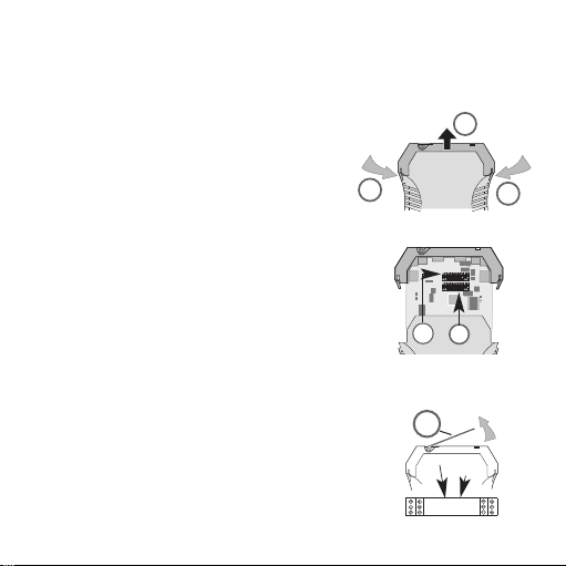
3.2 Open the device
Remove the connector Press the lock lightly
on both sides of the housing to unlock it (1),
remove the upper part of the housing and the
electronics (2).
3.3 Settings
Set input and output ranges, minimum input
values and measuring span via the DIP switches
SW1 and SW2 according to the following tables.
The potentiometers Span (gain) and Zero (offset)
can be activated by the switch SW1/8, accessible
from the front below the cover (3), to finely
calibrate the gain and offset
1
1
2
Zero
Span
SW2
SW1
3
Page 5

5
3.3.1 SWITCH SETTINGS
Selecting the input
SW 1
Input Input 1 2 3
PT100 2-wire PT1000 2-wire 1 1 1
PT100 3-wire PT1000 3-wire 0 1 1
PT100 4-wire PT1000 4-wire 1 0 1
R 2-wire R 2-wire 0 0 1
NI100 2-wire NI1000 2-wire 1 1 0
NI100 3-wire NI1000 3-wire 0 1 0
NI100 4-wire NI1000 4-wire 1 0 0
Potentiometer Potentiometer 0 0 0
Selecting the minimum input value
SW 1
min Rmin Rmin Potimin 4567
0º C 0 Ω 0 Ω 0%1111
–10º C 10 Ω 100 Ω 10% 1110
–20º C 20 Ω 200 Ω 20% 1101
–25º C 25 Ω 250 Ω 25% 1100
–30º C 30 Ω 300 Ω 30% 1011
–40º C 40 Ω 400 Ω 40% 1010
–50º C 50 Ω 500 Ω 50% 1001
–60º C 60 Ω 600 Ω 60% 1000
–70º C 70 Ω 700 Ω 70% 0111
–80º C 80 Ω 800 Ω 80% 0110
–90º C 90 Ω 900 Ω 0101
Page 6

6
SW 1
min Rmin Rmin Potimin 4567
–100º C 100 Ω 1000 Ω 0 1 0 0
–150 °C 150 Ω 1500 Ω 0 0 1 1
–200 °C 200 Ω 2000 Ω 0 0 1 0
Special range 0 0 0 0
Activating the manual fine calibration
SW 1
man. Cal. 8
on 0
off 1
1 = on
0 = off
Page 7

7
Selecting the measuring span
SW 2
T R R Poti12345
40K 20 Ω 200 Ω 20% 11111
50K 25 Ω 250 Ω 25% 11110
60K 30 Ω 300 Ω 30% 11101
70K 35 Ω 350 Ω 35% 11100
80K 40 Ω 400 Ω 40% 11011
90K 45 Ω 450 Ω 45% 11010
100K 50 Ω 500 Ω 50% 11001
110K 55 Ω 550 Ω 55% 11000
120K 60 Ω 600 Ω 60% 10111
125K 62,5 Ω 625 Ω 62,5% 10110
130K 65 Ω 650 Ω 65% 10101
140K 70 Ω 700 Ω 70% 10100
150K 75 Ω 750 Ω 75% 10011
160K 80 Ω 800 Ω 80% 10010
170K 85 Ω 850 Ω 85% 10001
180K 90 Ω 900 Ω 90% 10000
190K 95 Ω 950 Ω 95% 01111
200K 100 Ω 1000 Ω 100% 01110
250K 125 Ω 1250 Ω – 01101
300K 150 Ω 1500 Ω – 01100
350K 175 Ω 1750 Ω – 01011
400K 200 Ω 2000 Ω – 01010
450K 225 Ω 2250 Ω – 01001
500K 250 Ω 2500 Ω – 01000
550K 275 Ω 2750 Ω – 00111
Page 8

8
SW 2
T R R Poti12345
550K 275 Ω 2750 Ω – 00111
600K 300 Ω 3000 Ω – 00110
650K 325 Ω 3250 Ω – 00101
700K 350 Ω 3500 Ω – 00100
750K 375 Ω 3750 Ω – 00011
800K 400 Ω 4000 Ω – 00010
850K 425 Ω 4250 Ω – 00001
900K 450 Ω 4500 Ω – 00000
Selecting the output
SW 2
Output 6 7
0…10 V 1 0
0…20 mA 0 0
4…20 mA 0 1
Selecting the step response time
SW 2
Step response 8
slow 1
quick (less exact measuring) 0
1 = on
0 = off
Page 9
9
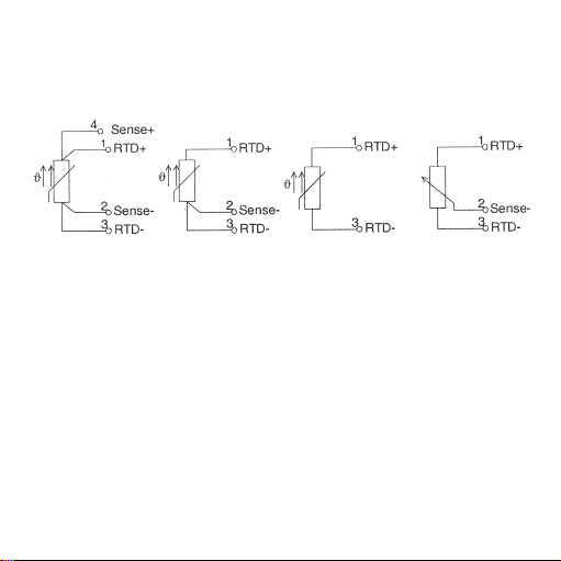
3.4 Terminal assignment of the sensors
Terminal assignment for 2-, 3-, 4-wires and potentiometers.
4-wire 3-wire 2-wire Potentiometer
Page 10
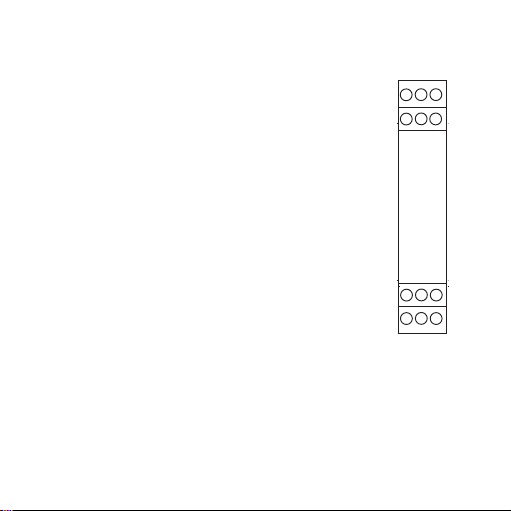
4. Mounting
The signal conditioners are mounted on standard TS 35 rails.
5. The electrical connection
Terminal assignment
1 input RTD +
2 input –
3 input RTD –
4 input sense +
5 not assigned
6 not assigned
7 output 0/4…20 mA
8 output 0…10 V
9 output GND
10 Supply voltage + 24 Vdc (cross-connected)
11 Supply voltage 0 V (cross-connected)
12 not assigned
Connection cross-section max. 2,5 mm
2
Multi-wire connection max. 1 mm
2
(two wires with the same cross-section)
5.1 Technical Data
Supply voltage 18 ... 30 Vdc/approx. 1 W
Operating temperature 0 °C ... +55 °C
Voltage supply via cross-connections
Current carrying capacity of the cross-connection 2 A
10
10
78
1
4
12
11
9
3
2
6
5
Page 11
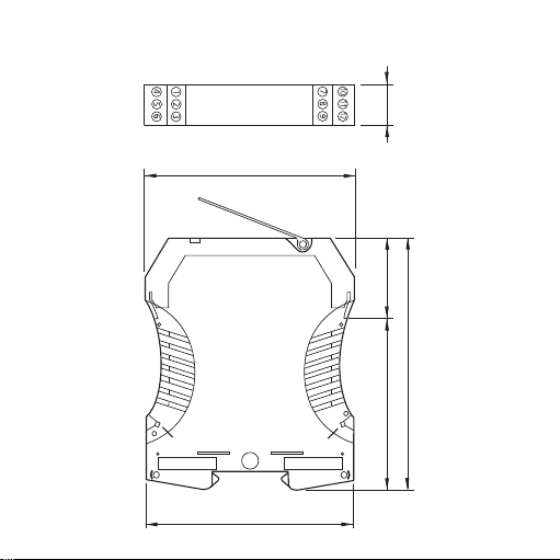
6. Dimensions in mm
92.4
90
111.4
73.4 38
17.5
Cross-connections
for
linking power to
multiple devices
GND
24 Vdc
11
Page 12

7. Accessories
Designation Cat. No.
Plug-In Jumper, 2-pole, yellow 1492-CJLJ5-2
Plug-In Jumper, 2-pole, red 1492-CJLJ5-2-R
Plug-In Jumper, 2-pole, blue 1492-CJLJ5-2-B
Plug-In Jumper, 2-pole, black 1492-CJLJ5-2-BL
Marker Cat. No.
1492-M5X10
Power Supply
24 V DC Output
15 W 1606-XLP15E
30 W 1606-XLP30E
50 W 1606-XLP50E
100 W 1606-XLP100E
120 W (5 A) 1606-XLE120E
12
Page 13

13
DIR 10000043401
(Version 00)
8. UL Class 1, Division 2 Markings
for selected Signal Conditioners
A. “This equipment is suitable for use in Class I, Division 2, Groups A, B,
C and D hazardous locations or non hazardous locations only or the
equivalent.”
B. “WARNING: EXPLOSION HAZARD - Substitution of components may
impair suitability for use in Class I, Division 2 environments.”
C. “WARNING: EXPLOSION HAZARD - The area must be known to be
non hazardous before servicing/replacing the unit and before installing
or removing I/O wiring.”
D. “WARNING: EXPLOSION HAZARD - Do Not disconnect equipment
unless power has been disconnected and the area is known to be non
hazardous.”
The warning references on this side have only validity for modules with a
UL Class I, Devision 2 permission.
WARNINGWARNING
Page 14

1. Allgemeine Hinweise
Die Analogsignaltrenner der Reihe 931S-P1C2D-DC dürfen nur von qualifizier tem Fachpersonal installiert werden. Erst nach der fachgerechten Installation darf das Gerät mit Hilfsenergie versorgt werden. Während des Betriebs darf keine Bereichsumschaltung vorgenommen werden, da hierbei
berührungsgefähr liche Teile offen liegen. Ein Feinabgleich über die frontseitigen Potis darf nur mit einem Schraubendreher erfolgen, der sicher gegen
die an den Eingang gelegte Spannung isoliert ist! Die nationalen Vorschriften (z. B. für Deutschland DIN VDE 0100) bei der Installation und Auswahl
der Zuleitungen müssen beachtet werden.
Bei Anwendungen mit hohen Isolationsspannungen ist auf genügend Abstand bzw. Isolation zu Nebengeräten und auf Berührungsschutz zu achten!
Bei Montage und Einstellarbeiten am 931S-P1C2D-DC ist auf Schutzmaßnahmen gegen elektrostatische Entladung (ESD) zu achten.
2. Anwendung
Die Analogsignaltrenner dienen zur galvani schen Trennung und Umwandlung von Temperatur-, Widerstands- und Potentiometersignalen. Ein- und
Aus gangssignal sind über DIP-Schalter kalibriert umschaltbar. Ein Nach justieren der voreinstellbaren Messbereiche ist nicht erforderlich. Durch
Zuschaltung von Potentiometern für Zero und Span kann im jeweiligen
Bereich +/- 12,5 % variiert werden. Das Ausgangssignal ist linear zur
Temperatur bzw. zum Widerstand oder zur Potentiometerstellung.
14
ACHTUNGACHTUNG
Page 15

3. Konfigurierung des Gerätes
3.1 Hilfsmittel
Zum Einstellen des Gerätes und zum Anschluss der Leitungen an die
Klemmen wird ein Schraubendreher mit einer Klingenbreite von 2,5 mm
benötigt.
3.2 Gerät öffnen
Stecker abziehen. Durch leichten Druck den
Verschluss auf beiden Seiten des Gehäuses
entriegeln (1), Gehäuseoberteil und Elektronik
herausziehen (2).
3.3 Einstellungen
Einstellung von Ein- und Ausgangsbereich, minimalen Eingangsgröße und Messspanne mittels der
DIP-Schalter SW1 und SW2 gemäß nachfolgender
Tabellen.
Zum Feinabgleich von Verstärkung und Offset
können die frontseitig unterhalb der Abdeckung (3)
zugänglichen Potis Span (Verstärkung) bzw. Zero
(Offset) mit Schalter SW1/8 aktiviert werden.
1
1
2
Zero
Span
SW2
SW1
3
15
Page 16

3.3.1 SWITCH SETTINGS
16
Auswahl des Eingangs
SW 1
Eingang Eingang 1 2 3
PT100 2-Leiter PT1000 2-Leiter 1 1 1
PT100 3-Leiter PT1000 3-Leiter 0 1 1
PT100 4-Leiter PT1000 4-Leiter 1 0 1
R 2-Leiter R 2-Leiter 0 0 1
NI100 2-Leiter NI1000 2-Leiter 1 1 0
NI100 3-Leiter NI1000 3-Leiter 0 1 0
NI100 4-Leiter NI1000 4-Leiter 1 0 0
Potentiometer Potentiometer 0 0 0
Auswahl der minimalen Eingangsgröße
SW 1
min Rmin Rmin Potimin 4567
0º C 0 Ω 0 Ω 0%1111
–10º C 10 Ω 100 Ω 10% 1110
–20º C 20 Ω 200 Ω 20% 1101
–25º C 25 Ω 250 Ω 25% 1100
–30º C 30 Ω 300 Ω 30% 1011
–40º C 40 Ω 400 Ω 40% 1010
–50º C 50 Ω 500 Ω 50% 1001
–60º C 60 Ω 600 Ω 60% 1000
–70º C 70 Ω 700 Ω 70% 0111
–80º C 80 Ω 800 Ω 80% 0110
–90º C 90 Ω 900 Ω 0101
Page 17

SW 1
min Rmin Rmin Potimin 4567
–100º C 100 Ω 1000 Ω 0 1 0 0
–150 °C 150 Ω 1500 Ω 0 0 1 1
–200 °C 200 Ω 2000 Ω 0 0 1 0
Sonderbereich 0 0 0 0
Einschalten des manuellen Feinabgleichs
SW 1
man. Abgl. 8
aus 0
ein 1
1 = ein
0 = aus
17
Page 18

Auswahl der Messspanne
SW 2
T R R Poti12345
40K 20 Ω 200 Ω 20% 11111
50K 25 Ω 250 Ω 25% 11110
60K 30 Ω 300 Ω 30% 11101
70K 35 Ω 350 Ω 35% 11100
80K 40 Ω 400 Ω 40% 11011
90K 45 Ω 450 Ω 45% 11010
100K 50 Ω 500 Ω 50% 11001
110K 55 Ω 550 Ω 55% 11000
120K 60 Ω 600 Ω 60% 10111
125K 62,5 Ω 625 Ω 62,5% 10110
130K 65 Ω 650 Ω 65% 10101
140K 70 Ω 700 Ω 70% 10100
150K 75 Ω 750 Ω 75% 10011
160K 80 Ω 800 Ω 80% 10010
170K 85 Ω 850 Ω 85% 10001
180K 90 Ω 900 Ω 90% 10000
190K 95 Ω 950 Ω 95% 01111
200K 100 Ω 1000 Ω 100% 01110
250K 125 Ω 1250 Ω – 01101
300K 150 Ω 1500 Ω – 01100
350K 175 Ω 1750 Ω – 01011
400K 200 Ω 2000 Ω – 01010
450K 225 Ω 2250 Ω – 01001
500K 250 Ω 2500 Ω – 01000
550K 275 Ω 2750 Ω – 00111
18
Page 19

SW 2
T R R Poti12345
550K 275 Ω 2750 Ω – 00111
600K 300 Ω 3000 Ω – 00110
650K 325 Ω 3250 Ω – 00101
700K 350 Ω 3500 Ω – 00100
750K 375 Ω 3750 Ω – 00011
800K 400 Ω 4000 Ω – 00010
850K 425 Ω 4250 Ω – 00001
900K 450 Ω 4500 Ω – 00000
Auswahl des Ausgangs
SW 2
Ausgang 6 7
0…10 V 1 0
0…20 mA 0 0
4…20 mA 0 1
Auswahl der Sprungantwortzeit
SW 2
Sprungantwort 8
langsam 1
schnell (geringe Messgenauigkeit) 0
1 = ein
0 = aus
19
Page 20

3.4 Anschlussbelegung der Sensoren
Anschlussbelegung für 2-, 3-, 4-Leiter und Potentiometer.
4-Leiter 3-Leiter 2-Leiter Potentiometer
20
Page 21

4. Montage
Der Analogsignaltrenner wird auf TS 35 Normschiene aufgerastet.
5. Der elektrische Anschluss
Klemmenbelegung
1 Eingang RTD +
2 Eingang Sense –
3 Eingang RTD –
4 Eingang Sense +
5 nicht belegt
6 nicht belegt
7 Ausgang 0/4…20 mA
8 Ausgang 0…10 V
9 Ausgang GND
10 Versorgungsspannung + 24 Vdc (querverbunden)
11 Versorgungsspannung 0 V (querverbunden)
12 nicht belegt
Anschlussquerschnitt max. 2,5 mm
2
Mehrleiteranschluss max. 1 mm
2
(zwei Leiter gleichen Querschnitts)
5.1 Technische Daten
Versorgungsspannung 18 ... 30 Vdc/ca. 1 W
Betriebstemperatur 0 °C ... +55 °C
Spannungsversorgung ausgeführt über Querverbindungen
Stromtragfähigkeit der Querverbindung 2 A
21
10
78
1
4
12
11
9
3
2
6
5
Page 22

6. Abmessungen in mm
22
17,5
92,4
Querverbindungen
für
Spannungsversorgung
GND
90
24 Vdc
111,4
73,4 38
Page 23

7. Zubehör
Bezeichnung Best.-Nr.
Querverbindung – 2,5 N/2 gelb 1492-CJLJ5-2
Querverbindung – 2,5 N/2 rot 1492-CJLJ5-2-R
Querverbindung – 2,5 N/2 blau 1492-CJLJ5-2-B
Querverbindung – 2,5 N/2 schwarz 1492-CJLJ5-2-BL
Marker Best.-Nr.
1492-M5X10
Power Supply
24 V DC Output
15 W 1606-XLP15E
30 W 1606-XLP30E
50 W 1606-XLP50E
100 W 1606-XLP100E
120 W (5 A) 1606-XLE120E
23
Page 24

24
DIR 10000043401
(Version 00)
Page 25

25
1. Indications générales
Les séparateurs de signaux analogiques de la gamme 931S-P1C2D-DC
ne doivent être installés que par un personnel spécialisé et qualifié. L'équipement ne doit être alimenté en énergie auxiliaire qu'après installation dans
les règles de l'art. Ne pas tenter de changer de plage pendant le fonctionnement, des pièces dangereuses par contact direct sont en effet accessibles. Le réglage fin s'effectue par les potentiomètres en face avant et seulement à l'aide d'un tournevis bien isolé contre la tension appliquée à l'entrée! Les prescriptions nationales (p. ex. la norme DIN VDE 0100 pour l'Allemagne) doivent être respectées lors de l'installation et du choix des conducteurs d'alimentation.
Pour les applications à grandes tensions d'isolation, veiller à
un espace suffisant ou une isolation par rapport aux appareils voisin, ainsi
qu'à la protection contre les contacts!
Veuillez respecter les mesures de protection contre les
décharges électrostatiques (pointes de tension) lors du montage
et des opérations de réglage sur 931S-P1C2D-DC.
2. Utilisation
Les séparateurs analogiques de signal sont destinés à la séparation galvanique et à la conversion des signaux de température, de résistance et de
potentiomètres. La commutation des signaux d'entrée et de sortie calibrés
s'effectue par boîtier DIP. Il n'est pas nécessaire d'ajuster ultérieurement
les plages de mesure préréglées. En activant des potentiomètres d'ajustage de zéro et de l'échelle, il est possible de varier de +/- 12,5 % dans chaque plage. Le signal de sortie est linéaire par rapport à la température ou la
résistance ou bien par rapport au réglage du potentiomètre.
ATTENTIONATTENTION
Page 26

3. Configuration de l'appareil
3.1 Accessoires
Pour raccorder les conducteurs aux bornes il faut avoir un tournevis avec
une étendue de 2,5 mm.
3.2 Ouvrir l'appareil
Débrancher le connecteur mâle. En appuyant
légèrement, déverrouiller le loquet des deux
côtés (1), retirer la partie supérieure du boîtier
et l'électronique.
3.3 Réglages
Les tableaux suivants donnent les réglages des
plages d'entrée et de sortie, des grandeurs
d'entrée et d'étendue de mesure minimales au
moyen des boîtiers DIP SW1 et SW2
Pour le réglage fin du gain et du décalage, vous
pouvez actionner les potentiomètres Span (gain)
et Zero (décalage) accessibles de face sous le
couvercle (3), à l'aide du commutateur SW1/8.
1
1
2
Zero
Span
SW2
SW1
3
26
Page 27

3.3.1 SWITCH SETTINGS
Sélection de l'entrée
SW 1
Entrée Entrée 1 2 3
PT100 2 fils PT1000 2 fils 1 1 1
PT100 3 fils PT1000 3 fils 0 1 1
PT100 4 fils PT1000 4 fils 1 0 1
R 2 fils R 2 fils 0 0 1
NI100 2 fils NI1000 2 fils 1 1 0
NI100 3 fils NI1000 3 fils 0 1 0
NI100 4 fils NI1000 4 fils 1 0 0
Potentiométre Potentiométre 0 0 0
Sélection de la grandeur minimale d'entrée
SW 1
min Rmin Rmin Potimin 4567
0º C 0 Ω 0 Ω 0% 1 1 1 1
–10º C 10 Ω 100 Ω 10% 1 1 1 0
–20º C 20 Ω 200 Ω 20% 1 1 0 1
–25º C 25 Ω 250 Ω 25% 1 1 0 0
–30º C 30 Ω 300 Ω 30% 1 0 1 1
–40º C 40 Ω 400 Ω 40% 1 0 1 0
–50º C 50 Ω 500 Ω 50% 1 0 0 1
–60º C 60 Ω 600 Ω 60% 1 0 0 0
–70º C 70 Ω 700 Ω 70% 0 1 1 1
–80º C 80 Ω 800 Ω 80% 0 1 1 0
–90º C 90 Ω 900 Ω 0 1 0 1
27
Page 28

SW 1
min Rmin Rmin Potimin 4567
–100º C 100 Ω 1000 Ω 0 1 0 0
–150 °C 150 Ω 1500 Ω 0 0 1 1
–200 °C 200 Ω 2000 Ω 0 0 1 0
Plage spéciale 0 0 0 0
Activation du réglage manuel fin
SW 1
régl. man. 8
off 0
on 1
1 = on
0 = off
28
Page 29

Choix de l'étendue de mesure
SW 2
T R R Poti12345
40K 20 Ω 200 Ω 20% 11111
50K 25 Ω 250 Ω 25% 11110
60K 30 Ω 300 Ω 30% 11101
70K 35 Ω 350 Ω 35% 11100
80K 40 Ω 400 Ω 40% 11011
90K 45 Ω 450 Ω 45% 11010
100K 50 Ω 500 Ω 50% 11001
110K 55 Ω 550 Ω 55% 11000
120K 60 Ω 600 Ω 60% 10111
125K 62,5 Ω 625 Ω 62,5% 10110
130K 65 Ω 650 Ω 65% 10101
140K 70 Ω 700 Ω 70% 10100
150K 75 Ω 750 Ω 75% 10011
160K 80 Ω 800 Ω 80% 10010
170K 85 Ω 850 Ω 85% 10001
180K 90 Ω 900 Ω 90% 10000
190K 95 Ω 950 Ω 95% 01111
200K 100 Ω 1000 Ω 100% 01110
250K 125 Ω 1250 Ω – 01101
300K 150 Ω 1500 Ω – 01100
350K 175 Ω 1750 Ω – 01011
400K 200 Ω 2000 Ω – 01010
450K 225 Ω 2250 Ω – 01001
500K 250 Ω 2500 Ω – 01000
550K 275 Ω 2750 Ω – 00111
29
Page 30

SW 2
T R R Poti12345
550K 275 Ω 2750 Ω – 00111
600K 300 Ω 3000 Ω – 00110
650K 325 Ω 3250 Ω – 00101
700K 350 Ω 3500 Ω – 00100
750K 375 Ω 3750 Ω – 00011
800K 400 Ω 4000 Ω – 00010
850K 425 Ω 4250 Ω – 00001
900K 450 Ω 4500 Ω – 00000
Choix de la sortie
SW 2
Sortie 6 7
0…10 V 1 0
0…20 mA 0 0
4…20 mA 0 1
Sélection du temps de réponse indicielle
SW 2
Réponse indicielle 8
lente 1
rapide (moindre précision de mesure) 0
1 = on
0 = off
30
Page 31

31
3.4 Brochage du capteur
Brochage en montage 2, 3, 4 fils et potentiomètre.
4 fils 3 fils 2 fils Potentiomètre
Page 32

4. Montage
Les séparateurs sont encliquetés sur des rails de norme TS 35.
5. Le raccordement électrique
Brochage
1 Entrée courant RTD +
2 Entrée courant Lecture –
3 Entrée courant RTD –
4 Entrée courant Lecture +
5 Non connectée
6 Non connectée
7 Sortie 0/4…20 mA
8 Sortie 0…10 V
9 Sortie GND
10 Alimentation + 24 Vdc (connexion transversale)
11 Alimentation 0 V (connexion transversale)
12 Non connectée
Section max. de raccordement 2,5 mm
2
Raccordement multifilaire max. 1 mm
2
(deux conducteurs de même section)
5.1 Caractéristiques techniques
Tension d’alimentation 18 ... 30 Vdc/env. 1 W
Température de service 0 °C ... +55 °C
Alimentation en tension ressortie par connexions transversales (pontages)
Courant admissible de la connexion transversale 2 A
32
10
78
12
11
9
1
3
2
6
4
5
Page 33

6. Dimensions en mm
33
17.5
92.4
GND
Connexion
transversale
d’alimentation
en tension
24 Vdc
90
111.4
73.4 38
Page 34

7. Accessoires
Désignation Réf.
Connexion transversale – 2,5 N/2 jaune 1492-CJLJ5-2
Connexion transversale – 2,5 N/2 rouge 1492-CJLJ5-2-R
Connexion transversale – 2,5 N/2 bleu 1492-CJLJ5-2-B
Connexion transversale – 2,5 N/2 noir 1492-CJLJ5-2-BL
Marker Réf.
1492-M5X10
Power Supply
24 V DC Output
15 W 1606-XLP15E
30 W 1606-XLP30E
50 W 1606-XLP50E
100 W 1606-XLP100E
120 W (5 A) 1606-XLE120E
34
Page 35

DIR 10000043401
(Version 00)
 Loading...