

Page 1
Installation Instructions 1
Beipackinformation 15
Notice d’utilisation 28
de
en
fr
DIR 10000043403
(Version 00)
Frequency Converter, 3 Way
931S-F1C2D-DC
10000043403
Page 2

Page 3

1
1. General instructions
• Disconnect power prior to installation
• Installation only by Qualified personnel
• Follow all applicable local and national electrical codes
For applications with high isolation voltages, take measures to prevent
accidental contact and make sure that there is sufficient distance or
insulation between adjacent devices!
Appropriate safety measures against electrostatic discharge
(ESD) should be taken during assembly and adjustment work on
the 931S-F1C2D-DC.
2. Application
The 3 Way Frequency Converters 931S-F1C2D-DC are used for galvanic
isolation and conversion of frequency signals. Input and output signals
can be calibrated/switched via DIP switches. It is not necessary to adjust
the pre-settable measurement ranges. The output signal is linear to the
frequency.
WARNINGWARNINGWARNINGWARNING
Page 4
2
3. Configuration
3.1 Equipment
A screwdriver with a width of 2.5 mm is required to adjust the unit and to
connect the wires to the terminals.
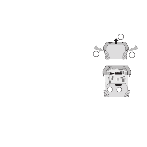
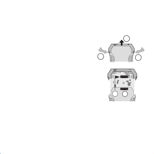
3.2 Opening the unit
Disconnect the plugs. Disengage the top part of
the housing by carefully pressing the latches on
both sides (1). Pull out the top part of the housing and the electronics section until they lock
(2).
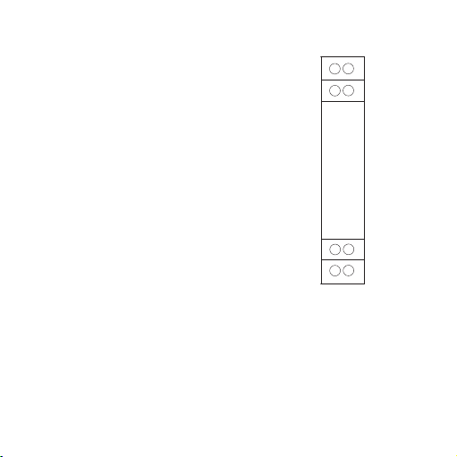
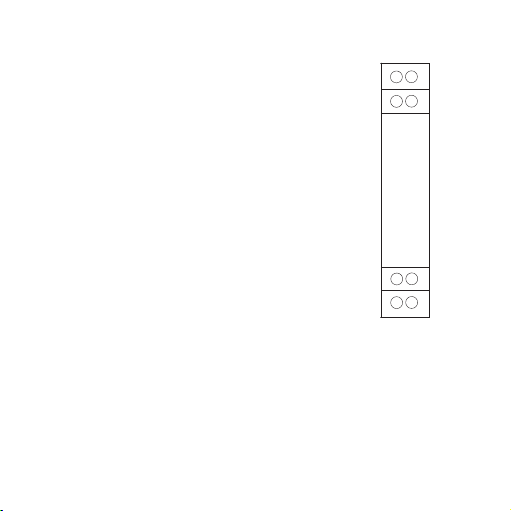
3.3 Settings
Set input and output ranges, minimum input values
and measuring span via the DIP switches SW1 and
SW2.
Set the input range via the DIP switches
(no frequency generator required):
2 cases are to be distinguished:
1. below measurement frequency = 0 Hz
– Select operating mode "0...fmax". S2.3 = 0 and S2.4 = 0
– Set upper measurement frequency via the DIP switches
S1 and S2.1, S2.2 (see table).
– Ready!
2. Lower measurement frequency ≠ 0 Hz
– First, the lower measurement frequency has to be saved.
Select operating mode "save from fmin". S2.3 = 1 and S2.4 = 0
1
1
2
SW2
SW1
Page 5

3
Set upper measurement frequency via the DIP switches S1 and S2.1, S2.2
(see table).
Connect the module to the power supply to save the frequency.
– Select operating mode "fmin...fmax". S2.3 = 0 and S2.4 = 1
– Set upper measurement frequency via the DIP switches S1
and S2.1, S2.2 (see table).
– Ready!
Setting the input range using a frequency generator:
– Select the switch setting for saving the min. frequency
S2.1=0; S2.2=1; S2.3=1 and S2.4=1
– Apply min. frequency to the module
– Connect the module to the power supply.
– The LED lights up when the input frequency is measured.
The frequency has been saved when the LED goes out;
the module can be disconnected from the power supply.
– Repeat the process with the max. frequency: S2.1=1;
S2.2=0; S2.3=1 and S2.4=1.
– Select special range: S2.1=1; S2.2=1; S2.3=1 and S2.4=1
– Ready!
Page 6
4
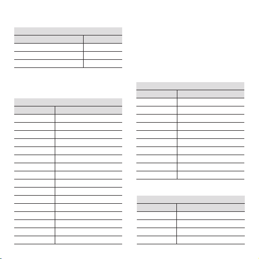
Selecting the frequency
Switch 2
C12
X1 0 0
X10 0 1
X100 1 0
X1000 1 1
Selecting the frequency
Switch 1
B 5 678
0.0 0 0 0 0
0.1 0 0 0 1
0.2 0 0 1 0
0.3 0 0 1 1
0.4 0 1 0 0
0.5 0 1 0 1
0.6 0 1 1 0
0.7 0 1 1 1
0.8 1 0 0 0
0.9 1 0 0 1
Selecting the frequency
Switch 1
A 1234
0 0000
1 0001
2 0010
3 0011
4 0100
5 0101
6 0110
7 0111
8 1000
9 1001
10 1010
11 1011
12 1100
13 1101
14 1110
15 1111
Selecting the operating mode
Switch 2
Operating mode 3 4
0...fmax 0 0
fmin...fmax 0 1
save from fmin 1 0
f=(A+B)xC
Page 7
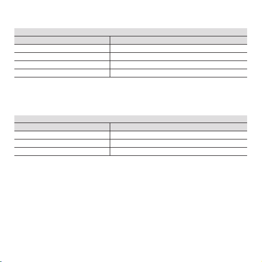
55
Special range (frequency generator is required)
Switch 2
123 4
Save min. frequency 0 1 1 1
Save max. frequency 1 0 1 1
Select special range 1 1 1 1
Selecting the output
Switch 2
Output 5 6 7 8
0...10 V 1 0 1 1
0...20 mA 0 0 0 0
4...20 mA 0 1 0 0
0...5 V 1 1 1 1
Page 8

66
Selecting the frequency
Switch 1
B 5 678
0.5 0 101
Selecting the frequency
Switch 2
C12
x1000 1 1
Selecting the output
Switch 2
Output 5 6 7 8
0...10 V 1 0 1 1
ready
Selecting the frequency
Switch 1
A 1234
10 1010
Selecting the operating mode
Switch 2
Operating mode
34
0...fmax 0 0
3.4 Example 1
Input frequency: 0...10.5 kHz
Output: 0...10 V
Set max. frequency
Page 9

77
Selecting the output
Switch 2
Output 5 6 7 8
0...20 mA 0 0 0 0
ready
Selecting the frequency
Switch 2
C12
x100 1 0
Selecting the frequency
Switch 1
B 5 678
0.1 0 001
Selecting the frequency
Switch 1
A1234
81000
Selecting the operating mode
Switch 2
Operating mode
34
fmin...fmax 0 1
Selecting the frequency
Switch 2
C12
x1 0 0
Selecting the frequency
Switch 1
B 5 678
0.6 0 110
Selecting the frequency
Switch 1
A 1234
3 0011
Selecting the operating mode
Switch 2
Operating mode
34
save from fmin
10
Set max. frequency
3.5 Example 2
Input frequency: 3,6...810 Hz
Output: 0...20 mA
Set min. frequency
The module must be briefly connected to the power supply (5s) in
order to save the min. frequency.
Page 10

88
Special range
(frequency generator is required)
Switch 2
Operating mode 1234
Special range 1111
Special range
(frequency generator is required)
Switch 2
Operating mode 1234
Save min.
frequency 0111
3.6 Example 3
Input frequency: 20 kHz...50 kHz
Output: 4...20mA
Special range min. frequency
Special range
(frequency generator is required)
Switch 2
Operating mode 1234
Save max.
frequency 1011
Special range max. frequency
Selecting the special range
Selecting the output
Switch 2
Output 5678
4…20 mA 0100
ready
• Apply min. frequency to the module.
• Connect the module to the power
supply.
• The LED lights up when the min.
input frequency is measured. The
frequency has been saved when the
LED blinks; the module can be
disconnected from the power
supply.
•
Apply max. frequency to the module.
• Connect the module to the power
supply.
• The LED lights up when the max.
input frequency is measured. The
frequency has been saved when the
LED blinks; the module can be
disconnected from the power
supply.
Page 11
99
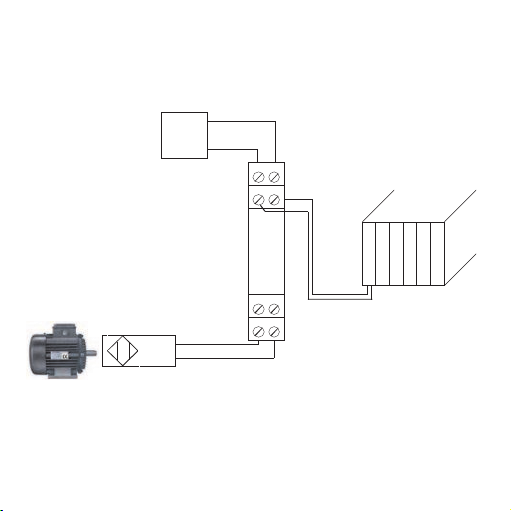
3.7 Application
Namur
activated:
not activated:
Power
N-
N+
<= 1,2mA
>= 2,1 mA
78
56
12
34
Registering motor
revolutions using Namur
sensor
PLC
0…20 mA
Page 12

1010
4. Mounting
The signal conditioners are mounted on standard TS 35 rails.
5. Electrical connection
5.1 Technical Data
Supply voltage 18 ... 30 Vdc/approx. 1 W
Operating temperature 0 °C ... +55 °C
Voltage supply via plug-in jumper. Operating carrying capacity of
cross-connection ^ 2 A
Terminal assignments
1 +15 V power supply for sensor
2 Input PNP
3 Input NPN / Namur
4 Input GND
5 Output (0...10 V; 0/4...20 mA)
6 Output GND
7 Supply voltage + 24 Vdc (cross-connected)
8 Power supply GND (cross-connected)
Wire cross-section max. 2.5 mm
2
Multi-wire conncection max. 1 mm
2
(two wires with same cross-section)
7
8
5
6
2
1
4
3
Page 13

1111
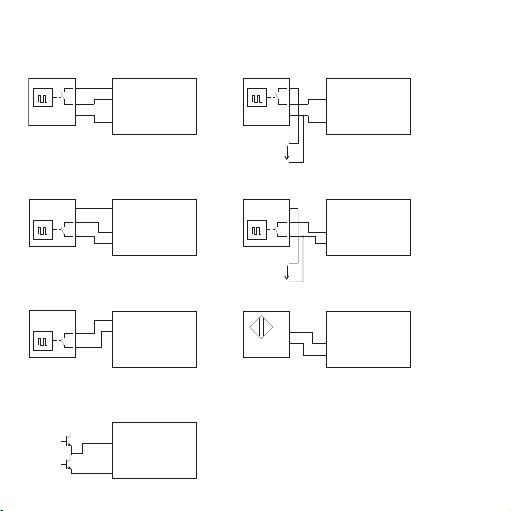
Push-pull output stage
5.2 Wiring diagram
3-wire initiator with PNP output
2-wire inititiator
(residual current <1 mA)
N+
N-
Namur initiator
U= 24 V
U= 24 V
U= 24 V
3-wire initiator with NPN output
3-wire initiator with PNP output
and external power supply
(1) +15V
(2) PNP
(3) NPN / Namur
(4) GND
(1) +15V
(2) PNP
(3) NPN / Namur
(4) GND
3-wire initiator with NPN output
and external power supply
(1) +15V
(2) PNP
(3) NPN / Namur
(4) GND
(1) +15V
(2) PNP
(3) NPN / Namur
(4) GND
(1) +15V
(2) PNP
(3) NPN / Namur
(4) GND
(1) +15V
(2) PNP
(3) NPN / Namur
(4) GND
(1) +15V
(2) PNP
(3) NPN / Namur
(4) GND
Page 14

1212
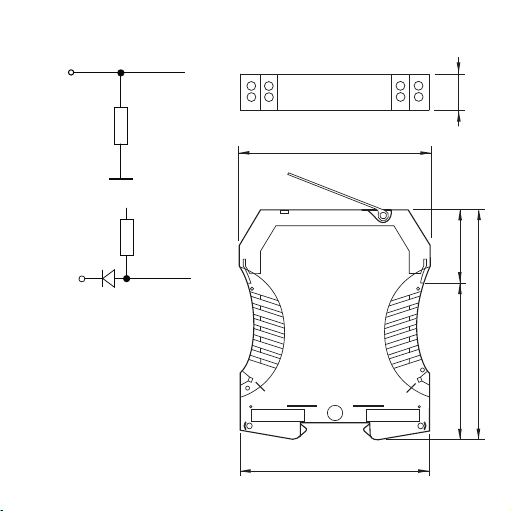
)
P2PN
+8,9
N
V
1kΩ
(
(3) NPN
5.3 Input circuitry 6. Dimensions in mm
3
1
4
2
7
5
8
6
12.5
5,4 kΩ
92.4
111.4
73.4 38
Cross-connections
for
multiple devices
GND
24 Vdc
90
Page 15

1313
7. Accessories
Designation Cat. No.
Plug-In Jumper, 2-pole, black 1492-CJLJ5-2-BL
Plug-In Jumper, 2-pole, red 1492-CJLJ5-2-R
Plug-In Jumper, 2-pole, blue 1492-CJLJ5-2-B
Plug-In Jumper, 2-pole, yellow 1492-CJLJ5-2
Marker Cat. No.
1492-M5X10
Power Supply
24 V DC Output
15 W 1606-XLP15E
30 W 1606-XLP30E
50 W 1606-XLP50E
100 W 1606-XLP100E
120 W (5 A) 1606-XLE120E
Page 16

1414
8. UL Class 1, Division 2 Markings
for selected Signal Conditioners
A. “This equipment is suitable for use in Class I, Division 2, Groups A, B,
C and D hazardous locations or non hazardous locations only or the
equivalent.”
B. “WARNING: EXPLOSION HAZARD - Substitution of components may
impair suitability for use in Class I, Division 2 environments.”
C. “WARNING: EXPLOSION HAZARD - The area must be known to be
non hazardous before servicing/replacing the unit and before installing
or removing I/O wiring.”
D. “WARNING: EXPLOSION HAZARD - Do Not disconnect equipment
unless power has been disconnected and the area is known to be non
hazardous.”
The warning references on this side have only validity for modules with a
UL Class I, Devision 2 permission.
DIR 10000043403
(Version 00)
WARNINGWARNING
Page 17

15
1. Allgemeine Hinweise
Die Analogsignaltrenner der Reihe 931S-F1C2D-DC dürfen nur von
qualifizier tem Fachpersonal installiert werden. Erst nach der fachgerechten
Installation darf das Gerät mit Hilfsenergie versorgt werden. Während des
Betriebs darf keine Bereichsumschaltung vorgenommen werden, da hierbei
berührungsgefähr liche Teile offen liegen. Die nationalen Vorschriften (z. B.
für Deutschland DIN VDE 0100) bei der Installation und Auswahl der Zuleitungen müssen beachtet werden.
Bei Anwendungen mit hohen Isolationsspannungen ist auf genügend
Abstand bzw. Isolation zu Nebengeräten und auf Berührungsschutz zu
achten!
Bei Montage und Einstellarbeiten am 931S-F1C2D-DC ist auf
Schutzmaßnahmen gegen elektrostatische Entladung (ESD) zu
achten.
2. Anwendung
Der Analogsignaltrenner 931S-F1C2D-DC dient zur galvani schen
Trennung und Umwandlung von Frequenzsignalen. Ein- und Aus gangssignal sind über DIP-Schalter kalibriert umschaltbar. Ein Nach justieren der voreinstellbaren Messbereiche ist nicht erforderlich.
Das Ausgangssignal ist linear zur Frequenz.
ACHTUNGACHTUNGACHTUNGACHTUNG
Page 18
16
3. Konfigurierung des Gerätes
3.1 Hilfsmittel
Zum Einstellen des Gerätes und zum Anschluss der Leitungen an die
Klemmen wird ein Schraubendreher mit einer Klingenbreite von 2,5 mm
benötigt.
3.2 Gerät öffnen
Stecker abziehen. Durch leichten Druck den
Verschluss auf beiden Seiten des Gehäuses
entriegeln (1), Gehäuseoberteil und Elektronik
herausziehen (2).
3.3 Einstellungen
Einstellung von Ein- und Ausgangsbereich,
minimalen Eingangsgröße und Messspanne mittels
der DIP-Schalter SW1 und SW2.
Einstellen des Eingangsbereiches über die DIPSchalter (kein Frequenzgenerator erforderlich):
Es sind 2 Fälle zu unterscheiden:
1. untere Messfrequenz = 0 Hz
– Betriebsart "0...fmax" auswählen. S2.3 = 0 und S2.4 = 0
– obere Messfrequenz über die DIP-Schalter S1 und S2.1, S2.2
einstellen (siehe Tabelle)
– Fertig
2. untere Messfrequenz ≠ 0 Hz
– zunächst muss die untere Messfrequenz gespeichert werden.
Betriebsart "speichern von fmin" auswählen. S2.3 = 1 und S2.4 = 0
1
1
2
SW2
SW1
Page 19

17
Frequenz über die DIP-Schalter S1 und S2.1, S2.2 einstellen (siehe Tabelle)
Zum Speichern der Frequenz den Baustein kurz an die Spannungsversorgung anschließen
– Betriebsart "fmin...fmax" auswählen. S2.3 = 0 und S2.4 = 1
– obere Messfrequenz über die DIP-Schalter S1 und S2.1, S2.2
einstellen (siehe Tabelle)
– Fertig
Einstellen des Eingangsbereiches mit einem Frequenzgenerator:
– Die Schalterstellung für die Speicherung der min. Frequenz wählen:
S2.1=0; S2.2=1; S2.3=1 und S2.4=1
– Min. Frequenz am Baustein anlegen
– Baustein an die Spannungsvorsorgung anschließen
– Die LED leuchtet auf, wenn die Eingangsfrequenz gemessen wird.
Wenn die LED erlischt ist die Frequenz gespeichert worden und der
Baustein kann wieder von der Spannungsversorgung getrennt werden.
– Vorgang mit der max. Frequenz wiederholen: S2.1=1; S2.2=0; S2.3=1
und S2.4=1
– Sonderbereich auswählen: S2.1=1; S2.2=1; S2.3=1 und S2.4=1
– Fertig
Page 20

18
Auswahl der Frequenz
Schalter 2
C12
X1 0 0
X10 0 1
X100 1 0
X1000 1 1
Auswahl der Frequenz
Schalter 1
B 5 678
0,0 0 0 0 0
0,1 0 0 0 1
0,2 0 0 1 0
0,3 0 0 1 1
0,4 0 1 0 0
0,5 0 1 0 1
0,6 0 1 1 0
0,7 0 1 1 1
0,8 1 0 0 0
0,9 1 0 0 1
Auswahl der Frequenz
Schalter 1
A 1234
0 0000
1 0001
2 0010
3 0011
4 0100
5 0101
6 0110
7 0111
8 1000
9 1001
10 1010
11 1011
12 1100
13 1101
14 1110
15 1111
Auswahl der Betriebsart
Schalter 2
Betriebsart 3 4
0...fmax 0 0
fmin...fmax 0 1
speichern von fmin 1 0
f=(A+B)xC
Page 21

19
Sonderbereich (Frequenzgenerator erforderlich)
Schalter 2
123 4
min. Frequenz speichern 0 1 1 1
max.Frequenz speichern 1 0 1 1
Sonderbereich auswählen 1 1 1 1
Auswahl des Ausgangs
Schalter 2
Ausgang 5 6 7 8
0...10 V 1 0 1 1
0...20 mA 0 0 0 0
4...20 mA 0 1 0 0
0...5 V 1 1 1 1
Page 22

20
Auswahl der Frequenz
Schalter 1
B 5 678
0,5 0 101
Auswahl der Frequenz
Schalter 2
C12
x1000 1 1
Auswahl des Ausgangs
Schalter 2
Ausgang 5 6 7 8
0...10 V 1 0 1 1
Fertig
Auswahl der Frequenz
Schalter 1
A 1234
10 1010
Auswahl der Betriebsart
Schalter 2
Betriebsart 3 4
0...fmax 0 0
3.4 Beispiel 1
Eingangsfrequenz: 0...10,5 kHz
Ausgang: 0...10 V
Max. Frequenz einstellen
Page 23

21
Auswahl des Ausgangs
Schalter 2
Ausgang 5 6 7 8
0...20 mA 0 0 0 0
Fertig
Auswahl der Frequenz
Schalter 2
C12
x100 1 0
Auswahl der Frequenz
Schalter 1
B 5 678
0,1 0 001
Auswahl der Frequenz
Schalter 1
A1234
81000
Auswahl der Betriebsart
Schalter 2
Betriebsart 3 4
fmin...fmax 0 1
Auswahl der Frequenz
Schalter 2
C12
x1 0 0
Auswahl der Frequenz
Schalter 1
B 5 678
0,6 0 110
Auswahl der Frequenz
Schalter 1
A 1234
3 0011
Auswahl der Betriebsart
Schalter 2
Betriebsart 3 4
speichern von fmin
10
Max. Frequenz einstellen
3.5 Beispiel 2
Eingangsfrequenz: 3,6...810 Hz
Ausgang: 0...20 mA
Min. Frequenz einstellen
Zur Speicherung der min. Frequenz
muss das Modul kurz an die
Betriebsspannung angeschlossen
werden (5s.)
Page 24

22
Sonderbereich
(Frequenzgenerator erforderlich)
Schalter 2
Betriebsart 1234
Sonderbereich 1111
Sonderbereich
(Frequenzgenerator erforderlich)
Schalter 2
Betriebsart 1234
min. Frequenz
speichern 0111
3.6 Beispiel 3
Eingangsfrequenz: 20 kHz...50 kHz
Ausgang: 4...20mA
Sonderbereich min. Frequenz
Sonderbereich
(Frequenzgenerator erforderlich)
Schalter 2
Betriebsart 1234
max. Frequenz
speichern 1011
Sonderbereich max. Frequenz
Auswahl des Sonderbereichs
Auswahl des Ausgangs
Schalter 2
Ausgang 5678
4…20 mA 0100
Fertig
• Min. Frequenz am Baustein anlegen
• Baustein an die Spannungsversorgung anschließen.
• Die LED leuchtet auf, wenn die min.
Eingangsfrequenz gemessen wird.
Wenn die LED blink ist die Frequenz
gespeichert worden und der Baustein kann wieder von der Spannungsversorgung getrennt werden.
•
Max. Frequenz am Baustein anlegen
• Baustein an die Spannungsversorgung anschließen.
• Die LED leuchtet auf, wenn die max.
Eingangsfrequenz gemessen wird.
Wenn die LED blink ist die Frequenz
gespeichert worden und der Baustein kann wieder von der Spannungsversorgung getrennt werden.
Page 25

23
3.7 Applikation
Namur
betätigt:
unbetätigt:
Power
<= 1,2mA
>= 2,1 mA
Motordrehzahlerfassung
mit Namurs ens or
78
56
SPS
0…20 mA
12
N-
N+
34
Page 26
24
4. Montage
Die Analogsignaltrenner werden auf TS 35 Normschienen aufgerastet.
5. Der elektrische Anschluss
5.1 Technische Daten
Versorgungsspannung 18 ... 30 Vdc/ca. 1 W
Betriebstemperatur 0 °C ... +55 °C
Spannungsversorgung ausgeführt über Querverbindungen
Stromtragfähigkeit der Querverbindung ≤ 2 A
Klemmenbelegung
1 +15 V Versorgung für Sensor
2 PNP- Eingang
3 NPN- Eingang / Namur
4 GND- Eingang
5 Ausgang (0...10 V; 0/4...20 mA)
6 Ausgang GND
7 Versorgung + 24 Vdc (querverbunden)
8 Versorgung GND (querverbunden)
Anschlussquerschnitt max. 2,5 mm
2
Mehrleiteranschluss max. 1 mm
2
(zwei Leiter gleichen Querschnitts)
7
8
5
6
2
1
4
3
Page 27

25
Gegentaktausgangsstufe
5.2 Anschlussbelegung der Sensoren
3- Draht Initiator mit PNP-Ausgang
2- Draht Initiator
(Reststrom <1 mA)
N+
N-
Namur Initiator
U= 24 V
U= 24 V
U= 24 V
3- Draht Initiator mit NPN-Ausgang
3- Draht Initiator mit PNP-Ausgang
und externer Versorgung
(1) +15V
(2) PNP
(3) NPN / Namur
(4) GND
(1) +15V
(2) PNP
(3) NPN / Namur
(4) GND
3- Draht Initiator mit NPN-Ausgang
und externer Versorgung
(1) +15V
(2) PNP
(3) NPN / Namur
(4) GND
(1) +15V
(2) PNP
(3) NPN / Namur
(4) GND
(1) +15V
(2) PNP
(3) NPN / Namur
(4) GND
(1) +15V
(2) PNP
(3) NPN / Namur
(4) GND
(1) +15V
(2) PNP
(3) NPN / Namur
(4) GND
Page 28

26
)
P2PN
+8,9
N
V
1kΩ
(
(3) NPN
5.3 Eingangsbeschaltung 6. Abmessungen in mm
92,4
90
111,4
73,4 38
Querverbindungen
für
Spannungsversorgung
GND
24 Vdc
12,5
6
7
1
2
8
3
4
5
5,4 kΩ
Page 29

27
7. Zubehör
Bezeichnung Best.-Nr.
Querverbindung – 2,5 N/2 schwarz 1492-CJLJ5-2-BL
Querverbindung – 2,5 N/2 rot 1492-CJLJ5-2-R
Querverbindung – 2,5 N/2 blau 1492-CJLJ5-2-B
Querverbindung – 2,5 N/2 gelb 1492-CJLJ5-2
Marker Best.-Nr.
1492-M5X10
Power Supply
24 V DC Output
15 W 1606-XLP15E
30 W 1606-XLP30E
50 W 1606-XLP50E
100 W 1606-XLP100E
120 W (5 A) 1606-XLE120E
DIR 10000043403
(Version 00)
Page 30

28
1. Indications générales
Les séparateurs de la série 931S-F1C2D-DC ne doivent être installés que
par du personnel qualifié. L'alimentation électrique de l'appareil ne doit être
réalisée qu'après une installation con forme aux prescrip tions. Ne pas changer de plage pendant le fonctionnement, au risque de dé couvrir des pièces
au contact dangereux. Un réglage fin avec les potentiomètres situés en face
avant doit être effectué unique ment avec un tournevis correcte ment isolé
contre la tension appliquée en entrée ! Les directives nationales en vigeur
doivent être prises en compte pour l’installation et la sélection des câbles.
En cas d'utilisation avec des tensions d’isolement élevées, veiller à avoir
une distance ou une isolation suffisante par rapport aux appareils voisins et
respecter la protection contre les contacts!
Lors du montage et des opérations de réglage du séparateur de
signaux analogiques, observer les mesures de protection contre
les décharges électrostatiques.
2. Utilisation
Le séparateur analogique de signal 931S-F1C2D-DC sert à la séparation
galvanique et à la conversion des signaux de fréquence. La commutation
du signal d'entrée et de sortie calibrés s'effectue par boîtier DIP. Il n'est
pas nécessaire d'ajuster ultérieurement les plages de mesure préréglées.
Le signal de sortie est linéaire par rapport à la fréquence.
2828
ATTENTIONATTENTION
Page 31

2929
3. Configuration
3.1 Accessoires
Pour raccorder les conducteurs aux bornes il faut avoir un tournevis avec
une étendue de 2,5 mm.
3.2 Ouverture de l’appareil
Retirer les fiches. Presser légèrement sur les
deux languettes (1) pour déverrouiller la partie
supérieure du boîtier. On peut ainsi sortir la
partie supé rieure et l’électronique jusqu’à ce
qu’elles s’enclenchent (2).
3.3 Réglages
Les réglages des plages d'entrée et de sortie, des
grandeurs d'entrée minimales et d'étendue de mesure s'effectuent au moyen des boîtiers DIP SW1 et
SW2.
Le réglage de la plage d'entrée s'effectue par
commutateur DIP (pas de générateur de
fréquence nécessaire): Il faut distinguer 2 cas :
1. Fréquence inférieure de mesure = 0 Hz
– sélectionner mode "0…fmax". S2.3 = 0 et S2.4 = 0
– régler la fréquence supérieure de mesure par les commutateurs
DIP S1 et S2.1, S2.2 (cf. tableau)
– C'est tout
2. il faut d'abord mémoriser la fréquence de mesure inférieure.
Sélectionner mode "mémorisation de fmin". S2.3 = 1 et S2.4 = 0
1
1
2
SW2
SW1
29
Page 32

3030
Régler la fréquence par les commutateurs DIP S1 et S2.1, S2.2
(cf. tableau)
Pour mémoriser la fréquence du module, brancher un bref instant la tension d'alimentation
– sélectionner mode "fmin…fmax". S2.3 = 1 et S2.4 = 0
– régler la fréquence supérieure de mesure par les commutateurs
DIP S1 et S2.1, S2.2 (cf. tableau)
– C'est tout
Réglage de la plage d'entrée à l'aide d'un générateur de fréquence:
– Sélectionner la position du commutateur pour mémoriser la
fréquence min.: S2.1=0; S2.2=1; S2.3=1 et S2.4=1
– Appliquer la fréquence min sur le module
– Raccorder le module à la tension d'alimentation
– La DEL s'allume lors de la mesure de la fréquence d'entrée.
Lorsque la DEL s'éteint, la fréquence est mémorisée et le module
peut de nouveau être débranché de l'alimentation.
– Répéter la procédure pour la fréquence max.: S2.1=1; S2.2=0;
S2.3=1et S2.4=1
– Sélection d'une plage spéciale : S2.1=1; S2.2=1; S2.3=1 et S2.4=1
– C'est tout
30
Page 33

3131
Sélection de la fréquence
Commutateur
2
C12
X1 0 0
X10 0 1
X100 1 0
X1000 1 1
Sélection de la fréquence
Commutateur
1
B 5 678
0.0 0 000
0.1 0 001
0.2 0 010
0.3 0 011
0.4 0 100
0.5 0 101
0.6 0 110
0.7 0 111
0.8 1 000
0.9 1 001
Sélection de la fréquence
Commutateur
1
A 1234
0 0000
1 0001
2 0010
3 0011
4 0100
5 0101
6 0110
7 0111
8 1000
9 1001
10 1010
11 1011
12 1100
13 1101
14 1110
15 1111
Sélection du mode de fonctionnement
Commutateur
2
Mode de fonctionnement
34
0...fmax 0 0
fmin...fmax 0 1
mémorisation de fmin 1 0
f=(A+B)xC
31
Page 34

32
Plage spéciale (générateur de fréquence nécessaire)
Commutateur 2
123 4
mémoriser la fréquence min 0 1 1 1
mémoriser la fréquence max. 1 0 1 1
sélectionner une plage spéciale
111 1
Sélection de la sortie
Commutateur 2
Sortie 5 6 7 8
0...10 V 1 0 1 1
0...20 mA 0 0 0 0
4...20 mA 0 1 0 0
0...5 V 1 1 1 1
32
Page 35

33
Sélection de la fréquence
Commutateur
1
B 5 678
0.5 0 101
Sélection de la fréquence
Commutateur
2
C12
x1000 1 1
Sélection de la sortie
Commutateur
2
Sortie 5 6 7 8
0...10 V 1 0 1 1
C'est tout
Sélection de la fréquence
Commutateur
1
A1234
10 1010
Sélection du mode de fonctionnement
Commutateur
2
Mode de fonctionnement
34
0...fmax 0 0
3.4 Exemple 1
Fréquence d'entrée: 0...10,5 kHz
Sortie: 0...10 V
Régler la fréquence max.
33
Page 36

34
Sélection de la sortie
Commutateur
2
Sortie 5678
0...20 mA 0 0 0 0
C'est tout
Sélection de la fréquence
Commutateur
2
C12
x100 1 0
Sélection de la fréquence
Commutateur 1
B 5 678
0,1 0 001
Sélection de la fréquence
Commutateur
1
A1234
81000
Sélection du mode de fonctionnement
Commutateur 2
Mode de fonctionnement
34
fmin...fmax 0 1
Sélection de la fréquence
Commutateur
2
C12
x1 0 0
Sélection de la fréquence
Commutateur
1
B 5 678
0,6 0 110
Sélection de la fréquence
Commutateur
1
A 1234
3 0011
Sélection du mode de fonctionnement
Commutateur
2
Mode de fonctionnement
34
mémorisation de fmin
10
Régler la fréquence max.
3.5 Exemple 2
Fréquence d'entrée: 3,6...810 Hz
Sortie: 0...20 mA
Régler la fréquence min.
Pour mémoriser la fréquence min.,
il faut que le module soit raccordé
à la tension de service (5 s).
34
Page 37

35
Plage spéciale (générateur
de fréquence nécessaire)
Commutateur
2
Mode de fonctionnement
1234
plage spéciale 1111
Plage spéciale (générateur
de fréquence nécessaire)
Commutateur
2
Mode de fonctionnement
1234
mémoriser la
fréquence min 0111
3.6 Exemple 3
Fréquence d'entrée: 20 kHz...50 kHz
Sortie: 4...20mA
Plage spéciale fréquence min.
Plage spéciale (générateur
de fréquence nécessaire)
Commutateur
2
Mode de fonctionnement
1234
mémoriser la
fréquence max. 1011
Plage spéciale fréquence max.
Sélection de la plage spéciale
Sélection de la sortie
Commutateur
2
Sortie 5678
4…20 mA 0100
C'est tout
•
Appliquer la fréquence min. sur le module.
• Raccorder le module à la tension
d'alimentation.
• La DEL s'allume lors de la mesure
de la fréquence min. d'entrée.
Lorsque la DEL clignote, la
fréquence est mémorisée et le
module peut de nouveau être
débranché de l'alimentation.
•
Appliquer la fréquence max. sur le
module.
• Raccorder le module à la tension
d'alimentation.
• La DEL s'allume lors de la mesure
de la fréquence max. d'entrée.
Lorsque la DEL clignote, la
fréquence est mémorisée et le
module peut de nouveau être
débranché de l'alimentation.
35
Page 38

36
3.7 Application
36
Power
78
56
de rotation du moteur
par capteur Namur
API
0…20 mA
12
Acquisition de la vitesse
N-
<= 1,2mA
>= 2,1 mA
N+
Namur
Activé:
Non activé:
34
Page 39
3737
4. Montage
Les séparateurs sont encliquetés sur des rails de norme TS 35.
5. Le raccordement électrique
5.1 Caractéristiques techniques
Tension d’alimentation 18 ... 30 Vdc/env. 1 W
Température de service 0 °C ... +55 °C
Alimentation en tension sortie sur connexions transversales
(max. 2 A)
Brochage
1 Alimentation +15 V pour le capteur
2 Entrée PNP
3 Entrée NPN / Namur
4 Entrée GND
5 Sortie (0...10 V; 0/4...20 mA)
6 Sortie GND
7 Alimentation + 24 Vdc (connexion transversale)
8 Alimentation GND (connexion transversale)
Section raccordement maxi. 2,5 mm
2
Raccordement multibrins maxi. 1 mm
2
(deux fils de même section)
37
7
8
5
6
2
1
4
3
Page 40
38
Etage de sortie symétrique
5.2 Brochage
Commutateur capacitif 3
fils à sortie PNP
Commutateur capacitif 2 fils
(courant résiduel < 1 mA)
N+
N-
Commutateur capacitif Namur
U= 24 V
U= 24 V
U= 24 V
Commutateur capacitif 3
fils à sortie NPN
Commutateur capacitif 3 fils à sortie
PNP et alimentation externe
(1) +15V
(2) PNP
(3) NPN / Namur
(4) GND
(1) +15V
(2) PNP
(3) NPN / Namur
(4) GND
Commutateur capacitif 3 fils à sortie
NPN et alimentation externe
(1) +15V
(2) PNP
(3) NPN / Namur
(4) GND
(1) +15V
(2) PNP
(3) NPN / Namur
(4) GND
(1) +15V
(2) PNP
(3) NPN / Namur
(4) GND
(1) +15V
(2) PNP
(3) NPN / Namur
(4) GND
(1) +15V
(2) PNP
(3) NPN / Namur
(4) GND
38
Page 41
39
)
P2PN
+8,9
N
V
1kΩ
(
(3) NPN
5.3 Raccordement d'entrée 6. Dimensions en mm
39
3
1
4
2
7
5
8
6
12.5
5,4 kΩ
92.4
Connexion
transversale
d’alimentation
en tension
GND
24 Vdc
111.4
73.4 38
90
Page 42

40
7. Accessoires
Désignation Réf.
Connexion transversale – 2,5 N/2 noir 1492-CJLJ5-2-BL
Connexion transversale – 2,5 N/2 rouge 1492-CJLJ5-2-R
Connexion transversale – 2,5 N/2 bleu 1492-CJLJ5-2-B
Connexion transversale – 2,5 N/2 jaune 1492-CJLJ5-2
Marker Réf.
1492-M5X10
Power Supply
24 V DC Output
15 W 1606-XLP15E
30 W 1606-XLP30E
50 W 1606-XLP50E
100 W 1606-XLP100E
120 W (5 A) 1606-XLE120E
40
DIR 10000043403
(Version 00)
 Loading...