

Page 1
Installation Instruction
English 2
Deutsch 15
Français 28
Active Converter, 3 Way
931S-C4C5D-BC
DIR 10000043400
(Version 00)
10000043400
Page 2

1. General instructions
• Disconnect power prior to installation
• Installation only by Qualified personnel
• Follow all applicable local and national electrical codes
• Due to potential hazardous voltages in close proximity, use a nonconductive tool and proper PPE when adjusting the potentiometers
on the front panel.
For applications with high isolation voltages, take measures to prevent
accidental contact and make sure that there is sufficient distance or
insulation between adjacent devices!
Appropriate safety measures against electrostatic discharge
(ESD) should be taken during assembly and adjustment work
on the 931S-C4C5D-BC.
2. Application
The 3 Way Active Converters 931S-C4C5D-BC are used for galvanic
isolation and conversion of signals in the range from ±20 mV to ±200 V and
±0.1 mA to ±100 mA. Depending on the model, input and output signals
are permanently set or you can select calibrated ranges by means of
DIP switches. The preset measuring ranges do not have to be fine adjusted.
Other transmission ranges are infinitely adjustable within the ranges
mentioned above using potentio meters. Signal transmission is linear.
By means of the broad-range mains adapter, the units can be powered by
voltages from 22 to 230 V AC/DC.
2
WARNINGWARNING
Page 3
3
3. Configuration
3.1 Equipment
A screwdriver with a width of 2.5 mm is required to adjust the unit and to
connect the wires to the terminals.
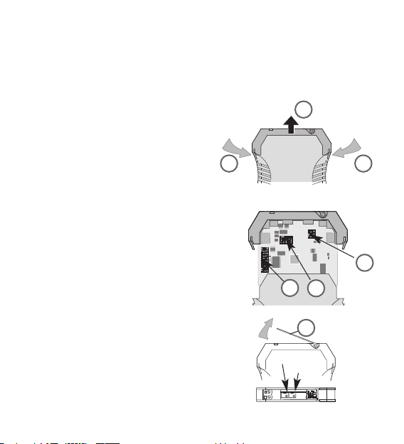
3.2 Opening the unit
Disconnect the plugs. Disengage the top
part of the housing by carefully pressing the
latches on both sides (1). Pull out the top
part of the housing and the electronics
section until they unlock (2).
3.3 Settings
Set the input and output ranges, offset and
bandwidth using DIP switches S1, S2 and S3 as
indicated in the following tables. When selecting
a variable amplification or offset setting, an
additional adjustment can be made using the
Span (amplification) or Zero (offset) potentio meters located under the top cover (3).
1
2
1
3
Span
Zero
S1
S2
S3
Page 4
4
Page 5
Selected range can be documented on enclosure side.
Factory setting: 0 to ±10 V / 0 to ± 10 V, 0 % offset, bandwidth 10 Hz
Switch
Outpu
1S3
Output range OS EV 56712
0 to ±10 V 10 V 10 V
ON ON
2 to 10 V 8 V 10 V
ON ON ON
0 to ±5 V 5 V 5 V
ON ON ON
1 to 5 V 4 V 5 V
ON ON ON ON
0 to ±20 mA 20 mA 20 mA
ON
4 to 20 mA 16 mA 20 mA
ON ON
Offset
(in % of output span)
S1 S2
8 9 10 5
0 %
ON
-100 %
ON ON
-50 %
ON ON
+50 %
ON ON ON
+100 %
ON ON
Zero potentiometer: additional ±25 %
Switch S3 3
Bandwidth 10 kHz
Bandwidth 10 Hz
ON
5
Page 6

3.5 Setting examples
1.
.
Input –150 mV to +150 mV, output –20 mA to +20 mA
2.
.
Input +10 mV to +165 mV, output 0 mA to +20 mA
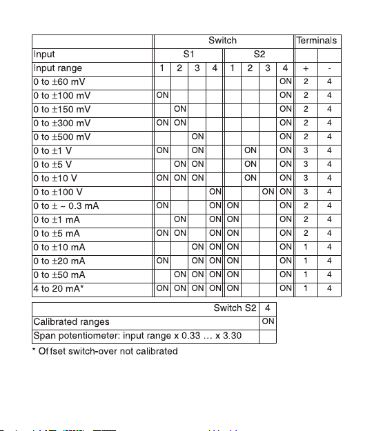
a. Switch on input range 0 to ±150 mV, activate Span potentiometer.
Switch on output range 0 to ±20 mA and offset 0 %
Input S1 S2
Input range 1234123
0 to ±150 mV
ON
Switch S2 4
Span potentiometer: input range x 0.3 to x 3.33
Outpu
1S3
Output range 56712
0 to ±20 mA
ON
Offset
(in % of output span)
S1 S2
8 9 10 5
0 %
ON
Input S1 S2
Input range 12341234
0 to ±150 mV
ON ON
Outpu 1S3
Output range 56712
0 to ±20 mA
ON
Offset
(in % of output span)
S1 S2
8 9 10 5
+ 0 %
ON
6
Page 7

b. Set input to 155 mV, set output to 20 mA with Span potentiometer
c. Activate Zero potentiometer.
Set input to 10 mV, set output to 0 mA with Zero potentiometer
Offset
(in % of output span)
S2
5
Zero potentiometer: additional ± 25 %
7
Page 8
8
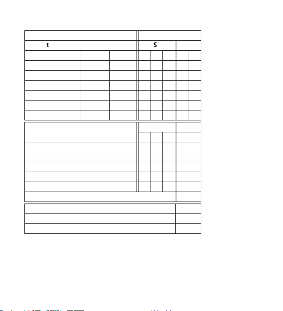
3.6 Setting tool for all input and output values
Definitions: In
min
= smallest input value
In
max
= largest input value
Out
min
= smallest output value
Out
max
= largest output value
OS = output span (take from table on Pg 22)
EV = upper end value (take from table on Pg 22)
1. Select output range of unit (according to table on Pg 22) so that Out
min
and Out
max
are within the output range.
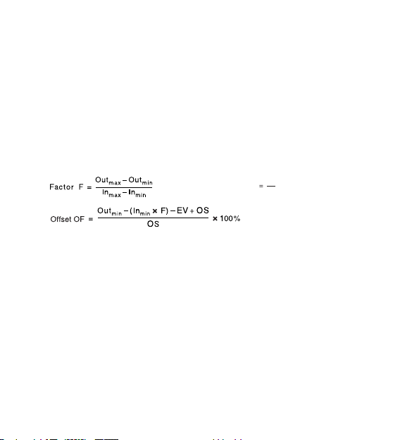
2. Calculate the following auxiliary quantities:
3. Set all DIP switches to OFF.
4. Calculate input range IR, set output range and offset OF with DIP
switches.
4a. If the calculated offset OF does not correspond with an offset which can
be set with the DIP switches, set the closest offset (see table on page 22)
and activate the zero potentiometer (switch 2-5 OFF), short-circuit input
and adjust output to value Out
min
– (In
min
x F).
4b. If the calculated input range IR does not correspond with a range
which can be set with the DIP switches set the largest range within
0.33 x IR … 3.30 x IR (see table on page 21) and activate the span
potentiometer (switch 2-4 OFF), modulate input with value ≠ 0 (see table
on page 21 for terminals) and adjust output to required value (e.g. set
In
max
, adjust to Out
max
).
Input range
IR
OS
F
Page 9
4. Mounting
The signal conditioners are mounted on standard TS 35 rails.
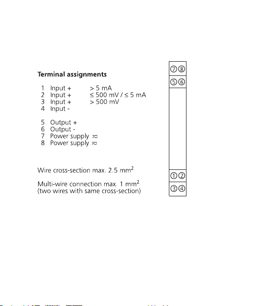
5. Electrical connection
Do not operate inputs for current and voltage simultaneously!
5.1 Power supply
22 to 230 V AC/DC ± 10 %, approx. 1 W, AC 48 to 62 Hz
9
Page 10
10
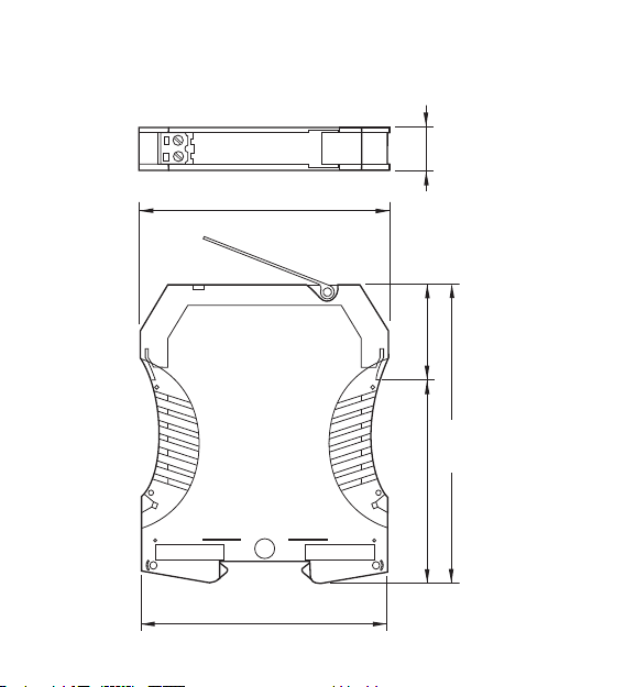
6. Dimensions
92.4
90
38
111.4
73.4
12.5
Page 11
11
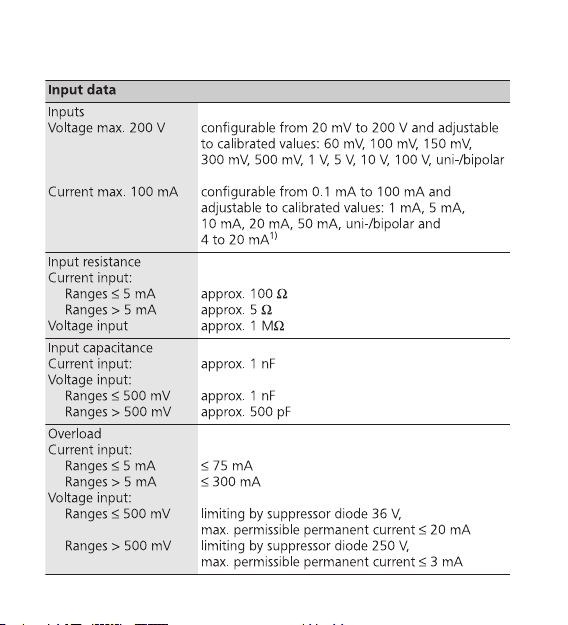
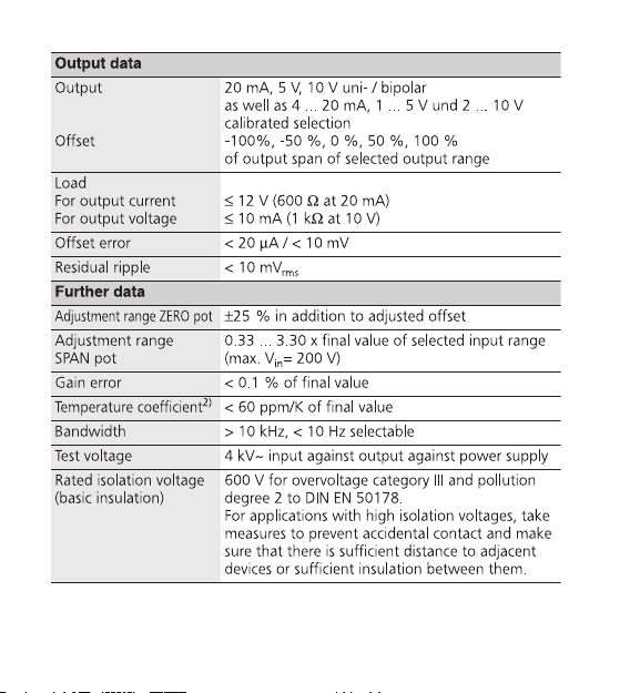
7. Technical Data
Page 12
12
Page 13

13
Page 14

8. Accessories
Marker
1492-M5X10
Power Supply
24 VDC Output
15 W 1606-XLP15E
30 W 1606-XLP30E
50 W 1606-XLP50E
100 W 1606-XLP100E
120 W (5 A) 1606-XLE120E
14
DIR 10000043400
(Version 00)
Page 15

1. Allgemeine Hinweise
Die Analogsignaltrenner der Reihe 931S-C4C5D-BC dürfen nur von qualifizier tem
Fachpersonal installiert werden. Erst nach der fachgerechten Installation darf
das Gerät mit Hilfsenergie versorgt werden. Während des Betriebs darf keine
Bereichsumschaltung vorgenommen werden, da hierbei berührungsgefährliche
Teile offen liegen. Ein Feinabgleich über die frontseitigen Potis darf nur mit einem
Schraubendreher erfolgen, der sicher gegen die an den Eingang gelegte Spannung isoliert ist! Die nationalen Vorschriften (z. B. für Deutschland DIN VDE 0100)
bei der Installation und Auswahl der Zuleitungen müssen beachtet werden.
Eine zweipolige Trennvorrichtung zwischen Gerät und Netz ist vorzusehen.
Bei Anwendungen mit hohen Isolationsspannungen ist auf genügend Abstand
bzw. Isolation zu Nebengeräten und auf Berührungsschutz zu achten!
Bei Montage und Einstellarbeiten am 931S-C4C5D-BC ist auf
Schutzmaßnahmen gegen elektrostatische Entladung (ESD) zu achten.
2. Anwendung
Die Analogsignaltrenner dienen zur galvani schen Trennung und Umwandlung
von Signalen im Bereich von ±20 mV bis ±200 V und ±0,1 mA bis ±100 mA.
Ein- und Ausgangssignal sind je nach Typ fest eingestellt oder über DIPSchalter kalibriert umschaltbar. Ein Nachjustieren der voreinstellbaren
Meßbereiche ist nicht erforderlich. Für andere Übertragungsbereiche ist eine
stufenlose Einstellung innerhalb der oben genannten Bereiche über
Potentiometer möglich. Die Übertragung des Meßsignals ist linear.
Durch das Weitbereichsnetzteil können die Geräte mit Spannungen von
22 ... 230 V AC/DC versorgt werden.
15
ACHTUNGACHTUNG
Page 16

16
3. Konfigurierung des Gerätes
3.1 Hilfsmittel
Zum Einstellen des Gerätes und zum Anschluß der Leitungen an die
Klemmen wird ein Schraubendreher mit einer Klingenbreite von 2,5 mm
benötigt.
3.2 Gerät öffnen
Stecker abziehen. Durch leichten Druck
den Verschluß auf beiden Seiten des
Gehäuses entriegeln (1), Gehäuseoberteil
und Elektronik herausziehen (2).
3.3 Einstellungen
Einstellung von Ein- und Ausgangsbereich,
Offset (Verschiebung) und Bandbreite mittels
der DIP-Schalter S1, S2 und S3 gemäß
nachfolgender Tabellen.
Bei Auswahl einer variablen Einstellung von
Verstärkung oder Offset zusätzliche Einstellung über die frontseitig unterhalb der
Abdeckung (3) zugänglichen Potis Span
(Verstärkung) bzw. Zero (Offset).
.
1
2
1
3
Span
Zero
S1
S2
S3
Page 17

17
Page 18

Eingestellter Bereich kann auf der Gehäuseseite dokumentiert werden.
Liefereinstellung: 0 ... ±10 V / 0 ... ±10 V, 0 % Offset, Bandbreite 10 Hz
Schalter
Ausgang S1 S3
Ausgangsbereich AS EW 56712
0 ... ±10 V 10 V 10 V
ON ON
2 ... 10 V 8 V 10 V
ON ON ON
0 ... ±5 V 5 V 5 V
ON ON ON
1 ... 5 V 4 V 5 V
ON ON ON ON
0 ... ±20 mA 20 mA 20 mA
ON
4 ... 20 mA 16 mA 20 mA
ON ON
Offset
(in % der Ausgangsspanne)
S1 S2
8 9 10 5
0 %
ON
-100 %
ON ON
-50 %
ON ON
+50 %
ON ON ON
+100 %
ON ON
Zero-Poti aktiviert: zusätzlich ±25 %
Schalter S3 3
Bandbreite 10 kHz
Bandbreite 10 Hz
ON
18
Page 19

19
3.5 Einstellbeispiele
1. Eingang -150 mV ... +150 mV, Ausgang -20 mA ... +20 mA
2. Eingang +10 mV ... +165 mV, Ausgang 0 ... 20 mA
a. Eingangsbereich 0 ... ±150 mV einschalten, Span-Poti aktivieren,
Ausgangsbereich 0 ... ±20 mA und Offset 0 % einschalten
Eingan 1S2
Eingangsbereich 12341234
0 ... ±150 mV
ON ON
Ausgan 1S3
Ausgangsbereich 56712
0 ... ±20 mA
ON
Offset
(in % der Ausgangsspanne)
S1 S2
8 9 10 5
+0 %
ON
Eingan 1S2
Eingangsbereich 1234123
0 ... ±150 mV
ON
Schalter S2 4
Span-Poti: Eingangsbereich x 0,3 ... x 3,33
Ausgan
1S3
Ausgangsbereich 56712
0 ... ±20 mA
ON
Offset
(in % der Ausgangsspanne)
S1 S2
8 9 10 5
0 %
ON
Page 20

20
b. Eingang auf 155 mV legen, mit Span-Poti Ausgang auf 20 mA einstellen,
c. Zero-Poti aktivieren,
Eingang auf 10 mV legen, mit Zero-Poti Ausgang auf 0 mA einstellen
Offset
(in % der Ausgangsspanne)
S2
5
Zero-Poti: zusätzlich ±25 %
Page 21

3.6 Einstellhilfe für beliebige Ein- und Ausgangswerte
Definitionen: In
min
= kleinster Eingangswert
In
max
= größter Eingangswert
Aus
min
= kleinster Ausgangswert
Aus
max
= größter Ausgangswert
AS = Ausgangsspanne (aus Tab. S. 6 zu entnehmen)
EW = oberer Endwert (aus Tab. S. 6 zu entnehmen)
1. Ausgangsbereich des Gerätes (gemäß Tabelle S. 6) so auswählen, daß
Aus
min
und Aus
max
innerhalb des Ausgangsbereichs liegen.
2. Folgende Hilfsgrößen berechnen:
3. Alle DIP-Schalter auf OFF setzen
4. Ermittelten Eingangsbereich EB, Ausgangsbereich und Offset OF mit
DIP-Schaltern einstellen.
4a. Wenn der ermittelte Offset OF keinem per DIP-Schalter einstellbaren
Offset entspricht, nächstgelegenen Offset einstellen (s. Tabelle S. 6) dann
Zero-Poti aktivieren (Schalter S 2-5 OFF). Eingang kurzschließen und
Ausgang auf den Wert Aus
min
-(In
min
× F) abgleichen.
4b. Wenn der ermittelte Eingangsbereich EB keinem per DIP-Schalter ein-
stellbaren Bereich entspricht, größtmöglichen Bereich einstellen, der
innerhalb 0,33 x EB ... 3,30 x EB liegt (s. Tabelle S. 5) dann Span-Poti
aktivieren (Schalter S 2-4 OFF), Eingang mit Wert ≠ 0 aussteuern
(Anschlußklemmen s. Tabelle S. 5) und den Ausgang auf den geforderten
Wert abgleichen (z. B. In
max
anlegen, auf Aus
max
abgleichen)
21
Page 22

4. Montage
Die Analogsignaltrenner werden auf TS 35 Normschienen aufgerastet.
5. Der elektrische Anschluß
Eingänge für Strom und Spannung nicht parallel betreiben!
5.1 Versorgungsspannung
22 ... 230 V AC/DC ± 10 %, ca. 1 W, AC 48 ... 62 Hz
22
Page 23

23
6. Abmessungen
92.4
90
38
111.4
73.4
12.5
Page 24

24
7. Technische Daten
Eingangsdaten
Eingänge
Spannung
Strom
konfigurierbar von 20 mV ... 200 V und
umschaltbar in kalibrierten Stufen 60 mV, 100 mV,
150 mV, 300 mV, 500 mV, 1 V, 5 V, 10 V, 100 V,
uni- / bipolar
konfigurierbar von 0,1 mA ... 100 mA und
umschaltbar in kalibrierten Stufen 1 mA, 5 mA,
10 mA, 20 mA, 50 mA uni- / bipolar und
4 ... 20 mA
1)
Eingangswiderstand
bei Stromeingang:
Bereiche ≤ 5 mA
Bereiche > 5 mA
bei Spannungseingang
ca. 100 Ω
ca. 5 Ω
ca. 1 MΩ
Eingangskapazität
bei Stromeingang
bei Spannungseingang:
Bereiche ≤ 500 mV
Bereiche > 500 mV
ca. 1 nF
ca. 1 nF
ca. 500 pF
Überlastbarkeit
bei Stromeingang
Bereiche ≤ 5 mA
Bereiche > 5 mA
bei Spannungseingang
Bereiche ≤ 500 mV
Bereiche > 500 mV
≤ 75 mA
≤ 300 mA
Begrenzung durch Suppressordiode 36 V,
max. zulässiger Dauerstrom ≤ 20 mA
Begrenzung durch Suppressordiode 250 V,
max. zulässiger Dauerstrom ≤ 3 mA
Page 25

252627
Page 26

Page 27

DIR 10000043400
(Version 00)
8. Accessories
Marker
1492-M5X10
Power Supply
24 VDC Output
15 W 1606-XLP15E
30 W 1606-XLP30E
50 W 1606-XLP50E
100 W 1606-XLP100E
120 W (5 A) 1606-XLE120E
Page 28

1. Indications générales
Les séparateurs de la série 931S-C4C5D-BC ne doivent être installés que par
du personnel qualifié. L'alimentation électrique de l'appareil ne doit être réalisée
qu'après une installation con forme aux prescrip tions. Ne pas changer de plage
pendant le fonctionnement, au risque de dé couvrir des pièces au contact
dangereux. Un réglage fin avec les potentiomètres situés en face avant doit être
effectué unique ment avec un tournevis correcte ment isolé contre la tension
appliquée en entrée ! Les directives nationales en vigeur doivent être prises en
compte pour l’installation et la sélection des câbles.Un dispositif de coupure
agissant sur deux pôles doit être installé entre l’appareil et l’alimentation.
En cas d'utilisation avec des tensions d’isolement élevées, veiller à avoir une
distance ou une isolation suffisante par rapport aux appareils voisins et
respecter la protection contre les contacts!
Lors du montage et des opérations de réglage du séparateur de
signaux analogiques, observer les mesures de protection contre
les décharges électrostatiques.
2. Application
Les séparateurs de signaux analogiques sont utilisés pour l'isolation
galvanique et la transformation de signaux de ±20 mV ... ±200 V et de
±0,1 mA ... ±100 mA. Suivant le modèle, les signaux d'entrée et de sortie
sont fixes ou commutables via des contacts DIP (sur des plages calibrées).
Un ajustement ultérieur des plages commutables n'est pas nécessaire. Un
réglage en continu à l'intérieur des plages indiquées ci-dessus est possible à
l'aide de potentiomètres pour d'autres plages de transmission. La trans mission du signal mesuré est réalisée de faςon linéaire.
Grâce au bloc d’alimentation de gamme étendue, les séparateurs peuvent
être alimentés par des tensions de 22 à 230 V CA/CC.
28
ATTENTIONATTENTION
Page 29

29
3. Configuration
3.1 Accessoires
Pour raccorder les conducteurs aux bornes il faut avoir un tournevis avec une
étendue de 2,5 mm.
3.2 Ouverture de lʼappareil
Retirer les fiches. Presser légèrement sur
les deux languettes (1) pour déverrouiller la
partie supérieure du boîtier. On peut ainsi
sortir la partie supé rieure et l’électronique
jusqu’à ce qu’elles s’enclenchent (2).
3.3 Réglages
Régler des plages d'entrée et de sortie, de
l'offset (décalage) et de la largeur de bande
avec les commutateurs DIP S1, S2 et S3
suivant les tableaux ci-après.
Si un réglage variable du gain ou de l'offset est
choisi, réglage supplémentaire par les potentio mètres Span (gain) et Zero (offset) accessibles
en face avant sous le volet (3).
1
2
1
3
Span
Zero
S1
S2
S3
Page 30

30
Page 31

La plage sélectionnée peut être indiquée sur la face latérale du boîtier.
Réglage usine: 0 ... ± 10 V / 0 ... ± 10 V, offset 0 %, largeur de bande 10 Hz
Commutateur
Sortie S1 S3
Plage de sortie AS EW 56712
0 ... ±10 V 10 V 10 V
ON ON
2 ... 10 V 8 V 10 V
ON ON ON
0 ... ±5 V 5 V 5 V
ON ON ON
1 ... 5 V 4 V 5 V
ON ON ON ON
0 ... ±20 mA 20 mA 20 mA
ON
4 ... 20 mA 16 mA 20 mA
ON ON
Offset
(en % de la gamme de sortie)
S1 S2
8 9 10 5
0 %
ON
-100 %
ON ON
-50 %
ON ON
+50 %
ON ON ON
+100 %
ON ON
Pot. Zero: plus ± 25 %
Commutateur S3 3
Largeur de bande 10 kHz
Largeur de bande 10 Hz
ON
31
Page 32

3.5 Exemples de réglages
1. Entrée -150 mV ... + 150 mV, sortie -20 mA ... +20 mA
2. Entrée +10 mV... +165 mV, sortie 0 ... 20 mA.
a. Commuter la plage d'entrée 0 ... ±150 mV, activer le potentiomètre
Span, commuter la plage de sortie 0 ... ±20 mA
et commuter l'offset 0 %.
Entrée S1 S2
Plage d'entrée 1234123
0 ... ±150 mV
ON
Commutateur S2 4
Pot. Span plage d'entrée x 0,3 ... x 3,33
Sortie S1 S3
Plage de sortie 56712
0 ... ±20 mA
ON
Offset
(en % de la gamme de sortie)
S1 S2
8 9 10 5
0 %
ON
Entrée S1 S2
Plage d'entrée 12341234
0 ... ±150 mV
ON ON
Sortie S1 S3
Plage de sortie 56712
0 ... ±20 mA
ON
Offset
(en % de la gamme de sortie)
S1 S2
8 9 10 5
+ 0 %
ON
32
Page 33

b. Mettre l'entrée sur 155 mV, régler la sortie sur 20 mA avec le
potentiomètre Span.
c. Activer le potentiomètre Zero.
Mettre l'entrée sur 10 mV, régler la sortie sur 0 mA avec le
potentiomètre Zero.
Offset
(en % de la gamme de sortie)
S2
5
Pot. Zero: plus ± 25%
33
Page 34

3.6
Aide au réglage pour des valeurs quelconques d'entrée et de sortie
Définitions: In
min
= valeur d'entrée minimale
In
max
= valeur d'entrée maximale
Aus
min
= valeur de sortie minimale
Aus
max
= valeur de sortie maximale
AS = gamme de sortie (voir le tableau p. 38)
EW = valeur finale supérieure (voir le tableau p. 38)
1. Choisir la plage de sortie de l'appareil (suivant tableau p. 38) de manière
à ce que AUS
min
et AUS
max
se situent à l'intérieur de la plage de sortie.
2. Calculer les grandeurs auxiliaires suivantes:
3. Placer tous les commutateurs DIP sur OFF.
4. Régler la plage d'entrée EB, la plage de sortie et l'offset OF déterminés
avec les commutateurs DIP.
4a. Si l'offset OF déterminé ne correspond pas à un offset pouvant être réglé
par commutateur DIP, régler la valeur d'offset la plus proche (cf. tableau
p. 38) et activer le potentiomètre Zero (commutateur 2-5 OFF). Courtcircuiter l'entrée et ajuster la sortie sur la valeur AUS
min
-(IN
min
x F).
4b. Si la plage d'entrée EB déterminée ne correspond pas à une plage qui
peut être réglée par commutateur DIP, régler la plus grande plage
possible comprise entre 0,33 x EB et 3,30 x EB (cf. tableau p. 37) et
activer le potentiomètre Span (commutateur 2-4 OFF), attaquer l'entrée
avec une valeur ≠0 (bornes, cf. tableau p. 37) et ajuster la sortie sur la
valeur requise (par ex. appliquer IN
max
, ajuster sur AUS
max
).
Facteur F
Aus
max
Aus
min
–
In
max
In
min
–
--------------------------------------=
34
Page 35

4. Montage
Les séparateurs sont encliquetés sur des rails de norme TS 35.
5. Le raccordement électrique
Ne pas utiliser simultanément les entrées tension et courant !
5.1 Alimentation
22 ... 230 V CA/CC ± 10 %, env. 1 W, CA 48 ... 62 Hz
35
Page 36

92.4
90
38
111.4
73.4
12.5
36
6. Dimensions
Page 37

37
7. Caractéristiques techniques
Page 38

38
Page 39

39
Page 40

8. Accessories
Marker
1492-M5X10
Power Supply
24 VDC Output
15 W 1606-XLP15E
30 W 1606-XLP30E
50 W 1606-XLP50E
100 W 1606-XLP100E
120 W (5 A) 1606-XLE120E
40
DIR 10000043400
(Version 00)
 Loading...