

Page 1
10000040362
Installation Instructions 3
Bedienungsanleitung 10
Operating instructions 18
Operating instructions 25
Operating instructions 33
en
de
fr
es
it
Active Converter, 3 Way
931S-C3C3J-DC
DIR 10000040362
(Version 00)
Page 2

Page 3
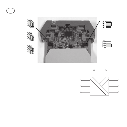
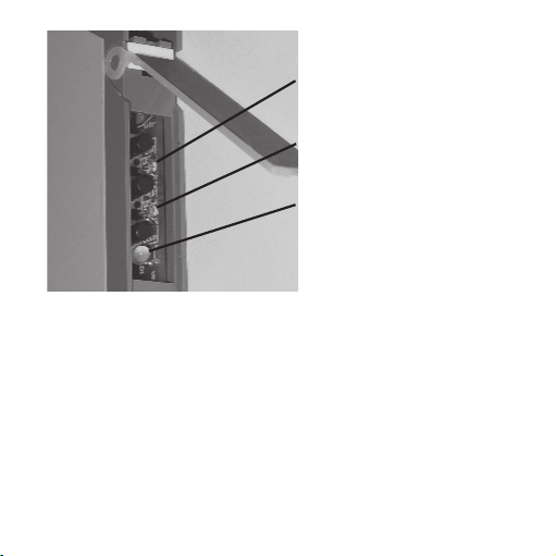
Voltage Output
Current Output
Current Input
Voltage Input
Loop Powered
(2-wire) Input
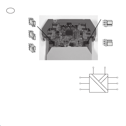
en
Input
PS
Out
V +
I +
pwr + pwr -
I +
Com
V +
Com
931S-C3C3J-DC
• Operation
General
The 931S-C3C3J-DC is a DIN rail mounted, signal Isolator/
Converter for Industrial Current/Voltage signals. It can be used
with 4-20 mA loop powered input devices using the Field Power
Supply provided.
Page 4

Current Test Points
WARNING
To monitor current signals, connect a multimeter (set to a suitable
milliamp range) across pins 2 (+) and 4 (−) for the inputs
or 8 (−) and 6 (+) for outputs.
Cleaning
The case can be wiped with a damp cloth. De-energize the unit
before cleaning.
• Installation
General
• Disconnect power prior to installation
• Installation only by Qualified personnel
• Follow all applicable local and national electrical codes
Locate the instrument in an area that is free from dust, moisture
and corrosive gases. Do not cover the ventilation holes at the side
of the case.
Page 5
Connections
For effective protection from electromagnetic noise, all signal
cables must be shielded, or located on conductive trays or in
conduits.
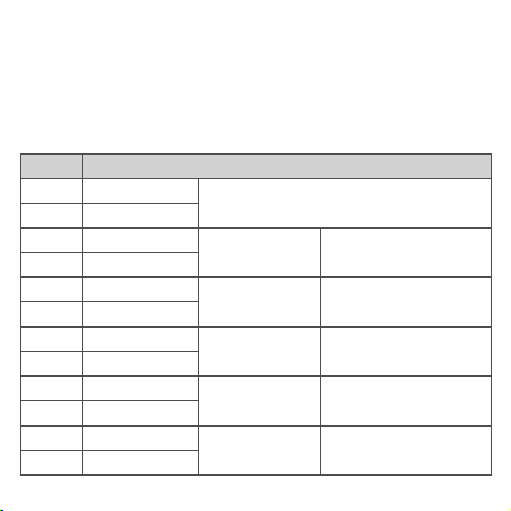
Strip wires to 7 mm from the ends. Use a suitable ferrule for multistranded wires (do not solder).
Term inal Signal
1 Supply +
7 Supply −
4 Voltage I nput +
3 Voltage I nput −
2 Curren t Input +
3 Curren t Input −
3 Device +
2 Device −
6 Voltage O utput +
5 Voltage O utput −
8 Curren t Output +
5 Curren t Output −
Power Supply
Voltage I nput
Curren t Input
Loop Powered Transmitter I nput
Voltage Outputs Output Typ e jumper to ‘Volts’
Current Outputs Output Type ju mper to ‘Cur rent’
Input Type Ju mper to ‘Vo lts’
Field Supply Jumper t o ‘Off ’
Input Type Ju mper to ‘Cur rent’
Field Supply Jumper t o ‘Off ’
Input Type Ju mper to ‘Cur rent’
Field Supply Jumper t o ‘On’
Page 6
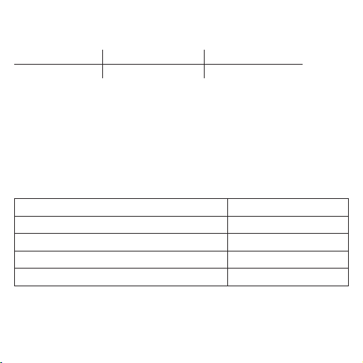
Power Supply Requirements
Power Supply Ratings are as follows:
Voltage Range Nominal Voltage Power
12 - 60 V DC 24 V DC 3 W (at 24 V DC)
Field power supply
The 931S-C3C3J-DC can power a loop powered transmitter input
using the integrated 24 V DC field power supply. A jumper setting
brings the power to the input terminals.
Power Supply recommendations:
24 VDC Output
15 W 1606-XLP15E
30 W 1606-XLP30E
50 W 1606-XLP50E
100 W 1606-XLP100E
120 W (5 A) 1606-XLE120E
Environmental conditions
Relative humidity: 0-90 % (non-condensing)
Ambient temperature: 0-60 °C
Page 7

• Setup
General
Inputs to the unit are analog current or voltage type. They are
rated for measuring category III signals with a voltage of 300 V
earth.
The input and output type are jumper selectable and their ranges
are set by the values used during calibration.
to
eff
• Calibration
General
All instruments are calibrated before leaving the factory and should
not need adjustment unless a change of range is required or until
the next scheduled calibration.
Equipment requirements
• An AB Bulletin 1606 DC Power Supply
• A digital multimeter (accurate to 0.05 mV and ±1 μA)
Procedure
1. Remove the instrument from the case and confirm that the
jumpers are in the correct positions for the input and output type
required.
Page 8

2. Connect up the instrument.
3. Press the UP and DOWN buttons together. The Status LED will
turn Red to indicate that the unit is in calibration mode.
4. Set the input source to the minimum value required, e.g., 4 mA
for 4-20 mA inputs.
5. Adjust the output value using the up and down keys until the
multimeter shows the output value required at minimum input,
e.g., 4 mA for a 4-20 mA output.
6. When you are satisfied with the output, press the ENT button.
The middle LED will switch on to indicate that you are calibrating
the maximum input and corresponding output values.
7. Set the input source to the maximum value required, e.g., 20 mA
for a 4-20 mA signal.
8. Adjust the output using the up and down keys until the output is
at the value required at maximum input, e.g., 20 mA for a 4-20
mA output.
9. Once all settings are completed press ENT twice. The ‘Ready
to save’ LED will switch on then turn off. After two seconds the
instrument will return to normal operation (with the Status LED
set to green). Otherwise press the ENT key and then the Up or
Down key to discard the calibration values.
Page 9
Ready to Save
Status:
Green for Run
Red For Calibrate Mode
Output Calibration
ENT
DOWN
UP
DIR 10000040362
(Version 00)
Page 10
Spannungsausgang
Stromausgang
Stromeingang
Spannungseingangt
Schleifengespeister
(2-Draht-)
Eingang
de
Eingang
SV
Aus
V +
I +
pwr + pwr -
I +
Com
V +
Com
931S-C3C3J-DC
• Betrieb
Allgemein
Der 931S-C3C3J-DC ist ein für die DIN-Schienenmontage
konzipierter Signaltrenner/-wandler, der für Strom-/
Spannungssignale im industriellen Bereich eingesetzt wird. Dank
seiner Feldstromversorgung ist er für die Speisung externer 4-20
mA-Sensoren geeignet.
Page 11

Stromabgriffspunkte
Zur Überwachung von Stromsignalen schließen Sie ein (auf einen
geeigneten Milliampere-Bereich eingestelltes) Multimeter wie folgt
an: Eingangsstrommessung an die Stifte 2 (+) und 4 (−);
Ausgangsstrom messung an die Stifte 8 (−) und 6 (+).
Reinigung
Das Gehäuse kann mit einem feuchten Tuch gereinigt werden.
Trennen Sie die Geräte von der Netzspannung, bevor Sie sie
reinigen.
• Installation
Allgemein
Die Installation dieser Geräte darf nur von speziell ausgebildetem
Fachpersonal unter Beachtung der in dieser Dokumentation
enthaltenen Informationen sowie der in dem jeweiligen Land
geltenden Bestimmungen für die elektrische Verdrahtung und
Sicherheitsvorschriften durchgeführt werden.
Montieren Sie das Instrument in einer staubfreien, trockenen
Umgebung, in der keine korrodierenden Gase auftreten. Die
Lüftungsöffnungen an der Gehäuseseite dürfen nicht abgedeck t
werden.
Page 12

Anschlüsse
Als effektiven Schutz vor elektromagnetischer Störeinstrahlung
müssen alle Signalleitungen eine Schirmung aufweisen oder in
leitfähigen Kabelkanälen bzw. in Rohren geführt werden.
Isolieren Sie die Anschlussleitung an beiden Enden auf 7
mm ab. Versehen Sie mehradrige Leiter mit einer geeigneten
Adernendhülse (nicht löten).
Page 13

Klemme Signal
1 Versorgung +
7 Versorgung −
4
3
2
3
3
2
6 Spannungsausgang +
5 Spannungsausgang −
8 Stromausgang +
5 Stromausgang −
Spannungseingang +
Spannungseingang −
Stromeingang +
Stromeingang −
Gerät +
Gerät −
Stromversorgung
Spannungseingang
Stromeingang
Schleifengespeister
Transmittereingang
Spannungsausgänge
Stromausgänge
Brüc ke für F unktion a ls Eingang
auf ‘Vol ts’ (Volt)
Brücke für Feldstromversorgung
auf ‘Of f’ (Aus)
Brüc ke für F unktion a ls Eingang
auf ‘Cur rent’ (S trom)
Brücke für Feldstromversorgung
auf ‘Of f’ (Aus)
Brüc ke für F unktion a ls Eingang
auf ‘Cur rent’ (S trom)
Brücke für Feldstromversorgung
auf ‘On’ ( Ein)
Brüc ke für F unktion a ls Ausgan g
auf ‘Vol ts’ (Volt)
Brüc ke für F unktion a ls Ausgan g
auf ‘St rom’ (Current)
Page 14

Anforderungen an die Stromversorgung
Für die Stromversorgung gelten folgende Leistungsdaten:
Spannungsbereich Nennspannung Leistung
12-60 V DC 24 V DC 3 W (bei 24 V DC)
Feldstromversorgung
Der 931S-C3C3J-DC ist in der Lage, über die integrierte 24 V DCFeldstromversorgung einen schleifengespeisten Sensor mit Strom
zu versorgen. Die Bereitstellung der Stromversorgung für die
Eingangsklemmen erfolgt über eine Brückeneinstellung.
Umweltbedingungen
Relative Feuchtigkeit: 0-90 % (nicht kondensierend)
Umgebungstemperatur: 0-60 °C
• Konguration
Allgemein
Das Gerät verfügt über analoge Strom- oder Spannungseingänge.
Diese sind für das Messen von Signalen der Kategorie III mit einer
Spannungsfestigkeit von 300 V
Die Funktion als Eingang bzw. Ausgang ist über eine Brücke
einstellbar. Die für sie zulässigen Bereiche werden durch die bei
der Kalibrierung verwendeten Werte festgelegt.
gegen Erde ausgelegt.
eff
Page 15

• Kalibrierung
Allgemein
Alle Geräte sind zum Zeitpunkt der Auslieferung kalibriert.
Eine Justierung ist in der Regel erst im Rahmen der nächsten
planmäßigen Kalibrierung notwendig, es sei denn, eine
Bereichsänderung ist erforderlich.
Anforderungen an die Betriebsmittel
• Eine geeignete DC-Stromversorgung
• Ein präzises Digitalmultimeter (mit einer Genauigkeit von 0,05
mV und ±1 μA)
Prozedur
1. Nehmen Sie das Instrument aus dem Gehäuse, und
vergewissern Sie sich, dass sich die Brücken in Abhängigkeit
der benötigten Funktion als Eingang bzw. als Ausgang an den
richtigen Positionen befinden.
2. Schließen Sie das Instrument an.
3. Drücken Sie die Tasten UP und DOWN gleichzeitig. Die Status-
LED leuchtet jetzt rot, um anzuzeigen, dass sich die Einheit im
Kalibriermodus befindet.
Setzen Sie die Eingangsquelle auf den benötigten Minimalwert,
4.
z. B. 4 mA bei 4-20 mA-Eingängen.
Page 16

5. Justieren Sie den Ausgangswert mit Hilfe der Tasten UP und DOWN,
bis das Multimeter den erforderlichen Ausgangswert bei minimalem
Eingang anzeigt, z. B. 4 mA bei einem 4-20 mA-Ausgang.
6. Wenn der erforderliche Ausgangswert erreicht ist, drücken Sie
die Taste ENT. Die mittlere LED leuchtet auf, um anzuzeigen,
dass Sie nun den maximalen Eingang und die entsprechenden
Ausgangswerte kalibrieren.
7. Setzen Sie die Eingangsquelle auf den benötigten Maximalwert,
z. B. 20 mA bei einem 4-20 mA-Signal.
8. Justieren Sie den Ausgang mit Hilfe der Tasten UP und DOWN,
bis der Ausgang den erforderlichen Maximalwer t erreicht hat, z. B.
20 mA bei einem 4-20 mA-Ausgang.
9. Wenn Sie mit dem Resultat zufrieden sind, drücken Sie ENT
zweimal. Die LED ‘Bereit für Speichern’ leuchtet auf und erlischt
dann wieder. Nach zwei Sekunden kehrt das Instrument in den
Normalbetrieb zurück (die Status-LED leuchtet grün). Andernfalls
drücken Sie die Taste ENT und dann die Taste UP oder DOWN, um
die Kalibrierwerte zu verwerfen.
Page 17

Speicherbereit
Status:
Grün bei Ausf.
Rot bei Kalibriermodus
Ausgangskalibrierung
ENT
DOWN
UP
DIR 10000040362
(Version 00)
Page 18

Sortie tension
Sortie courant
Entrée courant
Entrée tension
Entrée (2 fils)
alimentée en
boucle
fr
Input
PS
Out
V +
I +
pwr + pwr -
I +
Com
V +
Com
931S-C3C3J-DC
• Fonctionnement
Généralités
Le 931S-C3C3J-DC est un isolateur / convertisseur de signaux,
monté sur rail, pour les signaux courant / tension industriels. Il peut
être utilisé avec les unités d'entrée alimentées en boucle de courant
4-20 mA à l'aide de l'alimentation électrique de terrain fournie.
Page 19

Points de test du courant
Pour contrôler les signaux de courant, branchez un multimètre
(réglé sur une plage milliampères appropriée) aux bornes 2 (+) et 4
(−) pour les entrées, ou 8 (−) et 6 (+) pour les sorties.
Nettoyage
Le boîtier peut être nettoyé à l'aide d'un chiffon humide. Mettez
l'unité hors tension avant de procéder au nettoyage.
• Installation
Généralités
Ces unités doivent exclusivement être installées par un personnel
qualifié conformément aux informations figurant dans le présent
manuel, et toutes les règles nationales pertinentes en matière de
câblage électrique et de sécurité doivent être respectées.
Placez l'instrument dans une zone exempte de poussière,
d'humidité et de gaz corrosifs. Ne recouvrez pas les orifices de
ventilation se trouvant sur le côté du boîtier.
Connexions
Pour une protection efficace contre le bruit électromagnétique,
tous les câbles de signal doivent être blindés, ou posés dans des
chemins ou conduits de câbles conducteurs.
Page 20

Dénudez les extrémités de fil sur 7 mm. Utilisez un embout
approprié pour fils multibrins (ne soudez pas).
Borne Signal
1 Aliment ation +
7 Aliment ation −
4
3
2
3
3
2
6
5
8
5
Entrée t ension +
Entrée t ension −
Entrée c ourant +
Entrée c ourant −
Appare il +
Appare il −
Sort ie tension +
Sort ie tension −
Sort ie couran t +
Sort ie couran t −
Alimentation électrique
Entrée tension
Entrée c ourant
Entrée t ransmetteur
alimenté en boucle
Sort ies tensio n
Sort ies coura nt
Cavalier t ype d'entrée sur ‘Volts’
Cavalier al iment atio n de ter rain
sur ‘Of f’
Cavalier t ype d'e ntré e sur
‘Current’
Cavalier al iment atio n de ter rain
sur ‘Of f’
Cavalier t ype d'e ntré e sur
‘Current’
Cavalier al iment atio n de ter rain
sur ‘On’
Cavalier t ype de sortie sur
‘Volts’
Cavalier t ype de sortie sur
‘Current’
Page 21

Exigences relatives à l'alimentation électrique
Les caractéristiques nominales de l'alimentation électrique sont les
suivantes :
Plage de tension Tension nominale Puissance
12 - 60 V c.c. 24 V c.c. 3 W (à 24 V c.c.)
Alimentation électrique de terrain
Le 931S-C3C3J-DC est capable d'alimenter l'entrée de
transmetteurs alimentés en boucle à l'aide de l'alimentation
électrique de terrain 24 V c.c. intégrée. Un réglage à cavalier
achemine l'alimentation aux bornes d'entrée.
Conditions ambiantes
Humidité relative de l'air : 0-90 % (sans condensation)
Température ambiante : 0-60 °C
• Conguration
Généralités
Les entrées de l'unité sont du type courant ou tension analogique.
Elles sont conçues pour mesurer les signaux de catégorie III avec
une tension de 300 V
par rapport à la terre.
eff
Page 22

Les types d'entrée et de sortie peuvent être sélectionnés au moyen
de cavaliers et leurs plages sont définies par les valeurs utilisées
pendant l'étalonnage.
• Etalonnage
Généralités
Tous les instruments sont étalonnés avant de quitter l'usine et ne
devraient pas nécessiter de réglage avant le prochain étalonnage
programmé, à moins qu'un changement de plage ne soit
nécessaire.
Exigences concernant l'équipement
• Une alimentation électrique c.c. appropriée
• Un multimètre numérique précis (précision de 0,05 mV et ±1 μA)
Procédure
1. Retirez l'instrument du boîtier et vérifiez que les cavaliers sont
dans la bonne position pour les types d'entrée et de sortie
requis.
2. Branchez l'instrument.
3. Appuyez simultanément sur les boutons UP et DOWN. La LED
d'état s'allume en rouge afin d'indiquer que l'unité est en mode
étalonnage.
Page 23

4
. Réglez la source d'entrée à la valeur minimum requise, p. ex. 4
mA pour les entrées 4-20 mA.
5. Réglez la valeur de sortie à l'aides des touches UP et DOWN,
jusqu'à ce que le multimètre indique la valeur de sortie requise à
l'entrée minimum, p. ex. 4 mA pour une sortie 4-20 mA.
6. Si vous êtes satisfait de la sortie, appuyez sur le bouton ENT.
La LED centrale s'allume pour indiquer que vous êtes en
train d'étalonner l'entrée maximum et les valeurs de sortie
correspondantes.
7. Réglez la source d'entrée à la valeur maximum requise, p. ex. 20
mA pour un signal 4-20 mA.
8. Réglez la valeur de sortie à l'aides des touches UP et DOWN,
jusqu'à ce que la sortie se trouve à la valeur requise à l'entrée
maximum, p. ex. 20 mA pour une sortie 4-20 mA.
9. Si vous êtes satisfait des résultats, appuyez deux fois sur ENT.
La LED 'Prêt à enregistrer' s'allume, puis s'éteint. Après deux
secondes, l'instrument retourne à l'état de fonctionnement normal
(avec la LED d'état allumée en vert). Sinon, appuyez sur la touche
ENT, puis sur la touche UP ou DOWN pour rejeter les valeurs
d'étalonnage.
Page 24

Prêt à enregistrer
Etat :
vert pour run
rouge pour mode
étalonnage
Etalonnage sortie
ENT
DOWN
UP
DIR 10000040362
(Version 00)
Page 25

Salida de tensión
Salida de corriente
Entrada de
corriente
Entrada de
tensión
Entrada
alimentada
por bucle
(2 hilos)
es
Input
PS
Out
V +
I +
pwr + pwr -
I +
Com
V +
Com
931S-C3C3J-DC
• Funcionamiento
Información general
El 931S-C3C3J-DC es un aislador/convertidor de señal para
señales industriales de corriente/tensión diseñado para ser
montado en un carril DIN. Usando la fuente de alimentación
local que se suminstra con él, puede emplearse con dispositivos
alimentados por bucle de entrada 4-20 mA.
Page 26

Puntos de comprobación de la intensidad de corriente
Para monitorizar señales de corriente, conecte un multímetro (con
un rango de medida de miliamperios adecuado) entre los bornes 2
(+) y 4 (−) para las entradas o bien 8 (−) y 6 (+) para las salidas.
Limpieza
Use un paño húmedo para limpiar la carcasa. Desconecte el
dispositvo de la alimentación y asegúrese de que no está bajo
tensión antes de limpiarlo.
• Montaje
Información general
Estas unidades solo podrán ser montadas por personal
convenientemente cualificado, siguiendo las instrucciones que se
detallan en este manual y respetando la reglamentación nacional
vigente referente al cableado eléctrico y a la seguridad.
Emplace el instrumento en un lugar en que no esté expuesto a la
humedad, ni al polvo, ni a gases corrosivos. No tape los orificios
de ventilación situados en el lateral de la carcasa.
Page 27

Conexiones
Para conseguir una protección efectiva frente a las perturbaciones
electromagnéticas, todos los cables de señal deben estar
apantallados, o bien estar emplazados en bandejas portacables
de material conductor o en conductos apropiados.
Quite 7 mm de aislante en los extremos de los cables. Use una
virola adecuada para cables de varios hilos (sin soldar).
Page 28

Borne Señal
1 Aliment ación +
7 Aliment ación −
4 Entrada de tensión +
3 Entrada de tensión −
2 Entrada de cor-
3 Entrada de cor-
3 Dispos tivo +
2 Dispositivo −
6 Salida de t ensión +
5 Salida de t ensión −
8 Salida de c orriente +
5 Salida de c orriente −
riente +
riente −
Fuente de alimentación
Tensión de ent rada
Corriente de ent rada
Entrada del transmisor alimen tada por
bucle
Salidas de tensión
Salidas de corriente
Jumpe r (pue nte) de tip o de
entrad a en ‘Volt s’ (voltios)
Jumper (p uente) de la alimentación loc al a ‘Off’
Jumpe r (pue nte) de tip o de
entrad a en ‘Curre nt’ (corriente)
Jumper (p uente) de la alimentación loc al a ‘Off’
Jumpe r (pue nte) de tip o de
entrad a en ‘Curre nt’ (corriente)
Jumper (p uente) de la alimentación loc al a ‘On’
Jumpe r (pue nte) de tip o de
salida en ‘ Volts’ (voltios)
Jumpe r (pue nte) de tip o de
salida en ‘Current ’ (corriente)
Page 29

Especicaciones de la fuente de alimentación
Las características de la fuente de alimentación son las siguientes:
Rango de tensiones Tensión nominal Potencia
12 - 60 V CC 24 V CC 3 W (a 24 V CC)
Fuente de alimentación local
El 931S-C3C3J-DC puede alimentar la entrada alimentada
por bucle de un transmisor gracias a su fuente integrada de
alimentación local de 24 V DC. Configurando un jumper (puente)
se consigue alimentar los terminales de entrada.
Condiciones ambientales
Humedad relativa: 0-90 % (sin condensación)
Temperatura ambiente: 0-60 °C
Page 30

• Conguración
Información general
Las entradas de la unidad son de tipo análogico, bien de tensión
o de corriente. Están dimensionadas para medir señales de
categoría III con una tensión de 300 V
Se pueden seleccionar varios tipos de salida y de entrada
mediante conmutadores jumper (puente). Sus rangos quedan
determinados por los valores elegidos durante la calibración.
respecto a tierra.
eff
• Calibración
Información general
Todos los instrumentos han sido calibrados en fábrica y no
deberían necesitar recalibración alguna a menos que se cambie el
rango o hasta que se cumpla el plazo previsto para ello.
Equipamiento requerido
• Una fuente de alimentación adecuada de corriente continua.
• Un multímetro digital preciso (precisión de hasta 0,05 mV y
±1 μA)
Page 31

Procedimiento
1. Retire el instrumento de la carcasa y verifique que los jumpers
(puentes) están en las posiciones correctas correspondientes a
los tipos de entrada y salida requeridos.
2. Encienda el instrumento.
3. Pulse simultáneamente los botones UP y DOWN. El piloto LED
de estado se pone rojo para indicar que la unidad se encuentra
en modo de calibración.
4. Ajuste la fuente de entrada al valor mínimo requerido, p.ej. 4 mA
para entradas 4-20 mA.
5.
Ajuste el valor de salida usando las teclas UP y DOWN hasta que el
multímetro muestre el valor de salida que ha de corresponder a la
entrada mínima, p. ej. 4 mA para una salida 4-20 mA.
6. Cuando haya conseguido un ajuste satisfactorio de la salida, pulse
el botón ENT. El piloto LED del centro se enciende, lo cual indica
que a partir de ese momento se estará calibrando el nivel de
entrada máximo y sus valores correspondientes valores de salida.
7. Ajuste la fuente de entrada al valor máximo requerido, p.ej. 20 mA
para una señal 4-20 mA.
8. Ajuste el valor de salida usando las teclas UP y DOWN hasta que la
salida alcance el valor correspondiente al nivel máximo de entrada,
p. ej. 20 mA para una salida 4-20 mA.
Page 32

9. Cuando haya conseguido un resultado satisfactorio, pulse dos
Listo para guardar
Estado:
V e rde = func. normal
Rojo = modo calibración
Salida de calibración
ENT
DOWN
UP
veces ENT. Con ello se enciende el piloto LED "Listo para guardar"
y se apaga a continuación. Transcurridos dos segundos, el
instrumento vuelve al modo normal de funcionamiento (con el piloto
LED de status en color verde). Si no lo desea así, pulse el botón
ENT y a continuación el botón UP o el DOWN para rechazar los
valores de la calibración.
DIR 10000040362
(Version 00)
Page 33

Uscita di
tensione
Uscita di
corrente
Ingresso di
corrente
Ingresso di
tensione
Ingresso loop
di corrente
(a 2 fili)
it
Ingresso
PS
Out
V +
I +
pwr + pwr -
I +
Com
V +
Com
931S-C3C3J-DC
• Funzionamento
Generalità
Il 931S-C3C3J-DC è un convertitore/isolatore di segnale, montato
su rotaia DIN, per segnali di corrente/tensione industriali. Può
essere utilizzato per dispositivi con loop di alimentazione in
ingresso da 4-20 mA mediante l'alimentatore fornito in dotazione.
Page 34

Punti di prova corrente
Per monitorare i segnali di corrente, collegare un multimetro
(impostato su un campo milliamp adeguato) attraverso i pin 2 (+) e
4 (−) per gli ingressi oppure 8 (−) e 6 (+) per le uscite.
Pulizia
La custodia può essere pulita con un panno umido. Togliere
tensione alla unità prima di pulirla.
• Installazione
Generalità
Queste unità devono essere installate soltanto da personale
qualificato in conformità alle informazioni fornite nel presente
manuale e nel rispetto di tutte le relative normative nazionali
inerenti la sicurezza e i cablaggi elettrici.
Posizionare lo strumento in una zona esente da polvere, umidità
e gas corrosivi. Non coprire i fori di ventilazione sul lato della
custodia.
Collegamenti
Per un'efficace protezione da interferenze elettromagnetiche, tutti
i cavi per i segnali devono essere schermati oppure passare in
supporti conduttivi o in appositi canali.
Page 35

Spelare i cavi fino a 7 mm dalle estremità. Usare una boccola
adatta per cavi multipli (non saldare).
Morsetto Segnale
1 Aliment azione +
7 Aliment azione −
4 Ingres so di ten-
3 Ingres so di ten-
2 Ingres so di cor-
3 Ingres so di cor-
3 Dispositivo +
2 Dispositivo −
6 Uscita tensione +
5 Uscita tensione −
8 Uscita corrent e +
5 Uscita corrent e −
sione +
sione −
rente +
rente −
Alimentazione
Ingres so di tensio ne
Ingres so di corre nte
Ingre sso tras mett itore
loop alime ntazio ne
Uscite t ensione
Uscite c orrente
Jumpe r tipo di ingr esso su
‘Volt s’ (volt)
Jumper alim entato re su ‘Of f’
Jumpe r tipo di ingr esso su
‘Current’ (corrente)
Jumper alim entato re su ‘Of f’
Jumpe r tipo di ingr esso su
‘Current’ (corrente)
Jumper alim entato re su ‘On’
Jumper tip o di uscit a su
‘Volt s’ (volt)
Jumper tip o di uscit a su
‘Current’ (corrente)
Page 36

Requisiti alimentazione
I dati nominali dell'alimentazione sono i seguenti:
Campo di tensione Tensione nominale Potenza
12 - 60 V DC 24 V DC 3 W (a 24 V DC)
Alimentatore di campo
Il 931S-C3C3J-DC può fornire energia ad un trasmettitore con loop
di alimentazione utilizzando l'alimentatore incorporato da 24 V DC.
Un'impostazione del jumper porta l'energia ai morsetti di ingresso.
Condizioni ambiente
Umidità relativa: 0-90 % (senza condensa)
Temperatura ambiente: 0-60 °C
Page 37

• Setup
Generalità
Gli ingressi per l'unità sono di tipo a corrente o tensione analogica.
Sono regolati per la misurazione dei segnali di categoria III con una
tensione di 300 V
Il tipo di ingresso e di uscita sono selezionabili mediante jumper
ed i loro campi sono impostati in base ai valori utilizzati durante la
calibrazione.
a terra.
eff
• Calibrazione
Generalità
Tutti gli strumenti vengono calibrati prima di lasciare la fabbrica
e non necessitano di ulteriori regolazioni a meno che non sia
richiesta una modifica del campo di regolazione o fino alla
successiva calibrazione programmata.
Requisiti di equipaggiamento
• Un'alimentazione DC adatta
• Un multimetro digitale preciso (con precisione no a 0,05 mV e
±1 μA)
Page 38

Procedura
1. Estrarre lo strumento dalla custodia e confermare che i jumper
si trovano nelle posizioni corrette per i tipi di ingresso ed uscita
richiesti.
2. Collegare lo strumento.
3. Premere i tasti UP e DOWN insieme. Il LED di stato diventerà di
colore rosso per indicare che l'unità è in modalità di calibrazione.
4. Impostare la sorgente di ingresso al valore minimo richiesto, ad
es. 4 mA per ingressi da 4-20 mA.
5. Regolare il valore di uscita utilizzando i tasti up e down finché
il multimetro non mostra il valore di uscita richiesto all'ingresso
minimo, ad es., 4 mA per un'uscita da 4-20 mA.
6. Quando si è soddisfatti dell'uscita, premere il tasto ENT. Il
LED centrale si accenderà per indicare che si sta calibrando il
massimo ingresso ed i corrispondenti valori di uscita.
7. Impostare la sorgente di ingresso al valore massimo richiesto, ad
es. 20 mA per un segnale da 4-20 mA.
8. Regolare il valore di uscita utilizzando i tasti up e down finché
l'uscita non è al valore richiesto all'ingresso massimo, ad es. 20
mA per un'uscita da 4-20 mA.
Page 39

9. Se i risultati sono soddisfacenti, premere due volte il tasto
Pronto per
memorizzazione
Stato:
verde per Run
rosso per modalità
Calibrazione
Calibrazione uscita
ENT
DOWN
UP
ENT. Il LED "Pronto per memorizzazione" si accenderà e
quindi si spegnerà. Dopo due secondi lo strumento tornerà al
funzionamento normale (con il LED di stato sul verde). In caso
contrario premere il tasto ENT quindi il tasto UP o DOWN per
scartare i valori di calibrazione.
DIR 10000040362
(Version 00)
Page 40

DIR 10000040362
(Version 00)
 Loading...