

Page 1
Installation Instructions
Bulletin 842D DeviceNet MultiĆTurn Absolute Encoders
IMPORTANT: SAVE THESE INSTRUCTIONS FOR FUTURE USE.
Specifications
Electrical
Code Format Natural Binary
Code Direction CW or CCW (programmable)
Electrical Interface DeviceNet specification release 2.0
Operating Voltage 11ć25V DC (24V DC recommended)
Power Consumption 1.8W (75mA @ 24V DC)
Max # of Steps/Revolution 8192
Max # of Revolutions 8192
Position Forming Time 0.3msec
Delay on Power Up 1050msec
Preset Position Via covered rear button or DeviceNet
Mechanical
Angular Acceleration 5 x 10⁵ radians/sec
Moment of Inertia 35gcm
Operating Speed 6000 RPM at max shaft loading
Starting Torque 2.5Ncm (3.5oz-in)
Shaft Loading Axial 11lb (50N)
2
(5.0 x 10⁻⁴oz-in-sec2)
Radial 67lb (300N)
Electrical Connections
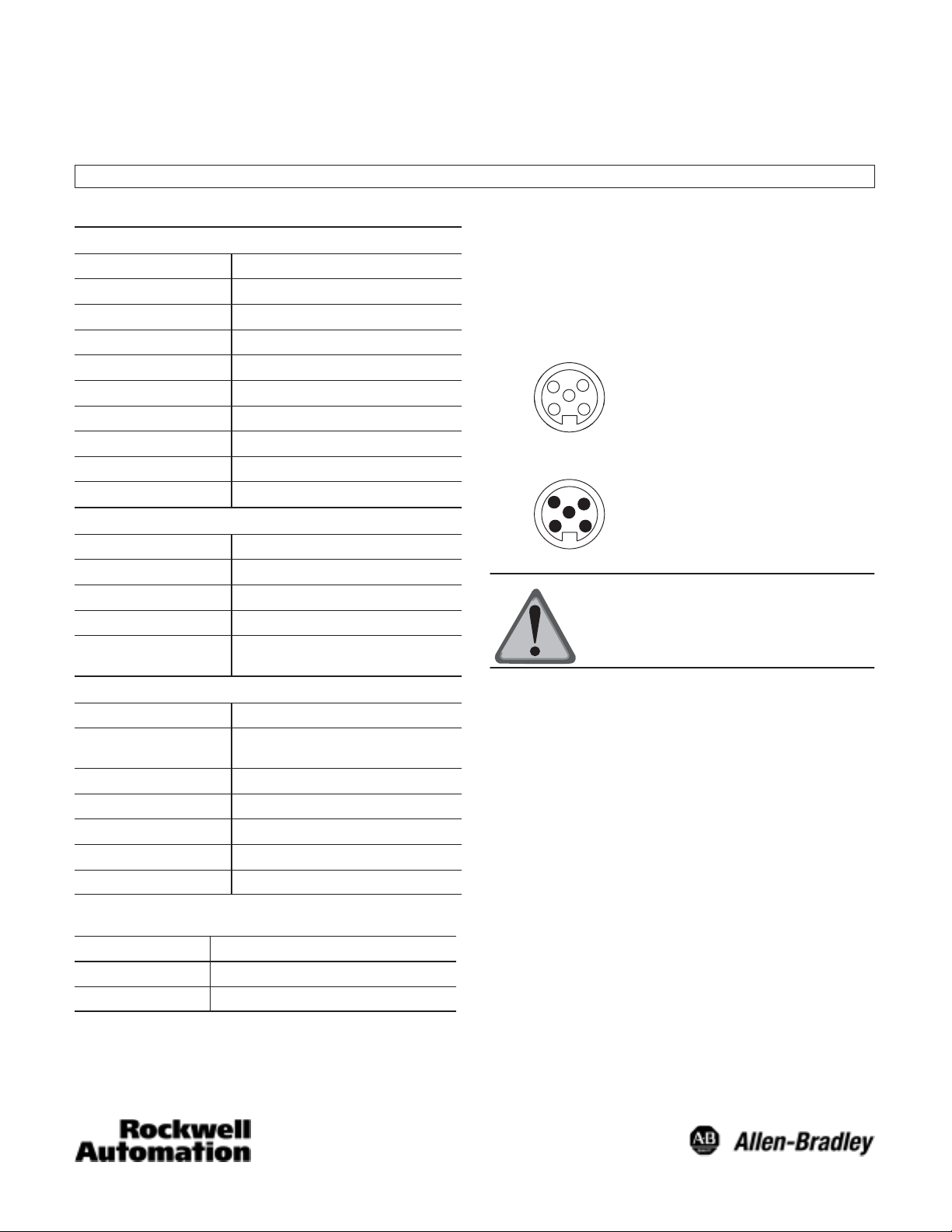
As shown in the selection guide, 842D DeviceNet encoders
are available with one 5-pin male micro quick-disconnect or
two 5-pin micro quick-disconnects (one male and one female).
Pin configurations are per the DeviceNet specifications as
follows.
Female Micro
4
3
5
2 1
Male Micro
4
3
5
21
2
1 Drain Bare
2 V+ Red
3 V- Black
4 CAN_H White
5 CAN_L Blue
ATTENTION: Wiring must be in
accordance with the National Electric
Code and applicable local codes and
ordinances.
Environmental
Housing Aluminum
Temperature
Humidity 98% noncondensing
Protection NEMA Type 4, 13, IP66 (IEC 529)
Vibration 20g/10-2000Hz
Approximate Weight 0.91kg (2lbs)
-20_C to 85_C (-4_F to +185_F)ĊOperating
-40_C to 125_C (-40_F to +257_F)ĊStorage
Shock 100g/6msec
Selection Guide
Catalog Number Electrical Connection
842D-60131331BDA One 5 pin male micro QD
842D-60131331BXA Two 5 pin micro QDs (one male & one female)
Manuals and Software
Commissioning the 842D DeviceNet encoder requires an
Electronic Data Sheet (EDS) file be loaded on the system
running the bus management software. Typically, the EDS file
is loaded on a computer running RSNetWorx for DeviceNet.
The EDS file may be downloaded from our website at:
www.ab.com/networks/eds/. Simply select “DeviceNet,”
“RA-Miscellaneous” and press the “Search” button. Select the
842D encoder. This will allow you to download file
00010073002E0400.eds. The User’s Manual may also be
downloaded from our website at:
www.ab.com/manuals/sn/ER.htm.
Saving Parameter Values to EEPROM
Unless parameter values are saved to EEPROM, changes
made to parameter values will not be restored when power is
cycled. In RSNetWorx parameter values are saved to
EEPROM via the Class Instance Editor. Please see the User’s
Manual for further details.
1
Page 2
Mounting Instructions
1. Be sure to select the proper size flexible coupling clamp to
mate to the encoder shaft, e.g., 845–FC–*–*. See
Encoder Accessories in Sensors catalog.
ATTENTION: Do not rigidly connect
the encoder shaft to the machine; this
will cause premature failure of the
encoder or machine bearings. Always
use a flexible coupling.
Flexible Shaft Couplings
Angle
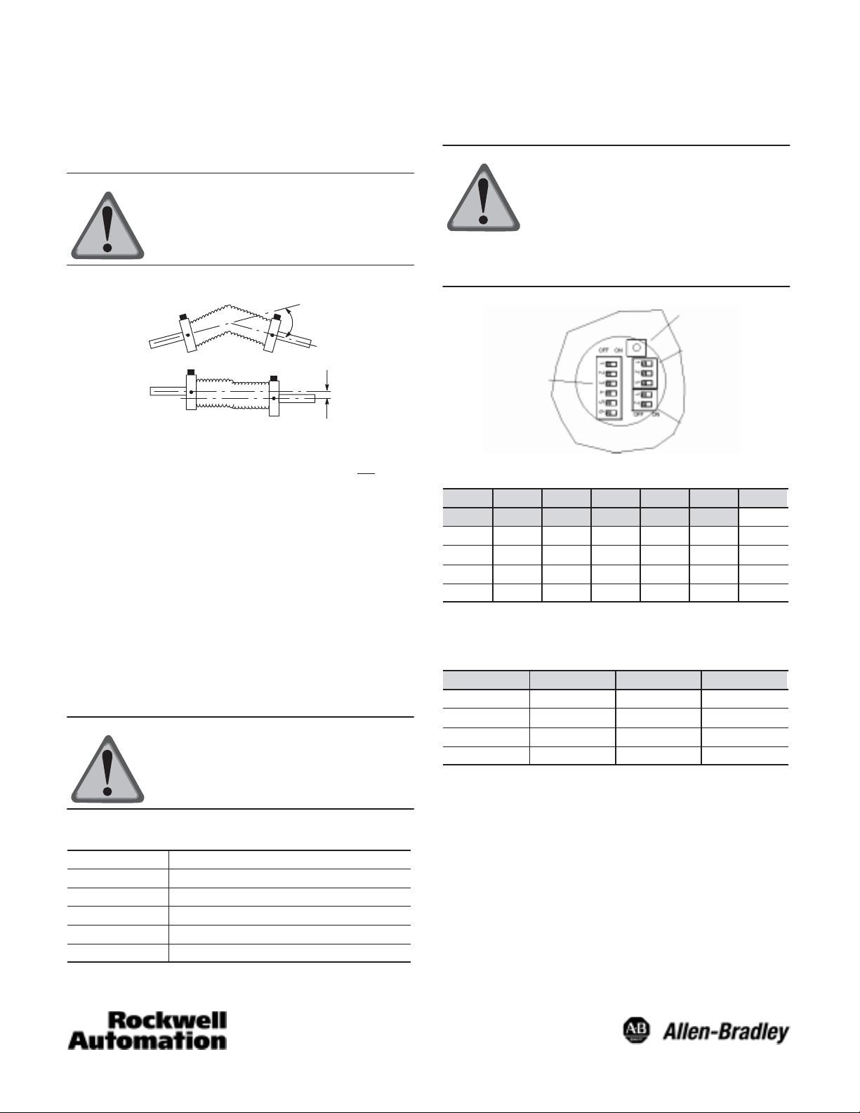
Setting the MAC–ID (node address),
Baud Rate and Bus Termination Dip Switches
ATTENTION: Connecting this product
to an operational DeviceNet network
with improperly set DIP switches
usually will cause the entire network to
stop communicating. Baud rate setting
must be the same as the rest of the
network and the MAC–ID must be
different than the rest of the network.
Preset Position
Button
Baud Rate
Parallel
OffĆSet
2. Use the dimension drawings to determine the encoder
mounting hole locations.
3. Slide the flexible coupling onto the shaft, but do not
tighten
the set screws.
4. Mount the encoder and tighten with three size M4
mounting screws (not supplied).
5. Center the flexible coupling and tighten the set screws.
6. Rotate the machine slowly and verify that the flexible
coupling is not deforming beyond specifications.
7. Align machine to its mechanical zero or home position.
Remove slotted cover located on the back of the encoder
and press the preset position button to change the position
value to the preset value (the factory preset value is zero).
Replace cover.
Preset
To preset the position of the encoder, remove the slotted cover
from the back of the encoder and press the button inside.
ATTENTION: Pressing the preset position
button results in a change of position
reading. This can cause unexpected
motion which could result in damage to
the product, equipment, or personal injury.
Mac-ID
Bus
Termination
MAC-ID
DIP-6 DIP-5 DIP-4 DIP-3 DIP-2 DIP-1 Address
5
2
0 0 0 0 0 0 0
0 0 0 0 0 1 1
... ... ... ... ... ... ...
1 1 1 1 1 1 63
4
2
3
2
2
2
1
2
0
2
0 = DIP switch is OFF
1 = DIP switch is ON
Baud Rate
DIP-3 DIP-2 DIP-1 Baud rate
X 0 0 125 kBaud
X 0 1 250 kBaud
X 1 0 500 kBaud
X 1 1 125 kBaud
X = don’t care
0 = DIP switch is OFF
1 = DIP switch is ON
Indicator
LED Status
Off Not connected not onĆline
Green Blinking Active but not allocated by master
Green Steady Active and allocated by master
Red Blinking Minor fault and/or connection interrupt
Red Steady Critical communication fault
2
Page 3

Bus Termination
The recommended method for connecting DeviceNet products
is to run a “trunk line” with 120 ohm resistors connected at
each end. DeviceNet products are then connected as “drops”
along the length of the trunk line. In this configuration, the
internal termination resistor of the 842D should not be used
and the bus termination DIP switches should be off.
When 842D encoders are connected in a “daisy chain”
configuration, the internal termination resistor may be used on
the end positions only. In this configuration, the end 842D(s)
should have their bus termination DIP switches turned on.
Further details on termination resistors can be found in
publication DN–6.7.2 DeviceNet Cable System Planning and
Installation Manual.
ATTENTION: If you do not use
terminating resistors as described here
and in publication DN–6.7.2, the
DeviceNet cable system will not
operate properly.
ON
12
Bus termination
1 and 2 OFF: not active
1 and 2 ON: active
Note: Remote setting of the DIP switches via a Node
Commissioning Tool is not supported at this time.
3
Page 4

Dimensions—mm (in)
35.94/35.98
(1.415/1.416)
∅53.8
(2.12)
8.8/9.2
(0.34/0.37)
9.98/9.99
(0.392/0.393)
18
(0.71)
18/20
(0.71/0.79)
∅59.5
(2.34)
3 (0.12)
10 (0.39)
6 (0.24)
27.8
(1.09)
105.8 (4.16)
Diagnostic
LEDs
Screw Cover for
DIP Switches and
Reset Button
Single QD Single QD
65 (2.56)
M4 x 7 (0.28) deep on
a 48.0 (1.89) diameter
bolt circle 3 places
120_ apart
120_
18.8
(0.74)
70
(2.756)
13
(0.51)
35_
∅
"
48 0.1
(1.89)
Diagnostic
LEDs
Screw Cover for
DIP Switches and
Reset Button
Double QD Double QD
65 (2.56)
M4 x 7 (0.28) deep on
a 48.0 (1.89) diameter
bolt circle 3 places
120_ apart
Visit our web site at:
4
http://www.ab.com/sensors
35_120_
∅
"
48 0.1
(1.89)
Publication 75008–146–01(C)
Document 910 000 103 871
July 2002
Printed in USA
 Loading...