

Page 1
Installation Instructions
Bulletin 842A Absolute Encoders
IMPORTANT: SAVE THESE INSTRUCTIONS FOR FUTURE USE.
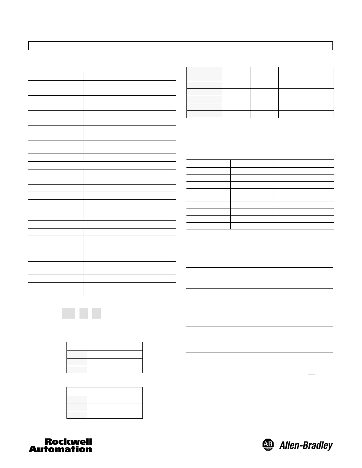
Specifications
Electrical
Code Format Gray or Natural Binary
Code Direction CW or CCW
Symmetry 40% to 60%
Operating Voltage 10–32V DC
Power Requirements 150mA @ 5V (no load)
Max # of Steps/Revolution 8192
Max # of Revolutions 8192
Position Forming Time 0.5msec
Delay on Power Up 1050msec
Clock +, Clock - , Data +,
CW/CCW “L”active(L=0--0.9V,H=1.9–24V))
Synchronous Serial Interface (SSI) RS--422
Data -
Mechanical
Angular Acceleration 5x10⁵radians/sec
Moment of Inertia 5x10
Maximum Working Speed 6000 RPM at max shaft loading
Maximum Operating Speed 12,000 RPM
Starting Torque 3.5oz in (2.5 Ncm)
Shaft Loading Axial 11lb (50N)
-- 4
Radial 67lb (300N)
2
oz-in-sec2(35 gcm2)
Environmental
Housing Aluminum
Temperature
Humidity 98% noncondensing
Protection NEMA Type 4, 13, IP67 (IEC 529): static shaft
Vibration 20g/58--2000Hz, 1.5mm displacement (10--58Hz)
Approximate Weight 0.5kg (18oz)
-- 2 0 _Cto85_C(--4_Fto185_F) operating
-- 4 0 _Cto100_C(--40_Fto212_F) max. working
-- 4 0 _Cto125_C(--40_Fto257_F) storage
NEMA Type 4, 13, IP66 (IEC 529): moving shaft
Shock 100g/6msec
Selection
842A — 31 G B
a
b c
a
Code T ype
Code Description
31 36mm Pilot, 10mm Shaft
56 50mm Pilot, 6mm Shaft
b
Code T ype
Code Description
G Gray Code
N Natural Binary
c
A-B
Code
A 8192 12--24 2048 1--11
B 4096 13--24 4096 1--12
C 2048 14--24 8192 1--13
D 4096 13--24 512 4--12
E 4096 13--24 256 5--12
Electrical Connections
The 842A comes with an M23 connector. The mating
connector, 845--12P, or pre-wired cable and connector
assembly 845--CA--G--* must be ordered separately. See
Encoder Accessories in the Sensors catalog.
Function
DC Return 1 Ground
Data + 2 SSI
Clock + 3 SSI
DC + Input 8 10--32V DC
Reset 9
Data -- 10 SSI
Clock -- 11 SSI
CW/CCW 12
Reset to zero is enabled when Pin 9 is momentarily connected to DC+ Input.
When pin 12 is connected to DC + (or left floating), the 842A will count UP when
the shaft is turned CW when looking at the shaft. When pin 12 is connected to DC
return, the 842A will count UP when the shaft is turned in the CCW direction when
looking at the shaft.
IMPORTANT: Wiringmustbeinaccordancewiththe
Mounting Instructions
1. Be sure to select the proper size flexible coupling clamp to
mate to the encoder shaft, e.g., 845--FC--*--*. See
Encoder Accessories in Sensor catalog.
IMPORTANT: Do not rigidly connect the encoder shaft to
2. Use the dimension drawings to determine the encoder
mounting hole locations.
3. Slide the flexible coupling onto the shaft, but do not
the set screws.
4. Mount the encoder and tighten with three size M4
mounting screws (not supplied).
5. Center the flexible coupling and tighten the set screws.
6. Rotate the machine slowly and verify that the flexible
coupling is not deforming beyond specifications.
7. Align machine to its mechanical zero or home position.
Remove slotted cover located on the back of the encoder
and press the Reset button to make the encoder count
zero. Replace cover.
Pulses
Per Rev.
SSI Bits
MSB- LSB
No. of
Revs.
SSI Bits
MSB- LSB
Pin Number Description
150mA no load
See below
National Electric Code and applicable local
codes and ordinances.
the machine; this will cause premature
failure of the encoder or machine bearings.
Always use a flexible coupling.
tighten
Page 2
Reset
To reset the output of the encoder to zero turns and zero shaft
position, remove the slotted cover from the back of the
encoder and press the button inside. This can also be done by
momentarily connecting pin 9 to DC+ Input.
ATTENTION: Pressing the reset button results in a
change of position reading. This can cause
unexpected motion which could result in damage to
the product, equipment, or personal injury.
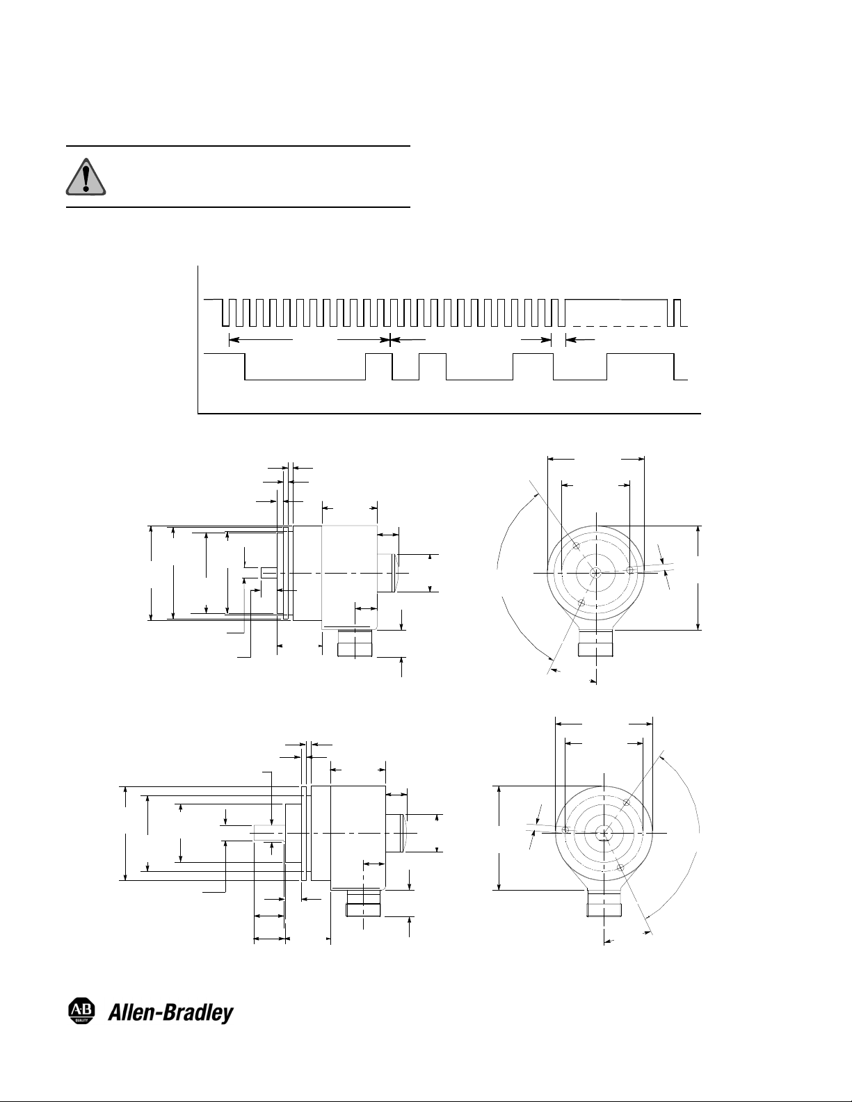
Timing Diagrams
1314151617
BITS
842--SPA
CLOCK +
842A
423 6579 1819202122
1
1
0
TURNS
1
11
10
8
12
SSI
DATA +
VAL UE
0
0000000001 1 11 11100 00000
1
Dimensions—mm
3 (0.12)
3 (0.12)
59.5
(2.34)
58
(2.28)
49.94/49.98
(1.966/1.967)
(0.235/0.236)
5.98/5.99
9.0/11.0
(0.35/0.43)
51.5
(2.03)
4 (0.16)
27.8
(1.09)
34
(1.34)
13.5
(0.53)
13
(0.51)
22
(0.87)
Below is an example of a timing diagram as viewed on an
oscilloscope. In this example, the 842A--31NB, a binary code
output with 4096 pulses per revolution and 4096 turns is
connected to an 842--SPA serial to parallel interface adaptor.
The 842--SPA generates an SSI clock burst of pulses. On the
positive slope of the start pulse, the 842A--31NB begins to
transmit its position data. In the example below, the
842A--31NB is returning 100000000011 (2051 Turns) and
001100000111 (775 position). After the data is sent, the output
remains in a low state for a short duration, then goes to a high
state in anticipation of the next SSI clock burst. The Error Bit
(bit 25) is normally zero. If there is a power interruption (e. g. -low voltage) during data transmission, the Error Bit is set high.
23
25
24
1
...
SHAFT POSITION
ERROR BIT
...
60 (2.36)
42±0.1
(1.65)
M4
3Plcs
66
(2.60)
24
(0.94)
120_
Typ
7 (0.275) deep
25_
Bulletin 842A--56**
59.5
(2.34)
53.8
(2.12)
35.94/35.98
(1.415/1.416)
8.8/9.2
(0.34/0.37)
4 (0.16)
9.98/9.99
(0.392/0.393)
(0.71/0.79)
18
(0.71)
18/20
10
(0.39)
27.8
(1.09)
3 (0.12)
34
(1.34)
13.5
(0.53)
13
(0.51)
22
(0.87)
Bulletin 842A--31**
Visit our web site at:
http://www.ab.com/sensors
24
(0.94)
66
(2.60)
M4
3Plcs
7 (0.28) deep
60 (2.36)
48±0.1
(1.89)
120_
Typ
25_
Publication 75008--131 Ver 06
Document 910 990 103 488
February 2013
PrintedinUSA
 Loading...