

Page 1
Solid-State
Level Sensors
USER MANUAL
840E
Page 2
Important User Information
WARNING
IMPORTANT
ATTENTION
SHOCK HAZARD
BURN HAZARD
Solid-state equipment has operational characteristics differing from those of electromechanical equipment. Safety
Guidelines for the Application, Installation and Maintenance of Solid-State Controls (Publication SGI-1.1 available
from your local Rockwell Automation sales office or on-line at http://www.ab.com/manuals/gi) describes some
important differences between solid-state equipment and hard-wired electromechanical devices. Because of this
difference, and also because of the wide variety of uses for solid-state equipment, all persons responsible for applying
this equipment must satisfy themselves that each intended application of this equipment is acceptable.
In no event will Rockwell Automation, Inc. be responsible or liable for indirect or consequential damages resulting
from the use or application of this equipment.
The examples and diagrams in this manual are included solely for illustrative purposes. Because of the many variables
and requirements associated with any particular installation, Rockwell Automation, Inc. cannot assume responsibility
or liability for actual use based on the examples and diagrams.
No patent liability is assumed by Rockwell Automation, Inc. with respect to use of information, circuits, equipment,
or software described in this manual.
Reproduction of the contents of this manual, in whole or in part, without written permission of Rockwell
Automation, Inc. is prohibited.
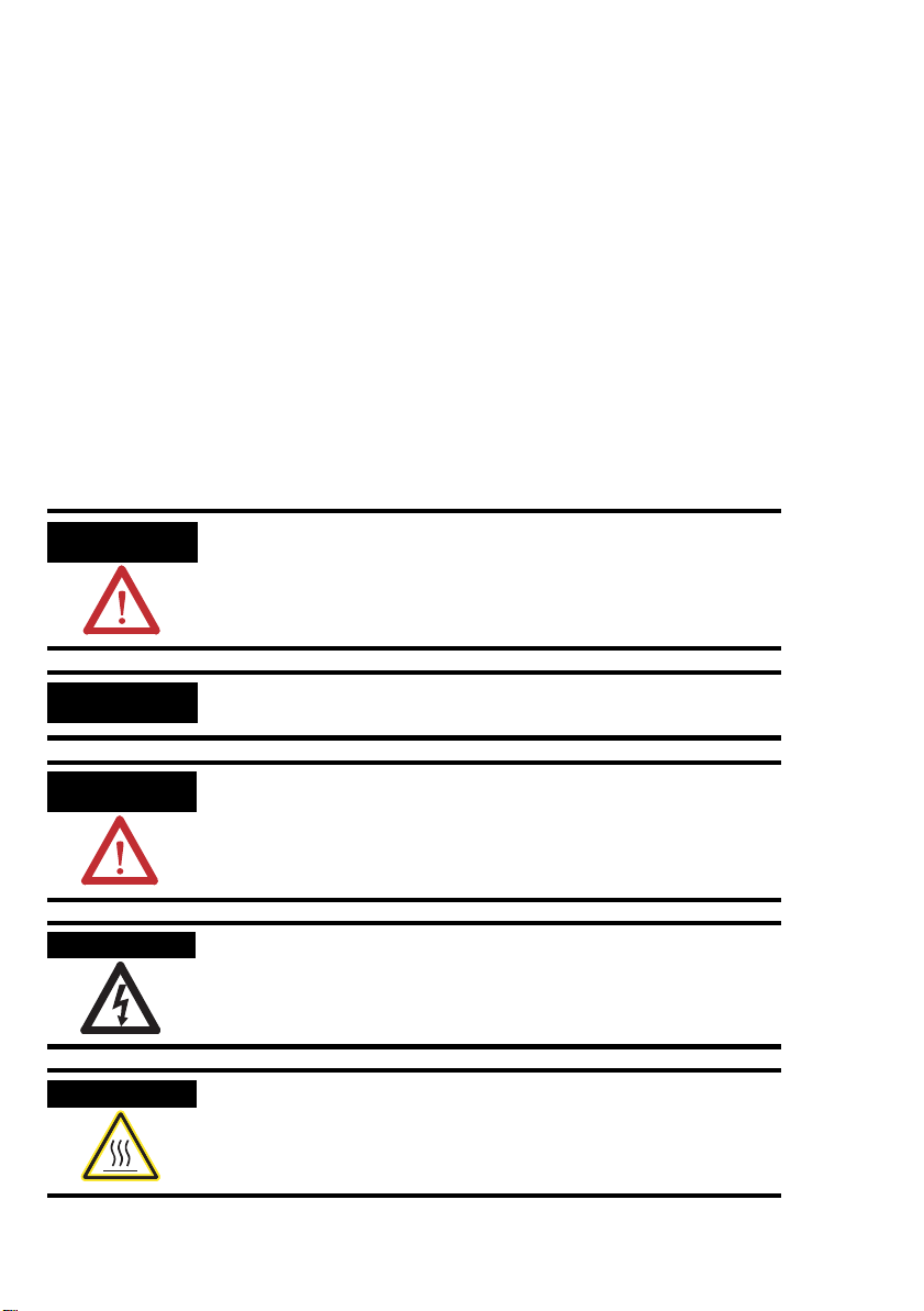
Throughout this manual, when necessary we use notes to make you aware of safety considerations.
Identifies information about practices or circumstances that can cause an
explosion in a hazardous environment, which may lead to personal injury or
death, property damage, or economic loss.
Identifies information that is critical for successful application and understanding
of the product.
Identifies information about practices or circumstances that can lead to personal
injury or death, property damage, or economic loss. Attentions help you:
• identify a hazard
•avoid a hazard
• recognize the consequence
Labels may be located on or inside the equipment (e.g., drive or motor) to alert
people that dangerous voltage may be present.
Labels may be located on or inside the equipment (e.g., drive or motor) to alert
people that surfaces may be dangerous temperatures.
Page 3

Table of Contents
Table of Contents
1 Safety Instructions . . . . . . . . . . . . . . . . . . . . . . . . . . . . . . .2
1.1 Designated Use . . . . . . . . . . . . . . . . . . . . . . . . . . . . . . . . . . . . . . . . . . . . . . 2
1.2 Installation, Commissioning, and Operation . . . . . . . . . . . . . . . . . . . . . . . . 2
1.3 Operational Safety . . . . . . . . . . . . . . . . . . . . . . . . . . . . . . . . . . . . . . . . . . . . 2
1.4 Return . . . . . . . . . . . . . . . . . . . . . . . . . . . . . . . . . . . . . . . . . . . . . . . . . . . . . . 2
2 Product Identification. . . . . . . . . . . . . . . . . . . . . . . . . . . . . 3
3 Installation . . . . . . . . . . . . . . . . . . . . . . . . . . . . . . . . . . . . . . 4
3.1 Dimensions . . . . . . . . . . . . . . . . . . . . . . . . . . . . . . . . . . . . . . . . . . . . . . . . . . 4
3.2 Installation Instructions. . . . . . . . . . . . . . . . . . . . . . . . . . . . . . . . . . . . . . . . . 6
4 Wiring . . . . . . . . . . . . . . . . . . . . . . . . . . . . . . . . . . . . . . . . . 10
4.1 DC PNP Version with M12 Connector. . . . . . . . . . . . . . . . . . . . . . . . . . . . . 10
4.2 AC Version with Valve Connector NPT 1/2 . . . . . . . . . . . . . . . . . . . . . . . . . 12
4.3 Functional Test . . . . . . . . . . . . . . . . . . . . . . . . . . . . . . . . . . . . . . . . . . . . . . . 14
5 Technical Data. . . . . . . . . . . . . . . . . . . . . . . . . . . . . . . . . . 15
5.1 Power Supply. . . . . . . . . . . . . . . . . . . . . . . . . . . . . . . . . . . . . . . . . . . . . . . . 15
5.2 Performance Characteristics . . . . . . . . . . . . . . . . . . . . . . . . . . . . . . . . . . . . 15
5.3 Operating Conditions. . . . . . . . . . . . . . . . . . . . . . . . . . . . . . . . . . . . . . . . . . . 16
1
Page 4
Safety Instructions
1 Safety Instructions
1. 1 Designated Use
The Bulletin 840E is a level switch for all kinds of fluids and is used in tanks, containers and
pipelines. The device has been safely built with state-of-the-art technology and meets the
applicable requirements and EC Directives. It can, however, be a source of danger if used
incorrectly or for anything other than the designated use.
1. 2 Installation, Commissioning, and Operation
Only personnel familiar with these types of products and associated machinery should plan or
implement the installation, start-up, configuration, and subsequent maintenance of the
Bulletin840E level switch.
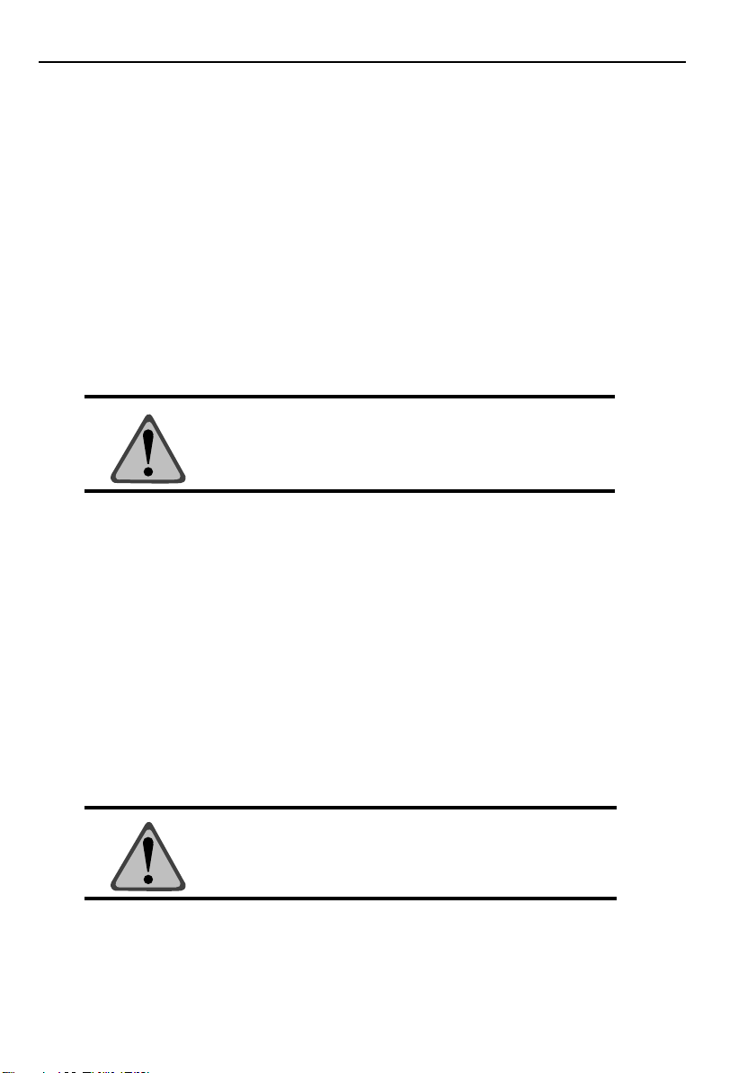
ATTENTION: Installation and commissioning must be
carried out by qualified individuals. Failure to comply may
result in personal injury or equipment damage.
1. 3 Operational Safety
• Functional safety
The Bulletin 840E level switches were developed according to the standards EN60068 and
EN 61326.
• Hazardous areas
The Bulletin 840E is not approved for use in intrinsic safety (hazardous area) applications.
1. 4 Return
Before returning a device to Rockwell Automation, be sure to remove all fluid residue. This is
particularly important if the fluid is a health hazard, e.g. flammable, toxic, caustic, carcinogenic,
etc.
ATTENTION: Do not return a measuring device if you are not
absolutely certain that all traces of hazardous substances have
been removed, e.g. substances which have penetrated crevices
or diffused through plastic.
2
Page 5
Product Identification
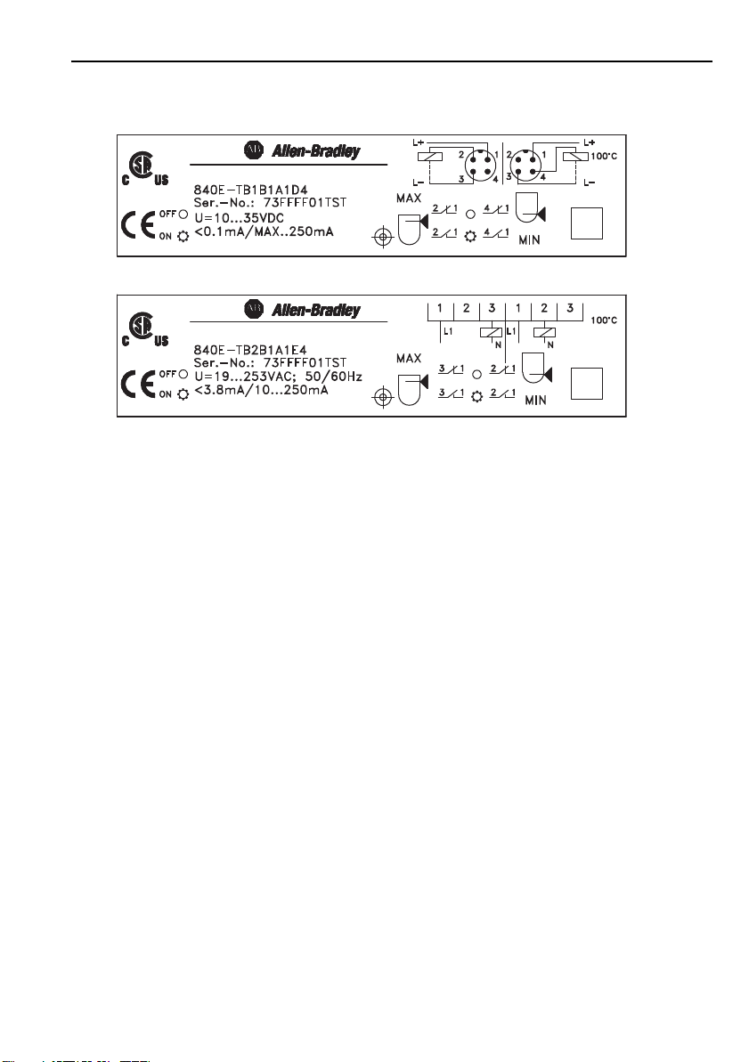
2 Product Identification
Figure 2.1: Nameplate
Notes:
• Specifications and ratings may differ from those shown in Figure 1, depending on particular
model. Refer to product nameplate or catalog for actual ratings and specifications.
• The series number indicates the version of the switch. A change in the series letter does not
have any effect on the compatibility.
3
Page 6
Installation
3 Installation
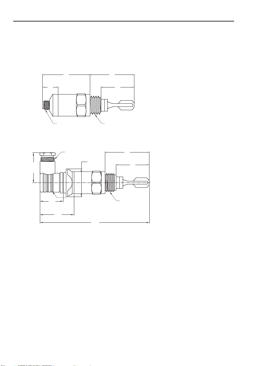
3. 1 Dimensions
3.1.1 1/2 in. NPT and 3/4 NPT Process Connection [mm (in.)]
68.5
(2.70)
22.7
(0.89)
M12
1/2 in. NPT
VALVE
40
(1.57)
36
(1.42)
51.5
(2.03)
Figure 3.1: NPT Dimensions
Ø40
(Ø1.57)
161
(6.34)
63.9
(2.52)
47.9
(1.89)
1/2 in. NPT
OR
3/4 in. NPT
63.9
(2.52)
47.9
(1.89)
1/2 in. NPT
OR
3/4 in. NPT
4
Page 7

3.1.2 G 1/2 Process Connection [mm (in.)]
22.7
(0.89)
68.5
(2.70)
63.9
(2.52)
38
(1.50)
16
(0.63)
G 1/2
M12
63.9
(2.52)
38
(1.50)
16
(0.63)
161
(6.34)
G 1/2
40
(1.57)
Ø40
(Ø1.57)
51.5
(2.03)
36
(1.42)
1/2 in. NPT
VALVE
840E-TB2B3A1E4 G 1/2 2-WIRE 19…253V AC 100 °C 1/2 NPT Valve Connector
840E-TB2B2A1E4 3/4 in. NPT 2-WIRE 19…253V AC 100 °C 1/2 NPT Valve Connector
840E-TB2B1A1E4 1/2 in. NPT 2-WIRE 19…253V AC 100 °C 1/2 NPT Valve Connector
840E-TB1B3A1D4 G 1/2 3-WIRE PNP 10…35V DC 100 °C M12 Connector
840E-TB1B2A1D4 3/4 in. NPT 3-WIRE PNP 10…35V DC 100 °C M12 Connector
840E-TB1B1A1D4 1/2 in. NPT 3-WIRE PNP 10…35V DC 100 °C M12 Connector
Description
Catalog Number
Figure 3.2: G 1/2 Dimensions
Installation
3.1.3 Product Selection
5
Page 8

Installation
Ra < 3.2 µm
3. 2 Installation Instructions
3.2.1 Handling
Figure 3.3: Hold by the housing, not by the sensor fork
Figure 3.4: Do not bend, shorten or lengthen.
6
Page 9

3.2.2 Mounting Examples
A
B
B
A
A
~13 (0.5)
~10.5 (0.41)
~3 (0.12)
~2 (0.08)
~30 (1.2)
mm (in.)
Installation
Figure 3.5: A = Switchpoint, B = Switching Hysteresis
7
Page 10

Installation
BDA
C
A
B
C
D
= 0...10000 mm²/s
= 0... 2000 mm²/s
minimum
DN 50 (2.0)
[mm (in.)]
( 0...15.50 in²/s)
( 0...3.10 in²/s)
3.2.3 Viscosity and Build-up
Figure 3.6: Take into account viscosity and build-up.
8
Page 11

3.2.4 Sensor Fork Alignment
!
OFF
ON
O
F
F
O
N
= 0...10000 mm²/s
= 0... 2000 mm²/s
( 0...15.50 in²/s)
( 0...3.10 in²/s)
Figure 3.7: Align Sensor Fork (note mark)
Installation
9
Page 12

Wiring
889D-F4AC-2
14
(0.56)
31.8
(1.25)
889D-R4AC-2
4 Wiring
4. 1 DC-PNP Version with M12 Connector
Operating Mode MAX (NC Contact) Operating Mode MIN (NO Contact)
12
12
R
R = External Load
I = 250 mA Maximum
U = 10...35 V DC
2
1
3
4
L– L+
0.5 A
1 - Brown
2 - White
3 - Blue
14
14
L– L+
Figure 4.1: DC-PNP Wiring
4.1.1 Mating Cables [mm (in.)]
2 m (6.5 ft) PVC Cable
with 4-pin micro (M12x1) connector and
ratcheted epoxy-coated zinc coupling nut.
Catalog number: 889D-F4AC-2
2 m (6.5 ft) PVC Cable
with 4-pin micro (M12x1) right-angle
connector and ratcheted epoxy-coated zinc coupling nut.
Catalog number: 889D-R4AC-2
2
1
3
4
R
(0.56)
1 - Brown
3 - Blue
4 - Black
0.5 A
47
(1.85)
14
10
Note: Other cable lengths are available and shielded cables may be required for some analog
output applications – refer to the On-Machine Connectivity catalog (publication
#M115-CA001A-EN-P) for additional information.
Page 13

4.1.2 DC-PNP Operation
...
U– (DC)
1
MAX MIN
2
1
2
1
Wiring
4
4
1
U
< 3 V < 3 V
IIII
U
(PNP)
L+
–L+ –L+ – L+ –
Green
Figure 4.2: DC-PNP Operation
Green light ON:
Sensor is connected to power supply and operational
Yellow light ON:
Sensor is immersed in liquid
Red light ON:
Overload or short-circuit in load circuit
- Rectify the short circuit
- Reduce maximum load current to below 250 mA
Green light OFF:
Error: No power supply
- Check plug, cable and power supply
Red light flashing:
Internal sensor error or sensor corroded
-Replace device
Red
Yellow
Light On
Light Off
< 100 µA< 100 µA
++
11114224
11
Page 14

Wiring
1
3
0.5 A
L1
R
13
13
12
12
Operating Mode MAX Operating Mode MIN
PE
(Ground)
N
>19 V
12
3
0.5 A
L1
R
PE
(Ground)
N
>19 V
R = External Load
I = 250 mA Maximum
U = 19...253V AC
1Brown
2Blue
3 Black
GND Yellow/Green
4. 2 AC Version with Valve Connector NPT 1/2
Figure 4.3: AC Wiring.
4.2.1 Mating Cables
Optional cordset 2 m (6.5 ft) DIN valve. Catalog number: 889V-RZ3ABE-2
12
Page 15

4.2.2 AC Operation
MAX MIN
50...60 Hz
L1
V21<V21<
U
< 4 mA< 4 mA
U
N
L1
N
L1
N
L1
N
11112332
IIII
U~(AC)
1
3
1
3
1
2
1
2
Light On
Light Off
Green
Red
Wiring
Figure 4.4: AC Operation
Green light ON:
Sensor is connected to power supply and operational
Red light ON:
Mode of operation MAX (overfill protection): sensor is immersed in liquid
Mode of operation MIN (dry running protection): sensor is immersed in liquid
Green light OFF:
Error: No power supply
- Check plug, cable and power supply
Red light flashing:
Error: Overload or short-circuit in load circuit
- Rectify the short circuit
- Reduce maximum load current to below 250 mA
Error: Internal sensor error or sensor corroded
-Replace device
13
Page 16

Wiring
MAX
MIN
MAX
MAX
–>
–>
–>
.2.1
.2.1
.2.1
MIN
Green Yellow Green Yellow
Green Yellow Green Yellow
Green Red Green Red
4. 3 Functional Test
Use test magnet supplied with the sensor to test level switch functionality.
Figure 4.5: Functional Test
14
Page 17

5 Technical Data
5. 1 Power Supply
DC-PNP with M12 connector
10...35 V DC Supply voltage
< 825 mW Power consumption
< 15 mA Current consumption
AC with NPT 1/2 valve connector
19...253 V AC Supply voltage
< 810 mW Power consumption
< 3.8 mA Current consumption
5. 2 Performance characteristics
Switching delay 0.5 s when covering
1.0 s when free
Resolution < 0.5 mm (0.02 in.)
Maximum error 13.0 +/- 1 mm (0.51 in. +/- 0.04 in.)
Repeatability +/- 0.5 mm (+/- 0.02 in.)
Hysteresis 3.0 +/- 0.5 mm (0.12 in. +/- 0.02 in.)
Settling time < 2 s
Technical Data
Reference operating conditions
Ambient temperature: 23 °C (73 °F)
Process pressure: 14.5 psi
Medium: Water
Medium density: 1
Medium temperature: 23 °C (73 °F)
Installation from above
Density setting: > 0.7 SGU
15
Page 18

Technical Data
32
(0)
32
(0)
T
P
212
(100)
158
(70)
140 (60)
104 (40)
68 (20)
-40
(-40)
-40
(-40)
86
(30)
140
(60)
T
a
°F (°C)
°F (°C)
176*
(80)*
122
(50)
-13**
(-25)**
-4
(-20)
-4
(-20)
5. 3 Operating Conditions
Ambient temperature range -40...+70 °C (-40...+158 °F)
Process temperature range -40...+100 °C (-40...+212 °F)
Storage temperature range -40...+85 °C (-40...+185 °F)
Shock resistance EN 60068-2-27 (30 g)
Vibration resistance EN 60068-2-64
Process pressure -14.5...580 psi
Degree of protection NEMA 4X (IP66/67) DC - M12 connector
IP65 AC - Valve connector
Media Liquid
Density > 0.7 SGU
Viscosity 1...10 000 cSt
Gas content Stagnant mineral water
Solids content < 5 mm(0.20 in.) diameter
16
Page 19

Back Cover
Page 20

Pub. No. 10000061888 Ver 0.0
© 2009 Rockwell Automation. Printed in the U.S.A
September 16, 2009
 Loading...