

Page 1
Solid-State
Flow Sensors
USER MANUAL
839E
Page 2
Important User Information
Because of the variety of uses for the products described in this publication, those responsible for the
application and use of this control equipment must satisfy themselves that all necessary steps have been
taken to assure that each application and use meets all performance and safety requirements, including
any applicable laws, regulations, codes and standards.
Reproduction of the contents of this copyrighted publication, in whole or part, without written permission
of Rockwell Automation, is prohibited.
Throughout this manual we use notes to make you aware of safety considerations:
The illustrations, charts, sample programs and layout examples shown in the guide are intended solely for
purposes of example. Since there are many variables and requirements associated with any particular
installation, Rockwell Automation does not assume responsibility or liability (to include intellectual property
liability) for actual use based upon the examples shown in this publication.
Rockwell Automation publication SGI-1.1, Safety Guidelines for the Application, Installation and
Maintenance of Solid-State Control (available from your local Rockwell Automation sales office), describes
some important differences between solid-state equipment and electromechanical devices that should be
taken into consideration when applying products such as those described in this publication.
It is recommended that you save this user manual for future use.
Identifies information about practices or circumstances that can cause an explosion in
a hazardous environment, which may lead to personal injury or death, property
damage, or economic loss.
Identifies information that is critical for successful application and understanding of
the product.
Identifies information about practices or circumstances that can lead to personal
injury or death, property damage, or economic loss. Attentions help you identify a
hazard, avoid a hazard, and recognize the consequences.
SHO CK H AZAR D
Labels may be on or inside the equipment (for example, drive or motor) to alert people
that dangerous voltage may be present.
BUR N HA ZARD
Labels may be on or inside the equipment (for example, drive or motor) to alert people
that surfaces may reach dangerous temperatures.
WA RN IN G
IMP ORTA NT
AT TE NT IO N
Page 3

Table of contents
839E Solid-State Flow Sensors User Manual
Safety instructions . . . . . . . . . . . . . . . . . . . . . . . . . . . . . . . . 2
Designated use. . . . . . . . . . . . . . . . . . . . . . . . . . . . . . . . . . . . . . . . . . . . 2
Installation, commissioning and operation . . . . . . . . . . . . . . . . . 2
Operational safety. . . . . . . . . . . . . . . . . . . . . . . . . . . . . . . . . . . . . . . . . 2
Return . . . . . . . . . . . . . . . . . . . . . . . . . . . . . . . . . . . . . . . . . . . . . . . . . . . . 2
Product identification . . . . . . . . . . . . . . . . . . . . . . . . . . . . . 3
Installation . . . . . . . . . . . . . . . . . . . . . . . . . . . . . . . . . . . . . . . 4
Dimensions . . . . . . . . . . . . . . . . . . . . . . . . . . . . . . . . . . . . . . . . . . . . . . . 4
Process connection. . . . . . . . . . . . . . . . . . . . . . . . . . . . . . . . . . . . . . . . 5
Installation instructions. . . . . . . . . . . . . . . . . . . . . . . . . . . . . . . . . . . . 6
Wiring . . . . . . . . . . . . . . . . . . . . . . . . . . . . . . . . . . . . . . . . . . . . . . . . . . . . 8
Operation . . . . . . . . . . . . . . . . . . . . . . . . . . . . . . . . . . . . . . . 10
On-site programming . . . . . . . . . . . . . . . . . . . . . . . . . . . . . . . . . . . . 10
Programming with personal computer and ReadWin 2000 19
Accessories . . . . . . . . . . . . . . . . . . . . . . . . . . . . . . . . . . . . . . 21
Configuration kit with ReadWin . . . . . . . . . . . . . . . . . . . . . . . . . . . 21
Troubleshooting . . . . . . . . . . . . . . . . . . . . . . . . . . . . . . . . . 22
Error and warning codes. . . . . . . . . . . . . . . . . . . . . . . . . . . . . . . . . . 22
Repair. . . . . . . . . . . . . . . . . . . . . . . . . . . . . . . . . . . . . . . . . . . . . . . . . . . . 23
Disposal. . . . . . . . . . . . . . . . . . . . . . . . . . . . . . . . . . . . . . . . . . . . . . . . . . 23
Change status (release) . . . . . . . . . . . . . . . . . . . . . . . . . . . . . . . . . . . 23
Technical data . . . . . . . . . . . . . . . . . . . . . . . . . . . . . . . . . . . 24
Power supply. . . . . . . . . . . . . . . . . . . . . . . . . . . . . . . . . . . . . . . . . . . . . 24
Output. . . . . . . . . . . . . . . . . . . . . . . . . . . . . . . . . . . . . . . . . . . . . . . . . . . 24
Operating conditions. . . . . . . . . . . . . . . . . . . . . . . . . . . . . . . . . . . . . 25
Pub #10000004735 Ver 03, May 2012 1
Page 4

839E Solid-State Flow Sensors User Manual
AT TEN TIO N
Safety instructions
Designated use
The Bulletin 839E is a flow switch for measurement and monitoring of mass flow rates in
industrial processes. The device has been safely built with state-of-the-art technology and
meets the applicable requirements and EC Directives. It can, however, be a source of
danger if used incorrectly or for anything other than the designated use.
Installation, commissioning and operation
Only personnel familiar with these types of products and associated machinery should
plan or implement the installation, start-up, configuration, and subsequent maintenance
of the Bulletin 839E flow switch. Failure to comply may result in personal injury and/or
equipment damage.
Operational safety
• Funtional Safety
The 839E flow switch was developed according to standard IEC 61010.
• Ex-area
The 839E is not approved for use in Ex-areas.
Return
Before returning a device to Rockwell Automation, be sure to remove all fluid residue. This
is particularly important if the fluid is a health hazard, e.g. flammable, toxic, caustic,
carcinogenic, etc.
Do not return a measuring device if you are not absolutely
certain that all traces of hazardous substances have been
removed, e.g. substances which have penetrated crevices
or diffused through plastic.
2 Pub #10000004735 Ver 03, May 2012
Page 5
839E Solid-State Flow Sensors User Manual
839E-DA1BA1A3D4
53009401032
Flow (0.03…3m/s)
–40°F < T < 185°F
IP65
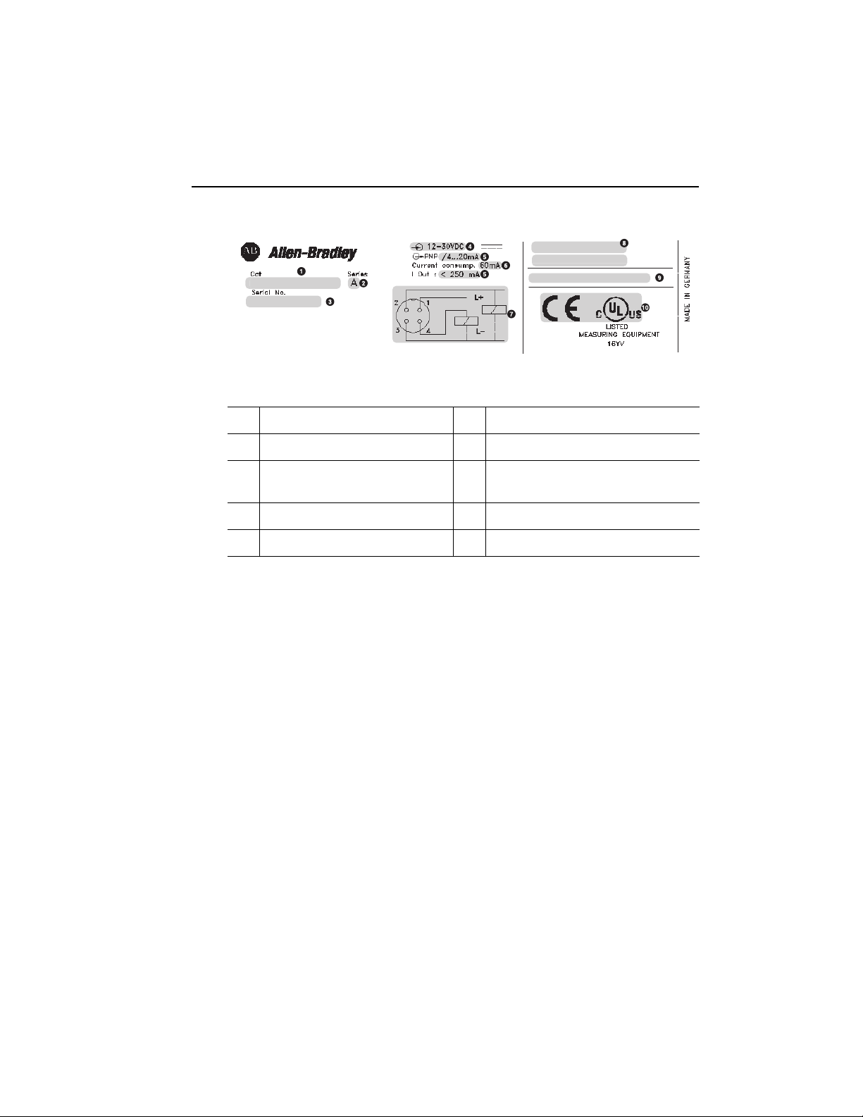
Product identification
Figure 1 Explanation of the nameplate — see Table below
1 Catalog number 6 Current consumption
2 Series letter 7 Wiring diagram
3 Serial number 8
Flow rate and ambient temperature
range
4 Operating voltage 9 Enclosure rating/ingress protection
5 Output 10 Approvals
Notes:
• Specifications and ratings may differ from those shown in Figure 1, depending on
particular model. Refer to product nameplate or catalog for actual ratings and
specifications.
• The series number indicates the version of the switch. A change in the series letter does
not have any effect on the compatibility—see “Change status” section.
• Approvals inlcude 3A authorized for models configured with sanitary adaptors.
Pub #10000004735 Ver 03, May 2012 3
Page 6
839E Solid-State Flow Sensors User Manual
M12 x 1
38.7 (1.52)
6 (0.24) Dia.
24 (0.95)
38.5 (1.515) Dia.
42.3 (1.66) Dia.
6 (0.24) Dia.
97.1
(3.82)
42.1
(1.657)
LL
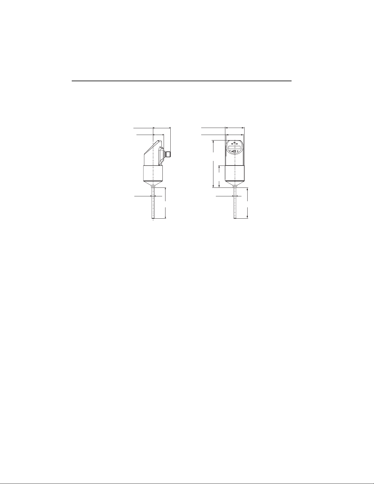
Installation
Dimensions
Figure 2 Dimensions [mm (in.)]
Version L with 30 and 100 mm (1.18 and 3.94 in.)
M 12x1 connector as per IEC 60947-5-2
4 Pub #10000004735 Ver 03, May 2012
Page 7
839E Solid-State Flow Sensors User Manual
2
L
L
1
A B C
43.5 (1.71) dia.
50.5 (1.99) dia.
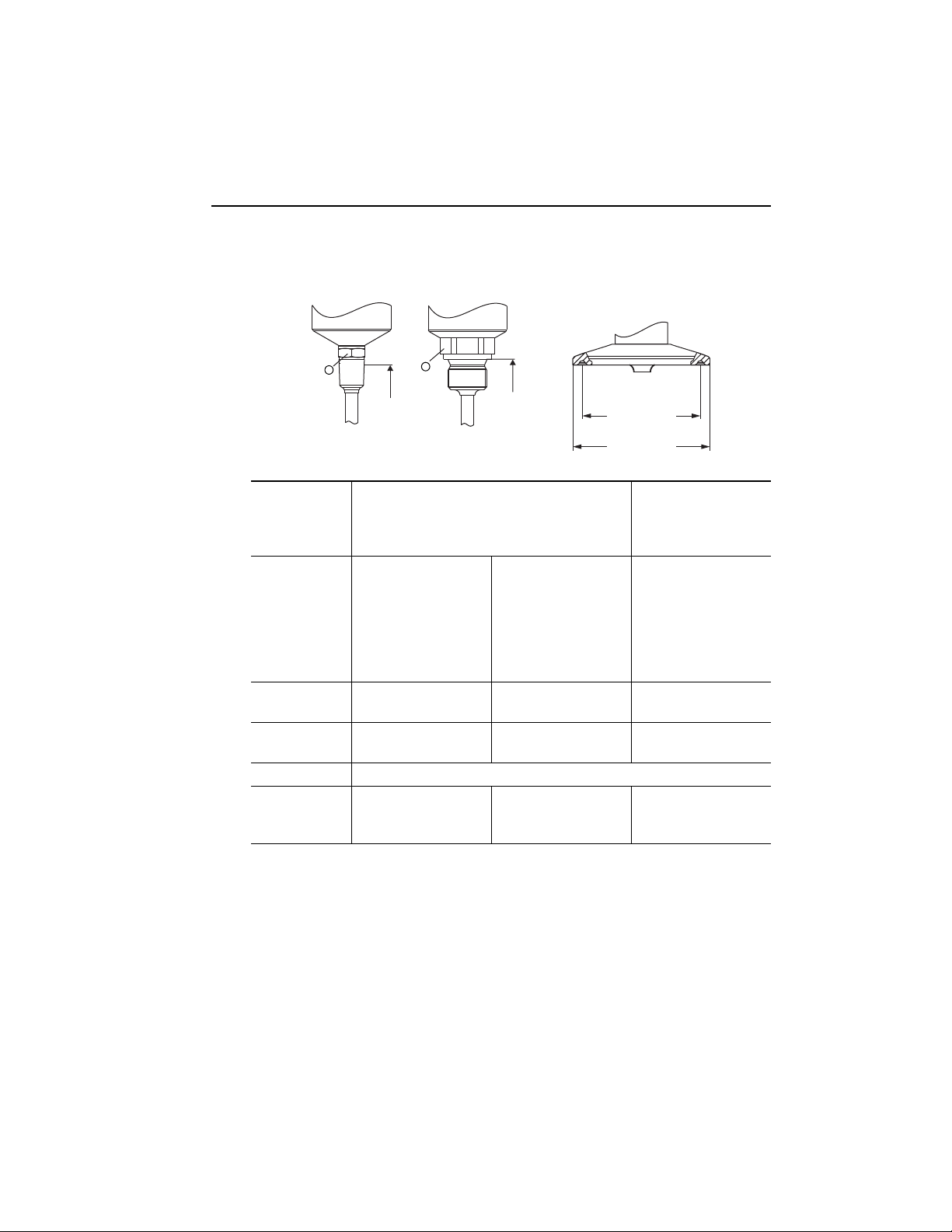
Process connection
The following table illustrates the versions of 839E.
Measurement and
Field of
application
Process
connection
Thread Length L114.3 mm (0.56 in.)
Thread Length L25.8 mm (0.23 in.)
Measuring and monitoring of mass flow rates
Item A
Version with thread
process connection
ANSI ¼-in. NPT
(1 = AF14) and ½-in.
NPT
(1 = AF27)
Item B
Version with thread
process connection
G ¼ (2 = AF14) and
G½
(2 = AF27) as per ISO
228
12 mm (0.47 in.)
19 mm (0.75 in.)
8.1 mm (0.32 in.)
14 mm (0.55 in.)
— —
Sensor length L Version L with 30 and 100 mm (1.18 and 3.94 in.)
Operational
range
Liquids from 0.03 to
3.0 m/s (0.1 to
9.84ft/s)
monitoring, mass flow
rates in sanitary
processes
Version with
50.8 mm (2 in.) clamp
or 25.4…38.1 mm
(1…1.5in.)
Item C
—
Pub #10000004735 Ver 03, May 2012 5
Page 8
839E Solid-State Flow Sensors User Manual
1
V
m
L
AT TEN TIO N
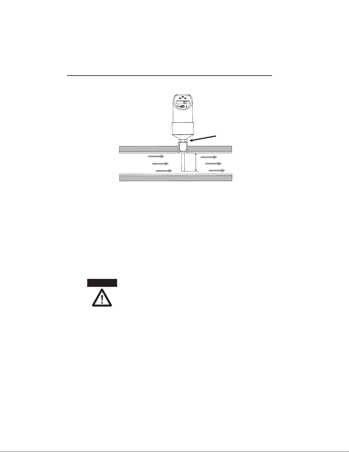
Installation instructions
Figure 3 Installing Bulletin 839E (example). Sensor length L is completely immersed in the flow
profile.
Mounting instructions:
• Any orientation
• The on-site display can be rotated electronically 180° — see “Operation” section.
• The housing can be rotated up to 310° for optimal readability and ease of wiring.
• Minimum sensor immersion length: L ≥ 10 mm (0.4 in.)
• The sensor tip should not touch the pipe wall.
• If used in a vertical pipe, the flow should be ascending.
• For a horizontal pipe, install sensor from top if pipe is completely filled with medium.
Otherwise, install sensor from side to ensure complete length of sensor is in the medium.
Do not turn the device into the process connection thread
at the housing. Always install the device at the
hexagonal-head bolt (refer to Figure 3, detail 1). Use a
suitable open-ended wrench for this task.
Note!
For correct flow measurement, the complete length of the sensor must be immersed in the
fully developed flow profile.
6 Pub #10000004735 Ver 03, May 2012
Page 9
839E Solid-State Flow Sensors User Manual
AT TEN TIO N
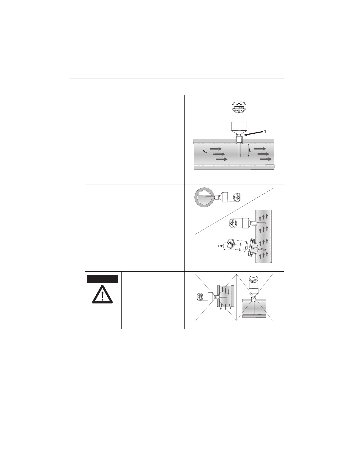
Installation instructions
Installation conditions
Note!
The sensor requires a fully developed flow profile for correct monitoring. For this reason,
steadying sections (5x DN) must be provided in the pipe after a pump, pipe bend, internal
fittings and cross-sectional changes.
Do not turn the device into the process connection thread
at the housing. Always install the device at the spanner flats
(Figure 4, item 1). Use a suitable open-ended wrench for
this task (see table of page 5).
• The onsite display can be rotated electronically 180°, see “Onsite operation” section.
• The upper housing section can be rotated mechanically up to 310°.
Pub #10000004735 Ver 03, May 2012 7
Page 10
839E Solid-State Flow Sensors User Manual
AT TEN TIO N
Wiring
• The sensor tip should be completely
surrounded by medium.
• Position the sensor tip in the area of
maximum fluid velocity (pipe center).
• Minimum sensor immersion length:
L1 ±10 mm.
Orientation:
• For horizontal pipes: lateral installation.
Note!
Installation from above (see Figure 4) only if
the pipe is completely filled with medium
during operation.
• For vertical pipes: installation in the
ascending pipeline.
• Installation of 839E by min. 3° inclination,
because of self draining.
Figure 4 Installation conditions
Figure 5 Correct orientation
• Do not install in down
pipes open towards the
end.
• The sensor tip should
never touch the pipe
wall.
Figure 6 Incorrect installation
8 Pub #10000004735 Ver 03, May 2012
Page 11

839E Solid-State Flow Sensors User Manual
4
R2
L+
L-
4…20 mA
3
12
4
R2R1
L+
L-
3
12
A1
A2
889D-R4AC-2
889D-F4AC-2
DC voltage version with M12 connector
Figure 7 DC voltage version with M12 connector
Bulletin 839E with M12x1 connector
A1: PNP switch outputs R1 and R2
A2: PNP switch output with 4…20 mA analog output
Mating cables
2 m (6.5 ft) PVC cable with 4-pin micro
(M12x1) connector and ratcheted
epoxy-coated zinc coupling nut.
Catalog number: 889D-F4AC-2
2 m (6.5 ft) PVC cable with 4-pin micro
(M12x1) right-angle connector and
ratcheted epoxy-coated zinc coupling nut.
Catalog number: 889D-R4AC-2
Note: Other cable lengths are available and
shielded cables may be required for some
analog output applications — refer to the
On-Machine Connectivity catalog for
additional information.
Pub #10000004735 Ver 03, May 2012 9
Page 12

839E Solid-State Flow Sensors User Manual
Operating ke y
Communications jac k
f or personal computer
Digital displa y
Y ello w LEDs f or s witching states
LED on = s witch closed
LED off = s witch open
LED for status
Green = ok
Red = error
Red/green blinking = warning
E
22.07
bar
Operation
On-site programming
The Bulletin 839E is programmed via three push buttons. The digital display and the light
emitting diodes (LEDs) assist in the navigation through the operating menu.
Figure 8 Location of operating keys and display elements
Background illumination of the digital display:
– White = OK status
– Red = alarm/error status
10 Pub #10000004735 Ver 03, May 2012
Page 13

839E Solid-State Flow Sensors User Manual
AT TEN TIO N
Navigating through the programming menu
Figure 9 Navigating through the programming menu
A Function group selection
B Function selection
➊ Enter the programming menu:
- Press and hold the E key for longer than 3 sec.
➋ Once in programming mode (BASE will be displayed), toggle between the Function
groups with the + and - keys
➌ To enter the Function group, press the E key
➍ Enter or change parameters with the + or - key.
- Then press the E key to return to the “Function” option
➎ Press the E key several times to return to the “Function group”
➏ Jump back to the measuring position (Home position)
- Then press the E key for longer than 3 sec.
➐ To save changes, choose YES or NO with the + or - key
- Confirm with the E key
Changes take effect only when you choose YES when asked
to save the data.
Pub #10000004735 Ver 03, May 2012 11
Page 14

839E Solid-State Flow Sensors User Manual
Navigating the “Learn” function
Figure 10 Navigating the “Learn” function using the Calibration (CAL) function group as an
example
➊ Select the HIF (Learn High Flow) or LOWF (Learn Low Flow) function with the E key
➋ Select the “RUN” function with the + key, learn function is initialized
➌ Select the “WAIT” function with the + key, press for longer than 2 sec.
➍ Accept (“learn”) the current measured value after approx. 10 sec. - “OK” appears on the
display
➎ If “NOK” (not OK) appears on the display after 60 sec., no current measured value was set
➏ Return to the CAL function group (Home position) with the E key
Notes!
1. Programming buttons [E], [-], and [+] may need to be pressed and held for several
seconds before displaying the expected response.
2. When performing a calibration the 839E may require up to 60 seconds to learn the high
or low flow rate. The display will indicate “WAIT” during the learn process.
3. After configuring the 839E to the desired settings, press and hold the [E] key until
“SAVE” appears; press the [+] or [-] key until “YES” appears. Press and hold the [E] key
until “SAVE” appears. Depending on the configuration changes the display may
indicate a number or a blinking “INIT.” Wait for the blinking “INIT” to change to another
value. This indicates the 839E is ready for operation.
12 Pub #10000004735 Ver 03, May 2012
Page 15

839E Solid-State Flow Sensors User Manual
MAX
1 2
3.5 8 …
1
2
Pressing here navigates to
Pressing here navigates to
To right display (revert to normal) navigate to and press .
80%
0%
3
3
To calibrate with setting at 100% press
100% then press .
multiple times until display shows
Structure of the operating menu
Structure of the operating menu for 1 x analog output (4…20 mA) and 1 x switch output
(839E-DCxxxxxx).
Figure 11 Operating menu: A function groups, B functions, C settings
Pub #10000004735 Ver 03, May 2012 13
Page 16

839E Solid-State Flow Sensors User Manual
1 2
1
1
2
Pressing here navigates to
Pressing here navigates to UNIT and inverts the display . To right display (revert to normal) navigate to and press .
Structure of the operating menu for two switch outputs (839E-DAxxxxxxx)
Figure 12 Operating menu: A function groups, B functions, C settings
14 Pub #10000004735 Ver 03, May 2012
Page 17

Basic settings
839E Solid-State Flow Sensors User Manual
Function
group
BASE
(basic
functions)
Function
(display) Description
Display assignment:
OFF
Display of current measured value or of configured
switch point (switch 1)
Display of current measured value or of configured
switch point (switch 1) rotated 180°
Display of current medium temperature
Display of current medium temperature rotated 180°
Factory setting: current measured valued in %
Display medium temperature unit °C or °F
Factory setting: °C
NOTE: Only visible if the current medium
temperature is selected in the DISP mode.
Measured value damping with regard to display
value and output:
0 (no damping) or 9…40 sec. (in increments of 1
second)
Factory setting: 0 sec.
Behavior as per DESINA: The PIN of the M12
connector is assigned in accordance with the
guidelines of DESINA.
(DESINA = DistributEd and Standardized INstAllation
technology for machine tools and manufacturing
systems)
CAL
(Calibration)
Pub #10000004735 Ver 03, May 2012 15
Setting for maximum flow rate occurring.
100% value
Setting for minimum flow rate occurring.
0% value
Page 18

839E Solid-State Flow Sensors User Manual
Function
Function group
OUT
(Setting for the
1st output)
OUT2 (Setting for
the 2nd output,
optional)
(display) Description
Output switching mode for channel 2: flow or
temperature
Factory setting: flow
Temperature unit selection (°C/°F)
NOTE: Function only visible if switching mode
(MODE) is set to temperature in the 2nd output.
Switch output function:
hysteresis function NC contact or NO contact (see
diagram)
4…20 mA
Enter value 5…100% in increments of 1%.
Factory setting: 50%
Or optionally for SP2:
Enter value -15…85 °C (-5…185 °F) in increments
of
1 °C (1 °F) if the switching mode (MODE) is set to
temperature.
Factory setting: 55 °C (131 °F)
Take current flow rate as SP.
Enter value 0…95% in increments of 1%.
Factory setting: 40%
Note: The value has to be at least 5% smaller than
the switch point (SP or SP2).
Or optionally for RSP2:
Enter value -20…80 °C (-4…176 °F) in increments
of
1 °C (1 °F) if the switching mode (MODE) is set to
temperature.
Factory setting: 50 °C (122 °F)
Note: The value has to be at least 5 °C (9 °F)
smaller than the switch point 2 (SP2).
16 Pub #10000004735 Ver 03, May 2012
Page 19

839E Solid-State Flow Sensors User Manual
Function
group
OUT and
OUT2
(continued)
SERV
(Service
functions)
Function
(display) Description
Can be set anywhere between 0…99 sec. in
increments of 1 second.
Factory setting: 0 sec.
Enter the device locking code.
Locking, only visible with valid operating code.
Resetting of all settings to factory settings.
Configuration counter, increments each time the
configuration is changed.
Display of last error to occur.
Simulation switch output 1: on/off with display,
optionally corresponding to switch output 2.
Pub #10000004735 Ver 03, May 2012 17
Page 20

839E Solid-State Flow Sensors User Manual
Functions of the switch point
• Hysteresis function
The hysteresis function enables two-point control via a hysteresis. Depending on the mass
flow, the hysteresis can be set via the set point SP and the reset point RSP.
• N.O. contact or N.C. contact
This switch function is freely selectable.
Figure 13 Hysteresis function, ➁ N.O. contact, ➂ N.C. contact
SP = set point; RSP = reset point
18 Pub #10000004735 Ver 03, May 2012
Page 21

839E Solid-State Flow Sensors User Manual
USB
1
2
3
Programming with personal computer and ReadWin 2000
The 839E can also be configured via personal computer and ReadWin software. An
additional configuration kit with a conversion cable (Part number 836E-NSR) is required to
interface the USB port of the PC to the programming port of the flow switch, as shown
below.
Figure 14 Programming with PC
➀ Personal computer with ReadWin configuration software
➁ Configuration kit (836E-NSR)
➂ Bulletin 839E with programming port
Figure 15 Sensor configuration with ReadWin
Pub #10000004735 Ver 03, May 2012 19
Page 22

839E Solid-State Flow Sensors User Manual
Additional operating options
In addition to the operating options listed in the “On-site programming” section, the
ReadWin configuration software provides an additional function group with further
information on the Bulletin 839E:
Function group Function (display) Description
SERV
(service
functions)
INFO (device
information)
Switching processes 1
Switching processes 2,
optional
TAG 1
TAG 2, optional
Order code Order code
Serial number Device serial number
Sensor serial number Sensor serial number
Electronics serial
number
Device revision Display of entire revision
Hardware revision Hardware version
Software revision Software version
Number of changes in switching status for
switch output 1; optionally switch output 2
Tagging, 18-digit
Electronics serial number
20 Pub #10000004735 Ver 03, May 2012
Page 23

Accessories
USB
Configuration Kit with ReadWin
The configuration kit (Catalog Number:
836E-NSR) consists of a software CD and a
conversion cable which interfaces the USB
port of the PC to the 4-pin programming
port on the sensor face.
ReadWin® 2000 software is also available free
of charge via download from
http://ab.rockwellautomation.com, select
Product Directory/Sensors & Switches/
Condition Sensors/Pressure
Sensors/Solid-State Pressure
Switches/Resources. Reference “Other
Resources” and select “ReadWin
Configurator for Windows™ 2000. zip.
839E Solid-State Flow Sensors User Manual
Pub #10000004735 Ver 03, May 2012 21
Page 24

839E Solid-State Flow Sensors User Manual
Troubleshooting
Error and warning codes
If an error occurs in the electronics, the color of the status LED changes from green to red
and the background illumination of the digital display changes from white to red. A status
LED flashing red and green displays an error or warning code, as outlined below:
• E-code for errors
In the event of an error message, the measured value is unreliable.
• W-code for warnings
In the event of a warning, the measured value is still reliable.
Error Codes
Code Explanation
E011 Device configuration faulty
E012 Error in measurement or underrange/overrange
E013 Error at heating resistor
E015 Error in EEPROM
E019 Power supply has undervoltage/overvoltage
E020 Error in Flash
E021 Internal memory error
E022 USB power supply
E027 Characteristic does not suit medium
E042
Output current can no longer be generated. Possible cause:
analog output not connected or open circuit.
22 Pub #10000004735 Ver 03, May 2012
Page 25

839E Solid-State Flow Sensors User Manual
Warning Codes
Code Explanation
W107 Simulation active
W202 Flow outside the sensor range
W209 Device start-up
W210 Configuration modified
W212 Sensor signal outside the permitted range
W250 Number of switch cycles exceeded
W260 Value for High Flow (HIF) and Low Flow (LOWF) faulty
W270 Short-circuit and overload at output 1
W280 Short-circuit and overload at output 2
Values for high flow (HIF) or low flow (LOWF) could not be
W432
determined with certainty. The device can be operated,
however.
Repair
Bulletin 839E flow switches are not repairable.
Disposal
Please pay particular attention to the local disposal regulations of your country. Ensure the
materials of the device components are separated and processed accordingly.
Change status (release)
The release number on the nameplate and in the Operating Instructions indicates the
change status of the device: XX.YY.ZZ (example 01.02.01).
XX Change in the main version.
Compatibility no longer provided. Device and Operating Instructions
change.
YY Change in functionality and operation.
Compatibility provided. Operating Instructions change.
ZZ Troubleshooting and internal modifications.
Operating Instructions do not change.
Pub #10000004735 Ver 03, May 2012 23
Page 26

839E Solid-State Flow Sensors User Manual
Technical data
Power supply
Supply voltage
• DC voltage version
18...30 V DC
Current consumption
• < 100 mA (open-circuit operation) at 24 V DC, max. 150 mA (open-circuit operation); with
reverse polarity protection
Power supply failure
• Behavior in case of overvoltage (> 30V)
The device works continuously up to 34V DC without any damage. No damage is caused to
the device in case of a short-term overvoltage up to 1 kV (as per EN 61000-4-5). If the supply
voltage is exceeded, the properties specified are no longer guaranteed.
• Behavior in case of undervoltage
If the supply voltage drops below the minimum value, the device switches off (status as if
not supplied with power = switch open).
Output
Switching capacity
• Switch status ON: Ia ≤ 250 mA
• Switch status OFF: Ia ≤ 1 mA
• Switching cycles: ≤ 10,000,000
• Voltage drop PNP: ≤ 2 V
• Overload protection
Automatic load testing of switching current; output is switched off in case of overcurrent,
the switching current is tested again every 0.5 sec.; max. capacitance load: 14 mF for max.
supply voltage (without resistive load); periodical protective disconnection in event of
overcurrent (f = 2 Hz) and ‘Warning’ display.
Signal on alarm
• Switch outputs: in safe state (switch normally open)
24 Pub #10000004735 Ver 03, May 2012
Page 27

839E Solid-State Flow Sensors User Manual
Operating conditions
• Any orientation
• Top housing section can be rotated 310°
Operating conditions: Environment
• Ambient temperature range
–40…+85 °C (–40…185 °F)
• Storage temperature
–40…+85 °C (–40…185 °F)
• Climate class
4K4H as per DIN EN 60721-3-4
• Degree of protection
IP65 complete housing
• Shock resistance
50 g as per DIN IEC 68-2-27 (11 ms)
• Vibration resistance
20 g as per DIN IEC 68-2-6 (10-2000Hz)
4 g as per guidelines of German Lloyd GL
• Electromagnetic compatibility
Interference emission as per IEC 61326, class B equipment
Interference immunity as per IEC 61326, Appendix A (industry) and
NAMUR Recommendation NE21; EMC influence: d 0.5%
Operating conditions: Process
• Process flow limits
Liquids: 0.03…3.0 m/s (0.1…9.84 ft/s)
• Process temperature limits
–20…85 °C (–4…185 °F)
Note!
The sensor can be exposed up to 130°C (266°F) without damage. Monitoring switches shut
off automatically at T ≥ 85°C (185F) and starts again at T ≤ 85°C (185°F).
• Process pressure limits
p/T load diagram as per DIN 43763 or Dittrich/Kohler (or as per ASME/ANSI PTC 19.3)
Pub #10000004735 Ver 03, May 2012 25
Page 28

839E Solid-State Flow Sensors User Manual
id " (inch) 0.37 0.62 0.87 1.37 1.87 2.37 2.87 3.87
id (mm) 9.4 15.75 22.1 34.8 47.5 60. 2 72.9 97.38
Flow ft/s
0.3 0.1 0.3 0.6 1.5 2.8 4.5 6.6 11.8
0.7 0.2 0.6 1.2 3.0 5.6 9.0 13.2 2 3.6
1.3 0.4 1.2 2.4 6.0 11.2 18.0 2 6.5 47.2
2.0 0.7 1.9 3.6 9.0 16.9 27.1 39.7 70.8
2.6 0.9 2.5 4.9 12.1 2 2.5 36.1 52.9 94.4
3.3 1.1 3.1 6.1 15.1 28.1 45.1 66.2 118.1
3.9 1.3 3.7 7.3 18.1 33.7 54.1 79.4 141.7
4.6 1.5 4.3 8.5 21.1 39.3 63.2 92.6 165.3
5.2 1.8 4.9 9.7 24.1 4 4.9 72.2 105.9 188.9
5.9 2.0 5.6 10.9 27.1 50.6 81.2 119.1 212.5
6.6 2.2 6.2 12.2 30.2 56.2 90.2 132.3 236.1
7.2 2.4 6.8 13.4 33.2 61.8 99.3 145.5 259.7
7.9
2.6 7.4 14.6 36.2 67.4 108.3 158.8 283.3
8.5
2.9 8.0 15.8 39.2 73.0 117.3 172.0 306.9
9.2
3.1 8.6 17.0 42.2 78.6 126.3 185.2 330.5
9.8
3.3 9.3 18.2 45.2 84. 3 135.3 198.5 354.2
gpm
Conversion ft/s to gpm
0.1
1.0
10.0
100.0
1000.0
0.0
10.11.0
Flow rate ft/s
Volume gpm
DN100
DN80
DN65
DN50
DN40
DN25
DN20
DN10
½" ¾"
1½" 2½"
4"
2" 3"
1"
DN
Figure 16 p/T load diagram
L = insertion length
vW = water fluid velocity = 3 m/s (9.84 ft/s)
Flow Switch Conversion
Feet per second (ft/s) to gallons per minute (gpm)
26 Pub #10000004735 Ver 03, May 2012
Page 29

839E Solid-State Flow Sensors User Manual
Pub #10000004735 Ver 03, May 2012 27
Page 30

839E Solid-State Flow Sensors User Manual
28 Pub #10000004735 Ver 03, May 2012
Page 31

839E Solid-State Flow Sensors User Manual
Pub #10000004735 Ver 03, May 2012 29
Page 32

Publication 10000004735 Ver 03 — May 2012
© 2012 Rockwell Automation. Printed in the U.S.A.
 Loading...