

Page 1
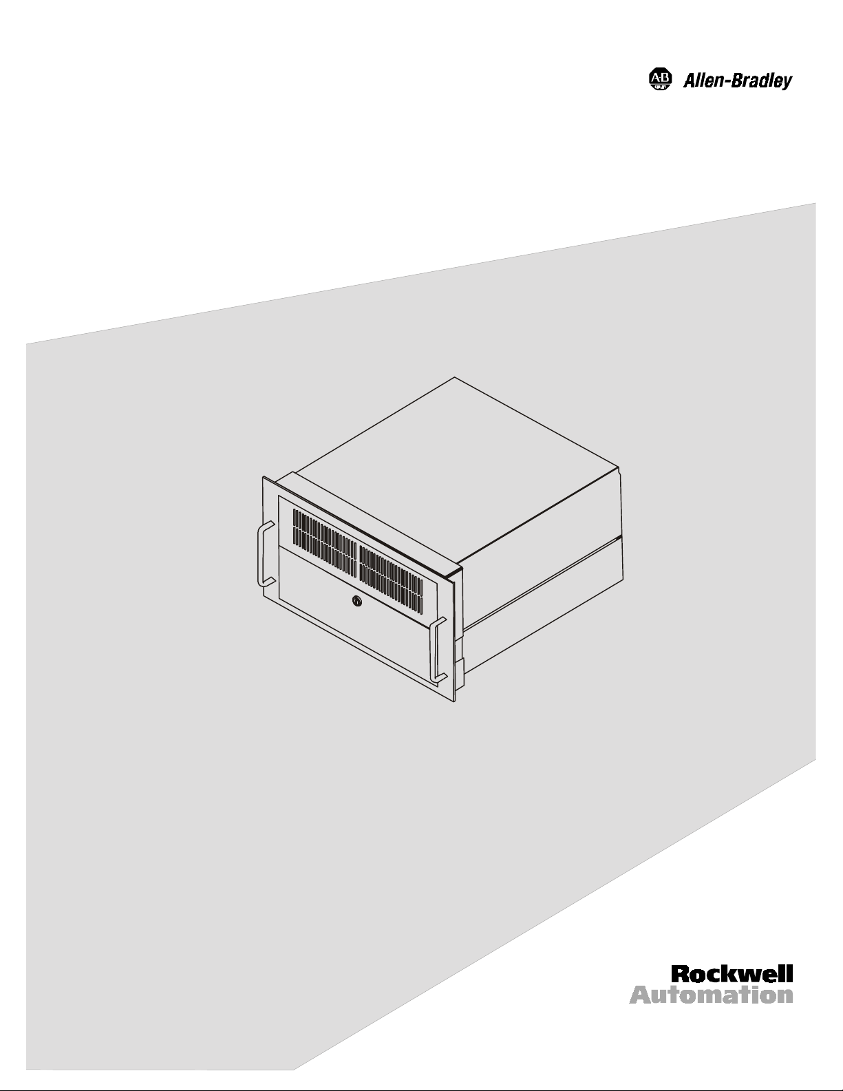
Bulletin 6155 High-Performance
Industrial Computer
Installation Instructions
(Bulleti n 61 55 -x xS )
Page 2

2
Table of Contents
7
7D
DEOH R
EOH RI
Bulletin 6155 High-Performance Industrial Computer
Physical Dimensions............................................................ 5
Installation Instructions........................................................ 5
Replacing Components (Fault Tolerant Models)................... 7
Maintenance......................................................................... 9
Specifications....................................................................... 10
I &RQWH
&RQWHQ
QWV
WV
.... 3
Important User Inf ormation
Solid state equipment has operational characteristics differing from those of
electromechanical equipment. "Safety Guidelines for the Application, Installation, and
Maintenance of Solid State Controls" (Publication SGI-1.1) describes some important
differences between solid state equipment and hard-wired electromechanical devices.
Because of this difference, and because of the wide variety of uses for solid state
equipment, all persons responsible for applying this equipment must satisfy themselves
that each intended application of this equipment is acceptable.
In no event will Rockwell Automation be responsible or liable for indirect or
consequential damages resulting from the use or application of this equipment.
The examples and diagrams in this manual are included solely for illustrative purposes.
Because of the many variables and requirements associated with any particular
installation, Rockwell Automation cannot assume responsibility or liability for actual
use based on the examples and diagrams.
No patent liability is assumed by Rockwell Automation with respect to use of the
informat ion, circuits, equi p m ent, or softwa re described i n t his manu al.
Reproduction of the contents of this manual, in whole or in part, without written
permis si on of Rockwell Automation is p rohibited.
Throughout this manual, we use notes to make you aware of safety considerations.
ATTENTION:
circumstances that can lead to personal injury or death,
property damage, or economic loss.
Important:
application and understanding of the product.
Identifies i n f ormation that is especi al ly important for succes sful
Identifies information about practices or
Publication 6155-UM001A-EN-P
Page 3
Bulletin 6155 Hi gh-Performance Industri al Com puter
%XOOHWLQ
%XOOHWLQ
,QGXVWULDO &RPSX
,QGXVWULDO &RPSXW
+LJK
+LJK
WHU
3
3HU
HU
HUI
IR
RU
UP
PDQFH
DQFH
Description
The Bulletin 6155 High-Performance Industrial Computer provides highperformance computing for specialized or mission-critical applications.
Each 6155-xxS Industrial Computer includes the following common
features:
Pentium III 550 MHz processor
•
•
19 slot passive backplane motherboards (10 full-length PCI
slots, 9 full-l ength ISA slots)
Rack mou nting encl osur e (6U height)
•
3
•
Hot-swappable system cooling fans
CD-ROM and LS120 floppy drive
•
Windows NT Workstation
•
The Bulletin 6155-xxS Industrial Computers can be ordered in
configurations that offer features for more performance and faulttolerance:
Dual Pentium III 550 MHz processors
•
Dual, hot-swappable power supplies
•
Dual, hot-swappable 9+GB SCSI RAID1 hard drives
•
System S entinel monitor and alarm board
•
Windows NT Server
•
Publication 6155-UM001A-EN-P
Page 4

4
Bulletin 6155 Hi gh-Performance Industri al Com puter
Models Covered
Rockwell Automation offers four variations of the Bulletin 6155-xxS
Industrial Computer. The following table describes these models:
Table A
6155-xxS Industrial Computer Models
Catalog Number Description Features
6155-SLSZGMGZGDZ High-
Expandability
6155-SLSZGOGZHDZ
6155-SMSDHMGJGDZ
6155-SMSDHOGJHEZ High pe rfor mance
Fault tolerant with
redundant hard
drive and power
supply
High performance
with dual
processors
fault tolerant
13+ Gbyte hard drive, single Pentium III processor,
4MB video (on-board CPU), 128 MB RAM, single
power supply, Windows NT workstation
9+ Gbyte SCSI RAID1 hard drives, Pentium III
processor, 4MB Video (on-board CPU), 128 MB
RAM, redundant power supply, System Sentinel
monitor and alarm board, Windows NT workstation
13+ Gbyte hard drive, dual Pentium III processors,
8MB PCI video card, 256 MB RAM, single power
supply, Windows NT workstation
9+ Gbyte SCSI RAID1 hard drives, dual Pentium III
processors, 8MB PCI video card, 256 MB RAM,
redundant power supply, System Sentinel moni to r
and alarm board, Windows NT Server
Packin g List
Bulletin 6155-xxS Industrial Computers are shipped with the following
items:
•
Industrial computer
•
Fr ont acces s door keys and drive removal keys for fault tolerant units
•
3.1 m (10ft.) AC power cord
•
Software driver diskettes for major components
•
Co mpo n e nt ma nua ls
•
This manual (Publication 6155-UM001A-EN-P)
Publication 6155-UM001A-EN-P
Page 5

Bulletin 6155 Hi gh-Performance Industri al Com puter
Physical Dime nsi ons
Installation Instructions
Figure 1
Dimensions of 6155-xxS Industrial Computers
5
Note:
Be sure to allow 101-152 mm (4-6 in.) depth clearance for
cable connections and airflow.
Environmental Considerations
For proper c o olin g, the computer requires a minimum fr e e air space of
101-152 mm (4-6 in.) behind, 13-38 mm (0.5-1.5 in.) above, and 2576 mm (1-3 in.) in front of the chassis. The computer is equipped with
fans to help ensure proper coolin g.
ATTENTION:
6155-xxS Industrial Computer, you must ensure that the
cards you install do not result in non-conformance to the
Sa f et y or EMC Requirements for this product .
When you install expansion cards in the
Rack Mounting
The computer can be installed in a rack cabinet that conforms to EIA
standards for equipment with 19-in. wide panels. The cabinet must be
tall enough to accommodate the computer’s height and deep enough to
accommodate the unit’s depth, while providing rear clearance for cabling
and air flow. A cabinet with a depth of 61 cm (24 in.) is sufficient.
Publication 6155-UM001A-EN-P
Page 6

6
Bulletin 6155 Hi gh-Performance Industri al Com puter
The computer is designed to be supported by rack slides or to be placed
on a shelf. The front flanges of the computer are intended to horizontally
secure the unit to the rack cabinet’s front mounting rails.
To install a 6155-xxS Industrial Computer in your rack:
1. Refer to the physical dimension drawings for your unit (Figure 1) to
confirm that there is ade q uate spac e behind the p ane l where the unit
is mounted. Remember to allow extra space for air circulation.
2. Install the rack slides in the rack cabinet.
3. Carefully remove the computer from its packaging.
4. Attach the rack slides to the unit, and align to the mating slide inside
the cabinet.
5. Insert the computer in the rack cabinet from the front of the cabinet.
It will be easier to install the computer if you support it with a
Tip:
shelf or other support adjusted to the appropriate height.
6. Horizontally secure the computer to the front mounting rails of the
rack cab inet.
Connecting AC Power
The computer requires a single-phase power supply providing 85265V AC at 47 to 63 Hz. Power must be available at the three-pin AC
input receptacle situated in the rear of the unit.
To connect AC power to the computer:
1. Use the GND point on the rear panel of the monitor to establish a
chassis to earth ground connection. Secure one end of a ground strap
to the GND point. Connect the other end of the ground strap to a
suit able ea rth ground.
2. Connect the AC power cord provided to the mating connector on the
rear of the computer.
3. Connect the plug end of the AC cord to the main outlet.
Publication 6155-UM001A-EN-P
Install ing Ca bles
Depending on your application, you will need to connect a number of
cables at the rear of the unit before you can properly utilize your
6155-xxS Industrial Computer. This section describes the cable
Page 7

Bulletin 6155 Hi gh-Performance Industri al Com puter
Replacing Components
connections you will need to make. While installing cables, be sure to
keep the following points in mind.
Connect the cables according to the options in your Industrial
•
Computer.
Route and secu re the cables. In cases where the cable cr oss es a d oor
•
hinge, be sure to leave enough excess cable for a loose fit in all door
positions.
Coil and secure any extra cable length in a convenient location.
•
Opening the Computer Chassis
You may have to open th e c omputer cha ssis to inst all a card or for some
oth er rea son.
To open the computer chassis:
1. Loo sen the screws secu ring the co ver to the chassis. There are two
screws on each side and three on the back of the cover (7 screws
total).
7
(Fault Tolerant Models)
2.
Remove the screw on the top cover near the front of the unit.
3.
Raise the top cover by grasping both sides of the cover and
lifting straight up.
With fault-tolerant models of the 6155-xxS Industrial Computer, you
may ne ed to repla ce any of the fo llowi ng components while the
compu ter is in operation:
Table B
Replacement Parts
Part Description
6189-HD90SCSI SCSI disk drive
6189-S5PS1FT Power supply
6189-S5FAN1TACH System cooling fan assembly
Note:
Fault-tolerant models include a System Sentinel monitor
and alarm board that indicates alarm conditions by lighting
LEDs and sounding alarms.
For information on alarm conditions, refer to the System
Sentinel user manual included with your computer.
Publication 6155-UM001A-EN-P
Page 8

8
Bulletin 6155 Hi gh-Performance Industri al Com puter
To replace a SCSI disk drive:
Each SCSI disk dri ve is pla ced in a hard drive ca r rier cartr idge that is
accessible from the front and is equipp ed with a lock. T he lock secu res
the cartridge in place and serves as an ON/OFF switch for the power to
the drive. To repl ace a disk drive, y ou must have th e hard drive carr ier
key to unlock the drive.
Important:
The two SCSI drives in the system are configu re d in a
RAID 1 c onfigura tion. E ach requires a unique drive
identifier.
Before setting a drive in a carrier, the top SCSI drive should
be set to 0 on the 16-positi on swit ch sel e c tor (0-F) . The
bottom SCSI drive should be set to 1.
The dialer-type selector switch is located at the back of the
ca rtridge. To cha nge t he SCSI ID, u se a small flat-head
screwdriver to rotate the a rrow to point to the desired SCSI
ID number.
1. Insert the hard drive carrier key into the lock on the cartridge.
2. Pushing in on the key, turn the key 90 degrees counterclockwise to
unlock the drive.
3. Grasp the handle on the drive ba y and pu ll drive car rier co mplete ly
out of the unit.
4. Pry loose the bottom carrier cover using the supplied tool or a flathead screwdriver.
5. Remove two 6-32 x 3/8” screws from each side of the carrier and
carefully lift the drive out of carrier.
Publication 6155-UM001A-EN-P
6. Remove 3 connectors (power, SCSI, and CRU) from the drive.
7. To install a new drive, reverse the st eps i n this proce d ure.
To replace a power supply:
1. Unplug the AC power cord from the power supply.
2. Remove the middle screw closest to the handle on each side.
3. Grasp the handle and remove the power supply.
4. To install a new power supply, reverse the steps in this procedure.
Page 9

Bulletin 6155 Hi gh-Performance Industri al Com puter
Maintenance
To replace a system cooling fan:
1. Open the front access door and raise the upper door.
2. Determine which fan is no longer functioning.
3. Loosen the thumbscrew securi ng th e fan a s s embl y. Remove the fan
assembly.
4. Disconnect the power cable to the fan assembly.
5. To install a new fan assembly, r everse the steps in this procedure.
Preparation for Shipment
If it is necessary to ship the computer from one site to another, it should
be removed from the rack cabinet in which it has been installed.
Whenever possible, the computer should be repac ked i n its original
shipping cart on.
9
ATTENTION:
while it is mounted in a ra c k. Doing so coul d result in
damage to the rack or the Indu str ial Co mputer.
To remove the computer from the rack cabinet, reverse the installation
procedures given previously in this manual.
Note:
Be careful to remove the ground wire (if installed) before
removing the computer from the rack cabinet.
Never try to ship the Industrial Computer
Cleaning
Filters s hould be remo ved and c lean e d or r ep l aced as neces sar y to
maintain proper cooling (replacement part 6189-S5FILTER). Inspect the
filter at least yearly, a nd more often in environments with large
concentrations of airborne particulate matter.
Publication 6155-UM001A-EN-P
Page 10

10
Specific ations
Bulletin 6155 Hi gh-Performance Industri al Com puter
Processor/Memory
Processor/Speed (MHz) Pentium III 550Mhz or Dual Pentium III 550 MHz
Memory Options 128M (6155-SLS Models)
256M (6155-SMS Models)
System
System Bus Architecture 32-bit PCI/ 16-bit ISA, 20-slot passive backplane)
Expansion Slots 19 full length slots (10 PCI, 9 ISA)
Serial Ports, Standard 2
Parallel Ports, Standard 1
USB Ports 2
Operating Systems Windows NT Workstation
Windows N T Server (S M M od el onl y)
Network Support 10/100 PCI Ethernet Card
Mass Storage
Internal Drive Bays 5 (rack mount/benchtop):
2 3.5” hard dri v e m oun t i ng l oc ations
2 5.25 ” device bays
1 3.5” device bay
Diskette Drive LS-120 super drive (supports 3.5" 1.44MB floppy
Hard Disk drives 13+ Gbyte HDD or 9 Gbyte SCSI (RAID1)
Operator Input
Standar d Keyboard Interface Rear pan el PS / 2 c onn ec tor
Video C ontr oller (for ext er n al
monitor)
disks and 120MB LS-120 disks)
Single processor: ATI Rage Pro AGP on board
Dual processor: AT I X p ert SVGA card with 8 MB
VRAM
Publication 6155-UM001A-EN-P
Page 11

Bulletin 6155 Hi gh-Performance Industri al Com puter
Environmental
Temperature
Operating
Non-operating
Relati ve Hu midity 5% to 90% non-condensing
Vibrati on
Operating
Non-operating
Shock
Operating
Non-operating
Electrical
Line volt ag e 85-265V A C
Line Frequ ency 47-63 Hz
Power Consumption 200W typical, 400W max.
Physical
Approximate Dimensions
(W x H x D)
Net Weight
0 C to 50°C
-25°C to 70°C
0.006in. p-p, 10-57Hz sine; 1.0g peak, 57-150Hz sine
0.012in. p-p, 10-57Hz sine, 2.0g peak, 57-150Hz sine
15g (1/2 sine, 11 msec)
30g (1/2 sine, 11 msec)
19.0in x 10. 5in x 19.0in
(483mm x 267mm x 483mm)
40 lb. (18 kg) (6155-SLS Models)
58 lb. (23 kg) (6155-SMS Models)
11
Agency Appr o v al
LVD
(73/23/E EC )
EMC
(89/336/EEC)
UL 1950 Recognized Component,
C-UL 950 R ec og ni z ed C om p on ent
EN 60950 (A1: 1992, A2:1993)
EN 50081-2: 1992
EN 50082-2: 1995
Publication 6155-UM001A-EN-P
Page 12

IBM is a registered trademar k of In ternational Business Machines Cor poration.
VGA is a trademar k of International Business Mach ines Corporation.
PC AT is a tradem ark of International Business Machines Corporat ion.
Microsoft is a registered trademark of Microsoft Corporation.
Microsoft Windows is a tr ademark of Microsoft Corpor ati on.
System Sentinel is a tradem ark of I-Bus/Phoenix Corporation.
Rockwell Automation helps its customers receiv e a superior retu rn on their inv est ment by bringing
together leading brands in i ndustrial automation, creating a broad spectrum of easy-to-integrate
products. T hese are supported by local technical resources availabl e worldwide, a gl obal network of
system s olutions provid ers, and the advanced technology resourc es of Rockwell.
Worldwide representation.
Argentina • Australia • Austria • Bahrain • Belgium • Bolivia • Brazil • Bulgaria • Canada • Chile • China, People’s Republic of • Colombia • Costa Rica • Croatia • Cyprus • Czech
Republic • Denmark • Dominican Republic • Ecuador • Egypt • El Salvador • Finland • France • Germany • Ghana • Greece • Guatemala • Honduras • Hong Kong • Hungary
Iceland • India • Indonesia • Iran • Ireland • Israel • Italy • Jamaica • Japan • Jordan • Korea • Kuwait • Lebanon • Macau • Malaysia • Malta • Mexico • Morocco • The Netherlands
New Zealand • Nigeria • Norway • Oman • Pakistan • Panama • Peru • Philippines • Poland • Portugal • Puerto Rico • Qatar • Romania • Russia • Saudi Arabia • Singapore
Slovakia • Slovenia • South Africa, Republic of • Spain • Sweden • Switzerland • Taiwan • Thailand • Trinidad • Tunisia • Turkey • United Arab Emirates • United Kingdom • United
States • Uruguay • Venezuela
Rockwell Automation Headquarters, 1201 South Second Street, Milwaukee, WI 53204-2496 USA, Tel: (1) 414 382-2000, Fax: (1) 414 382-4444
Rockwell Automation European Headquarters, Avenue Hermann Debroux, 46 1160 Brussels, Belgium, Tel: (32) 2 663 06 00, Fax: (32) 2 663 06 40
Rockwell Automation Asia Pacific Headquarters, 27/F Citicorp Centre, 18 Whitfield Road, Causeway Bay, Hong Kong, Tel: (852) 2887 4788, Fax: (852) 2508 1846
World Wide Web: http://www.ab.com
998080-010
Publication 6155-UM001A-EN-P
Copyright 2000 Rockwell Automation Corporation. All rights reserved. Printed in USA.
•
•
•
 Loading...