

Page 1
Installation Instructions
PHOTOcountSWITCHt Totalizer Series 5000 Accessories
Adds ability to count without losing photoelectric countrol function switching capability
IMPORTANT: SAVE THESE INSTRUCTIONS FOR FUTURE USE.
Refer to the product catalog pages for additional information.
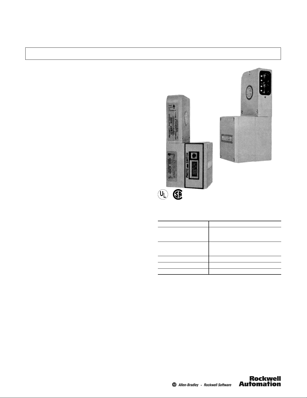
Description
The #60--2072 PHOTOcountSWITCH Totalizer counter can
be added to any Series 5000 QD Green Line photoelectric
sensor to provide sensing and control plus counting in one
economical easy-to-use package. Addition of this counting
module does not in any way impair the switching capability of
the Series 5000 photoelectric sensor. Nor does it require any
additional wiring or external power supplies to make it
operate.
The #60--2072 Totalizer counter is simply inserted between
any Type 42MTB Terminal Base (except model 5004) and its
cover. No additional wiring is required. The cover is
remounted using the four (4) longer mounting screws
supplied with the Totalizer.
It should be noted that the #60--2072 Totalizer has two pins,
which connect through matching holes in the output module,
to provide the signal to the counter. The #60--2072 Totalizer
can be used with any output module, #8--590 E--M Relay
(with date codes 8509 or later); #8--591 F.E.T. or #8--592 Triac
(with date codes 8622 or later).
The #60--2072 Totalizer has a six-digit LCD display, 5 mm
(0.2 in.) high. It contains a custom monolithic counter/drive
chip that performs all the counting functions.
The count display and memory are powered by an easily
replaceable 3V DC Lithium battery which prevents loss of
counts due to a power failure. The battery which is supplied
with the totalizer has an average expected life greater than
five years.
An external manual reset button, located next to the display,
can be depressed to reset the counter to zero. The Totalizer
also includes an internal switch which disables the manual
reset function to prevent accidental or unauthorized resetting
of the counter.
The Totalizer count signal is obtained directly from the output
circuit of the photoelectric sensor. This permits the use of the
sensor to perform normal switching functions in addition to
counting.
The Series 5000 is installed and aligned as described in the
bulletin supplied with each sensor. The #60--2072 Totalizer is
designed to maintain the NEMA 3, 4, 5, 12 and 13
environmental rating of the sensor.
Features
S Easily added in the field to any Green Line Series 5000
photoelectric sensor without additional wiring
S Reliable high-speed counting
S Six-digit LCD display, 5 mm (2 in.) high—easily readable
S No loss of count when power fails
S Counter powered by replaceable 3V DC Lithium
battery—battery life expectancy more than five years
S External manual reset
S Internal reset disable switch—prevents unauthorized
resets
S NEMA 3, 4, 5, 12 and 13 rated
S UL Listed and CSA Certified
®
®
Specifications
Display Six-digit LCD, 5 mm (0.2 in.) high
Memory Display Power:
Count Speed
with 42MRU photohead
with 42MRP photothead
Operating Temperature [C (F)] 0…50° (32…122°)
Storage Temperature [C (F)] -- 2 0 …60° (--4…140°)
Relative Humidity
A slot is provided in the back of the housing to assist in removal of battery.
The counter display fails to operate in 85% Relative Humidity at 50°C
(122°F). The failure mode is a blank display.
Supply
Battery Life
Series 5000 Sensor
with #60--2072
PHOTOcountSWITCH
Totalizer
3V DC Lithium battery (replaceable)
5 years, minimum
(25% minimum duty cycle)
200 cps
70 cps
1
Page 2
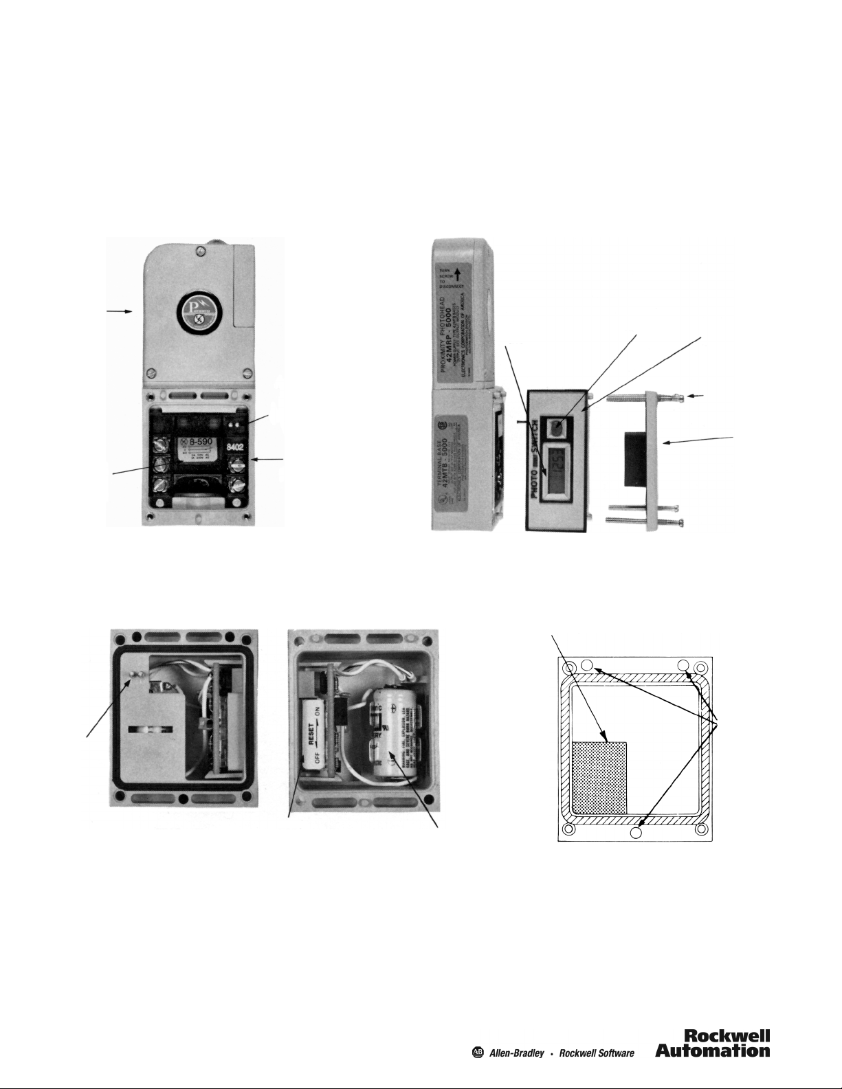
Installation
1. Remove the cover from the 42MTB Terminal Base
(Figures 1 and 2).
2. Remove four (4) screws from cov er.
3. Install output module into terminal base . Note location
of the two holes for the Totalizer contact pins (Figure 1).
4. Mount #60--2072 Totalizer onto the 42MTB Terminal
Base so that the contacting pins fit into the two holes in
the output module (Figures 2 and 3).
5. Set the internal reset disable switch in the desired position
(Figure 3).
6. Remove backing paper from vibration pad (supplied) and
apply to the side of the cover as shown in Figure 4.
7. Replace the cover using the longer (4) screws
supplied with the #60--2072 Totalizer.
42MR
Photohead
Output
module
Two holes for
contact pins
42MTB
terminal
base
Six-digit display
External
Reset
#60--2072
Totalizer
(four) cover
screws
Figure 1: Photoelectric sensor assembly Figure 2: #60--2072 PHOTOcountSWITCH assembly
Locate vibration pad on inside of cover as shown
(Top)
42MTB
cover
Cover
locating
Contact
pins
(Rear View)
Reset disable
switch
(Front View)
Lithium
battery
holes
Figure 3: #60--2072 PHOTOcountSWITCH Totalizer Figure 4: Vibration pad installation
2
Page 3

Approximate Dimensions [mm (in.)]
Quick-disconnect screw
36.5
(1 7/16)
To remove scanner
2.7
(7/64)
8.7
(11/32) min.
71.0
(2 51/64)
LED Indicator
24.2
(61/64)
19.4
(49/64)
11.9 (15/32)
36.5
(1 7/16)
15.4
(39/64)
54.7
(2 5/32)
54.7 (2 5/32)
65.8
(2 19/32)
Display opposite
side
27.3
(1 5/64)
1/2--14
NPSM
62.3 (2 29/64)
13.8
(35/64)
(4 1/4)
38.1
(1 1/2)
8.3
(21/64)
106.5
139.5
(5 33/64)
Note: For bracket dimensions refer to control bulletin.
10--32 UNF 2 holes
3
Page 4

PA--8601 -- January 1987 (B)
Supersedes August 1986 (A)
4
 Loading...