

Page 1

AllenBradley
VMEbus
Remote I/O
User
Scanner
(Cat.
No. 6008SV1R,
6008SV2R)
Manual
Page 2
Important User Information
Because of the variety of uses for the products described in this
publication, those responsible for the application and use of this control
equipment must satisfy themselves that all necessary steps have been taken
to assure that each application and use meets all performance and safety
requirements, including any applicable laws, regulations, codes and
standards.
The illustrations, charts, sample programs and layout examples shown in
this guide are intended solely for purposes of example. Since there are
many variables and requirements associated with any particular
installation, Allen-Bradley does not assume responsibility or liability
(to include intellectual property liability) for actual use based upon the
examples shown in this publication.
Allen-Bradley publication SGI-1.1, Safety Guidelines for the Application,
Installation, and Maintenance of Solid State Control (available from your
local Allen-Bradley office), describes some important differences between
solid-state equipment and electromechanical devices that should be taken
into consideration when applying products such as those described in this
publication.
Reproduction of the contents of this copyrighted publication, in whole or
in part, without written permission of Allen-Bradley Company, Inc., is
prohibited.
Throughout this manual we use notes to make you aware of safety
considerations:
ATTENTION: This notation identifies information about
practices or circumstances that can lead to personal injury or
death, property damage or economic loss.
Attention statements help you to:
identify a hazard
avoid the hazard
recognize the consequences
Important: This notation identifies information that is critical for
successful application and understanding of the product.
Page 3

Table of Contents
Using This Manual pi. . . . . . . . . . . . . . . . . . . . . . . . . . . . . . .
Introduction pi. . . . . . . . . . . . . . . . . . . . . . . . . . . . . . . . . . . . . . . .
Audience pi
Required Hardware pi
Terms
Scanner Overview 11. . . . . . . . . . . . . . . . . . . . . . . . . . . . . . .
Using This Chapter 11. . . . . . . . . . . . . . . . . . . . . . . . . . . . . . . . . .
Introduction 11
VMEbus
How the Scanner Scans 16
Comparison to 6008SV Scanner 18
Operating Modes 19
VME Master Processor Watchdog Timer 111
. . . . . . . . . . . . . . . . . . . . . . . . . . . . . . . . . . . . . . . . . .
. . . . . . . . . . . . . . . . . . . . . . . . . . . . . . . . . .
. . . . . . . . . . . . . . . . . . . . . . . . . . . . . . . . . . . . . . . . . . . .
. . . . . . . . . . . . . . . . . . . . . . . . . . . . . . . . . . . . . . . .
Relationship
. . . . . . . . . . . . . . . . . . . . . . . . . . . . . . .
. . . . . . . . . . . . . . . . . . . . . . . .
. . . . . . . . . . . . . . . . . . . . . . . . . . . . . . . . . . . .
. . . . . . . . . . . . . . . . . . .
pii
14. . . . . . . . . . . . . . . . . . . . . . . . . . . . . . . . .
Installing the Scanner 21. . . . . . . . . . . . . . . . . . . . . . . . . . . .
Using This Chapter 21. . . . . . . . . . . . . . . . . . . . . . . . . . . . . . . . . .
Handling the Scanner 21
Setting Switches 21
Removing VME Backplane Jumpers 26
Grounding the VME Chassis 26
Inserting the Scanner 27
Determining PowerSupply Requirements 27
Connecting
Addressing
Using This Chapter 31. . . . . . . . . . . . . . . . . . . . . . . . . . . . . . . . . .
I/O Addressing Concept 31
Choosing an Addressing Mode 33
Addressing BlockTransfer Modules 36
Assigning Racks 37
to the Remote I/O Link
I/O
. . . . . . . . . . . . . . . . . . . . . . . . . . . . . . . . .
. . . . . . . . . . . . . . . . . . . . . . . . . . . . . . . . . . . .
. . . . . . . . . . . . . . . . . . . . . .
. . . . . . . . . . . . . . . . . . . . . . . . . . . .
. . . . . . . . . . . . . . . . . . . . . . . . . . . . . . . . .
. . . . . . . . . . . . . . . . . .
28. . . . . . . . . . . . . . . . . . . . . . . .
31. . . . . . . . . . . . . . . . . . . . . . . . . . . . . . . . . .
. . . . . . . . . . . . . . . . . . . . . . . . . . . . . . .
. . . . . . . . . . . . . . . . . . . . . . . . . .
. . . . . . . . . . . . . . . . . . . . . .
. . . . . . . . . . . . . . . . . . . . . . . . . . . . . . . . . . . .
Communicating with Remote I/O 41. . . . . . . . . . . . . . . . . . . .
Using This Chapter 41. . . . . . . . . . . . . . . . . . . . . . . . . . . . . . . . . .
Selecting Devices that You Can Connect 41
Introduction
Designing
Specifying a Scan List 45
Processing
Processing Block Data 48
to Remote I/O
a Remote I/O Link
. . . . . . . . . . . . . . . . . . . . . . . . . . . . . . . .
Discrete I/O
. . . . . . . . . . . . . . . . . . . . . . . . . . . . . . . .
. . . . . . . . . . . . . . . . . . .
42. . . . . . . . . . . . . . . . . . . . . . . . . . . . .
43. . . . . . . . . . . . . . . . . . . . . . . . . . . .
46. . . . . . . . . . . . . . . . . . . . . . . . . . . . . . .
Page 4

Table of Contentsii
Operating
Using This Chapter 51. . . . . . . . . . . . . . . . . . . . . . . . . . . . . . . . . .
Addressing
Command Summary 56
SETUP command byte 13 57
description 57
parameters 58
coding sequence 58
AUTOCONFIGURE command byte 10 59
description 59
parameters 510
coding sequence 512
SCAN LIST command byte 11 513
description 513
parameters 513
coding sequence 515
FAULT DEPENDENT GROUP command byte 12 516
description 516
parameters 516
coding sequence 518
SET MODE command byte 20 519
description 519
parameters 519
coding sequence 520
LINK STATUS command byte 21 521
description 521
parameters 522
coding sequence 524
BT READ command byte 01 525
description 525
parameters 526
coding sequence 526
BT WRITE command byte 02 527
description 527
parameters 527
coding sequence 528
RESET 529
description 529
parameters 530
coding sequence 530
in SV
Compatible Mode 51. . . . . . . . . . . . . . . . . . .
Global RAM
. . . . . . . . . . . . . . . . . . . . . . . . . . . . . . . . .
. . . . . . . . . . . . . . . . . . . . . . . . . . . . . .
. . . . . . . . . . . . . . . . . . . . . . . . . . . . . . . . . . . . . . . .
. . . . . . . . . . . . . . . . . . . . . . . . . . . . . . . . . . . . . . . .
. . . . . . . . . . . . . . . . . . . . . . . . . . . . . . . . . . . .
. . . . . . . . . . . . . . . . . . . . .
. . . . . . . . . . . . . . . . . . . . . . . . . . . . . . . . . . . . . . . .
. . . . . . . . . . . . . . . . . . . . . . . . . . . . . . . . . . . . . . . .
. . . . . . . . . . . . . . . . . . . . . . . . . . . . . . . . . . . .
. . . . . . . . . . . . . . . . . . . . . . . . . . .
. . . . . . . . . . . . . . . . . . . . . . . . . . . . . . . . . . . . . . . .
. . . . . . . . . . . . . . . . . . . . . . . . . . . . . . . . . . . . . . . .
. . . . . . . . . . . . . . . . . . . . . . . . . . . . . . . . . . . .
. . . . . . . . . . . . .
. . . . . . . . . . . . . . . . . . . . . . . . . . . . . . . . . . . . . . . .
. . . . . . . . . . . . . . . . . . . . . . . . . . . . . . . . . . . . . . . .
. . . . . . . . . . . . . . . . . . . . . . . . . . . . . . . . . . . .
. . . . . . . . . . . . . . . . . . . . . . . . . . .
. . . . . . . . . . . . . . . . . . . . . . . . . . . . . . . . . . . . . . . .
. . . . . . . . . . . . . . . . . . . . . . . . . . . . . . . . . . . . . . . .
. . . . . . . . . . . . . . . . . . . . . . . . . . . . . . . . . . . .
. . . . . . . . . . . . . . . . . . . . . . . . .
. . . . . . . . . . . . . . . . . . . . . . . . . . . . . . . . . . . . . . . .
. . . . . . . . . . . . . . . . . . . . . . . . . . . . . . . . . . . . . . . .
. . . . . . . . . . . . . . . . . . . . . . . . . . . . . . . . . . . .
. . . . . . . . . . . . . . . . . . . . . . . . . . . .
. . . . . . . . . . . . . . . . . . . . . . . . . . . . . . . . . . . . . . . .
. . . . . . . . . . . . . . . . . . . . . . . . . . . . . . . . . . . . . . . .
. . . . . . . . . . . . . . . . . . . . . . . . . . . . . . . . . . . .
. . . . . . . . . . . . . . . . . . . . . . . . . . .
. . . . . . . . . . . . . . . . . . . . . . . . . . . . . . . . . . . . . . . .
. . . . . . . . . . . . . . . . . . . . . . . . . . . . . . . . . . . . . . . .
. . . . . . . . . . . . . . . . . . . . . . . . . . . . . . . . . . . .
. . . . . . . . . . . . . . . . . . . . . . . . . . . . . . . . . . . . . . . . . . .
. . . . . . . . . . . . . . . . . . . . . . . . . . . . . . . . . . . . . . . .
. . . . . . . . . . . . . . . . . . . . . . . . . . . . . . . . . . . . . . . .
. . . . . . . . . . . . . . . . . . . . . . . . . . . . . . . . . . . .
51. . . . . . . . . . . . . . . . . . . . . . . . . . . . . . .
Page 5

Table of Contents iii
Operating
Using This Chapter 61. . . . . . . . . . . . . . . . . . . . . . . . . . . . . . . . . .
Addressing
Command Summary 67
SETUP command byte 13 68
description 68
parameters 68
coding sequence 610
AUTOCONFIGURE command byte 10 611
description 611
parameters 612
coding sequence 614
SCAN LIST command byte 11 615
description 615
parameters 615
coding sequence 617
FAULT DEPENDENT GROUP command byte 12 618
description 618
parameters 618
coding sequence 620
SET MODE command byte 20 621
description 621
parameters 621
coding sequence 622
LINK STATUS command byte 21 623
description 623
parameters 624
coding sequence 627
BT READ command byte 01 628
description 628
parameters 630
coding sequence 631
BT WRITE command byte 02 632
description 632
parameters 634
coding sequence 635
CONTINUOUS BT READ command byte 06 636
description 636
parameters 638
coding sequence 639
CONTINUOUS BT WRITE command byte 07 640
description 640
parameters 642
coding sequence 643
RESET 644
in SV
Superset Mode 61. . . . . . . . . . . . . . . . . . . . .
Global RAM
. . . . . . . . . . . . . . . . . . . . . . . . . . . . . . . . .
. . . . . . . . . . . . . . . . . . . . . . . . . . . . . .
. . . . . . . . . . . . . . . . . . . . . . . . . . . . . . . . . . . . . . . .
. . . . . . . . . . . . . . . . . . . . . . . . . . . . . . . . . . . . . . . .
. . . . . . . . . . . . . . . . . . . . . . . . . . . . . . . . . . . .
. . . . . . . . . . . . . . . . . . . . .
. . . . . . . . . . . . . . . . . . . . . . . . . . . . . . . . . . . . . . . .
. . . . . . . . . . . . . . . . . . . . . . . . . . . . . . . . . . . . . . . .
. . . . . . . . . . . . . . . . . . . . . . . . . . . . . . . . . . . .
. . . . . . . . . . . . . . . . . . . . . . . . . . .
. . . . . . . . . . . . . . . . . . . . . . . . . . . . . . . . . . . . . . . .
. . . . . . . . . . . . . . . . . . . . . . . . . . . . . . . . . . . . . . . .
. . . . . . . . . . . . . . . . . . . . . . . . . . . . . . . . . . . .
. . . . . . . . . . . . .
. . . . . . . . . . . . . . . . . . . . . . . . . . . . . . . . . . . . . . . .
. . . . . . . . . . . . . . . . . . . . . . . . . . . . . . . . . . . . . . . .
. . . . . . . . . . . . . . . . . . . . . . . . . . . . . . . . . . . .
. . . . . . . . . . . . . . . . . . . . . . . . . . .
. . . . . . . . . . . . . . . . . . . . . . . . . . . . . . . . . . . . . . . .
. . . . . . . . . . . . . . . . . . . . . . . . . . . . . . . . . . . . . . . .
. . . . . . . . . . . . . . . . . . . . . . . . . . . . . . . . . . . .
. . . . . . . . . . . . . . . . . . . . . . . . .
. . . . . . . . . . . . . . . . . . . . . . . . . . . . . . . . . . . . . . . .
. . . . . . . . . . . . . . . . . . . . . . . . . . . . . . . . . . . . . . . .
. . . . . . . . . . . . . . . . . . . . . . . . . . . . . . . . . . . .
. . . . . . . . . . . . . . . . . . . . . . . . . . . .
. . . . . . . . . . . . . . . . . . . . . . . . . . . . . . . . . . . . . . . .
. . . . . . . . . . . . . . . . . . . . . . . . . . . . . . . . . . . . . . . .
. . . . . . . . . . . . . . . . . . . . . . . . . . . . . . . . . . . .
. . . . . . . . . . . . . . . . . . . . . . . . . . .
. . . . . . . . . . . . . . . . . . . . . . . . . . . . . . . . . . . . . . . .
. . . . . . . . . . . . . . . . . . . . . . . . . . . . . . . . . . . . . . . .
. . . . . . . . . . . . . . . . . . . . . . . . . . . . . . . . . . . .
. . . . . . . . . . . . . . . . .
. . . . . . . . . . . . . . . . . . . . . . . . . . . . . . . . . . . . . . . .
. . . . . . . . . . . . . . . . . . . . . . . . . . . . . . . . . . . . . . . .
. . . . . . . . . . . . . . . . . . . . . . . . . . . . . . . . . . . .
. . . . . . . . . . . . . . . .
. . . . . . . . . . . . . . . . . . . . . . . . . . . . . . . . . . . . . . . .
. . . . . . . . . . . . . . . . . . . . . . . . . . . . . . . . . . . . . . . .
. . . . . . . . . . . . . . . . . . . . . . . . . . . . . . . . . . . .
. . . . . . . . . . . . . . . . . . . . . . . . . . . . . . . . . . . . . . . . . . .
61. . . . . . . . . . . . . . . . . . . . . . . . . . . . . . .
Page 6

Table of Contentsiv
description 644. . . . . . . . . . . . . . . . . . . . . . . . . . . . . . . . . . . . . . . .
parameters 645
coding sequence 645
. . . . . . . . . . . . . . . . . . . . . . . . . . . . . . . . . . . . . . . .
. . . . . . . . . . . . . . . . . . . . . . . . . . . . . . . . . . . .
Starting the Scanner 71. . . . . . . . . . . . . . . . . . . . . . . . . . . . .
Using This Chapter 71. . . . . . . . . . . . . . . . . . . . . . . . . . . . . . . . . .
Understanding the Scanner States 71
Powering Up the Scanner 74
After Waking Up the Scanner 78
. . . . . . . . . . . . . . . . . . . . . . . . . . . . . .
. . . . . . . . . . . . . . . . . . . . . . .
. . . . . . . . . . . . . . . . . . . . . . . . . . .
Programming the Scanner 81. . . . . . . . . . . . . . . . . . . . . . . . .
Using This Chapter 81. . . . . . . . . . . . . . . . . . . . . . . . . . . . . . . . . .
Using the Semaphore 81
Knowing When a Command Is Complete 82
Programming Examples of Each Scanner Management Command 82
Programming Block Transfers 834
Communicating with PLC5 Processor in Adapter Mode 839
. . . . . . . . . . . . . . . . . . . . . . . . . . . . . . . . .
. . . . . . . . . . . . . . . . . . .
.
. . . . . . . . . . . . . . . . . . . . . . . . . . .
. . . . . . . .
Troubleshooting 91. . . . . . . . . . . . . . . . . . . . . . . . . . . . . . . .
Using This Chapter 91. . . . . . . . . . . . . . . . . . . . . . . . . . . . . . . . . .
Indicators 91
Error Codes 92
Troubleshooting Suggestions 94
. . . . . . . . . . . . . . . . . . . . . . . . . . . . . . . . . . . . . . . . .
. . . . . . . . . . . . . . . . . . . . . . . . . . . . . . . . . . . . . . . .
. . . . . . . . . . . . . . . . . . . . . . . . . . .
Specifications A1. . . . . . . . . . . . . . . . . . . . . . . . . . . . . . . . . .
Environmental
Performance
VMEbus
Specifications
Specifications
Specifications
A1. . . . . . . . . . . . . . . . . . . . . . . . . . .
A1. . . . . . . . . . . . . . . . . . . . . . . . . . . . .
A2. . . . . . . . . . . . . . . . . . . . . . . . . . . . . . . .
Page 7

Using This Manual
Preface
Introduction
Audience
Required Hardware
This manual describes how to install and use the VMEbus remote I/O
scanners (catalog numbers 6008-SV1R and 6008-SV2R).
You should have experience in system development and integration and in
writing software for VMEbus master processors. You should also have a
working knowledge of the C programming language, including the concepts
of structures and pointers. Knowledge of Allen-Bradley 1771 I/O products
is helpful but not essential.
You need a VMEbus-compatible VME master processor to set up and
control the VMEbus remote I/O scanner. You install the scanner in a
standard 6U, full-height VME rack.
The 1771 I/O modules that the scanner monitors and controls depend on
your application. You also need an adapter in the 1771 chassis to allow
communication between the scanner and the I/O modules. You can use any
A-B adapter module or a PLC-5 processor that operates in adapter mode.
pi
Page 8

Preface
Terms
This table defines common terms:
This term: Refers to the:
scanner
VME master processor main CPU of your VME system
VME chassis frame that VME cards are mounted in
VMEbus circuit board or backplane mounted in the chassis that the scanner, the
I/O chassis AllenBradley 1771 series I/O chassis
input image table area of global memory in the scanner that contains the data from the
output image table area of global memory in the scanner that contains output data for
block transfer transfer of data between an intelligent I/O module and a scanner
general data area designated area of global VME memory, existing within the scanner,
global RAM an area of global VME memory in the scanner that can be accessed
semaphore bit bit that indicates whether part of the global RAM (the general data
scan list list that the scanner maintains internally to determine the I/O racks that
both remote scanners (catalog numbers 6008SV1R and 6008SV2R)
The VME master processor runs the application program that
accesses the scanner. A VME system can have more than one VME
master processor, each assigned different duties and both accessing
the same scanner(s).
Both the scanner and the VME master processor are mounted in the
chassis along with other VME hardware.
VME master processor, and other VME cards plug into
This is the frame that houses the I/O modules, power supply, and
adapter or PLC processor.
input terminals of input modules
When an input switch is closed its corresponding input bit in the image
table is set to 1.
terminals of output modules
When a bit is set to 1, the corresponding output turns on.
A block transfer sends as many as 64 words of data at a time.
that is used to pass information between the scanner and a VME
master processor.
Scanner commands are processed in this data area.
by both the scanner and the VME master processor(s).
This area of memory is the key means for communication between the
scanner and the VME master
area) is being used.
Typically this bit is used to prevent multiple masters or the scanner
from writing to the general data area simultaneously.
it is to scan, and the order in which it is to scan them.
You create the scan list using the AUTOCONFIGURE command or the
SCAN LIST command.
pii
Page 9

Scanner Overview
Chapter
1
Using This Chapter
Introduction
This chapter provides an overview of the scanner. This chapter describes
how the scanner relates to the VMEbus and to the remote I/O link.
If you want to read about: go to page:
introduction
VMEbus relationship 14
how the scanner scans 16
operating modes 19
VME master processor watchdog timer 111
The VMEbus scanners (catalog number 6008-SV1R and 6008-SV2R)
monitor and control remote Allen-Bradley I/O modules without using a
PLC processor. Use your VME master processor(s) to manage as many as
32 racks of remote A-B I/O (16 per scanner channel).
The scanner communicates with I/O adapters that reside in the left slot of a
remote chassis and with other products that have node adapters built into
them. The scanner transfers the information necessary to control discrete
and block-transfer data to and from the VMEbus.
The VMEbus scanner physically resides in the VME chassis. The scanner
occupies one 6U (full-height) VME slot. The scanner uses the P1
connector to interface to the VMEbus. You can use more than one scanner
in your VME system to create large and flexible I/O subsystems.
11
To the VMEbus, the scanner is a memory-mapped slave that responds to
8-bit or 16-bit accesses in either A16 or A24 address space. The scanner
can act as a VME interrupter on any of the seven VMEbus interrupt lines.
The SV1R and SV2R scanners replace the Allen-Bradley 6008-SV
scanner. The SV1R has one remote I/O channel; the SV2R has two remote
I/O channels. The SV1R and SV2R scanners have an extra embedded
communication microprocessor, which gives them more flexibility and
faster performance than the 6008-SV scanner. The new scanners are
backward-compatible with the 6008-SV scanner and offer:
continuous block-transfer operations
each remote I/O channel supports as many as 16 racks of remote I/O
configurable scan rate at 57.6, 115.2, or 230.4 kbps
VME interrupt signals change in the scanner input table
11
Page 10
Chapter
1
Scanner Overview
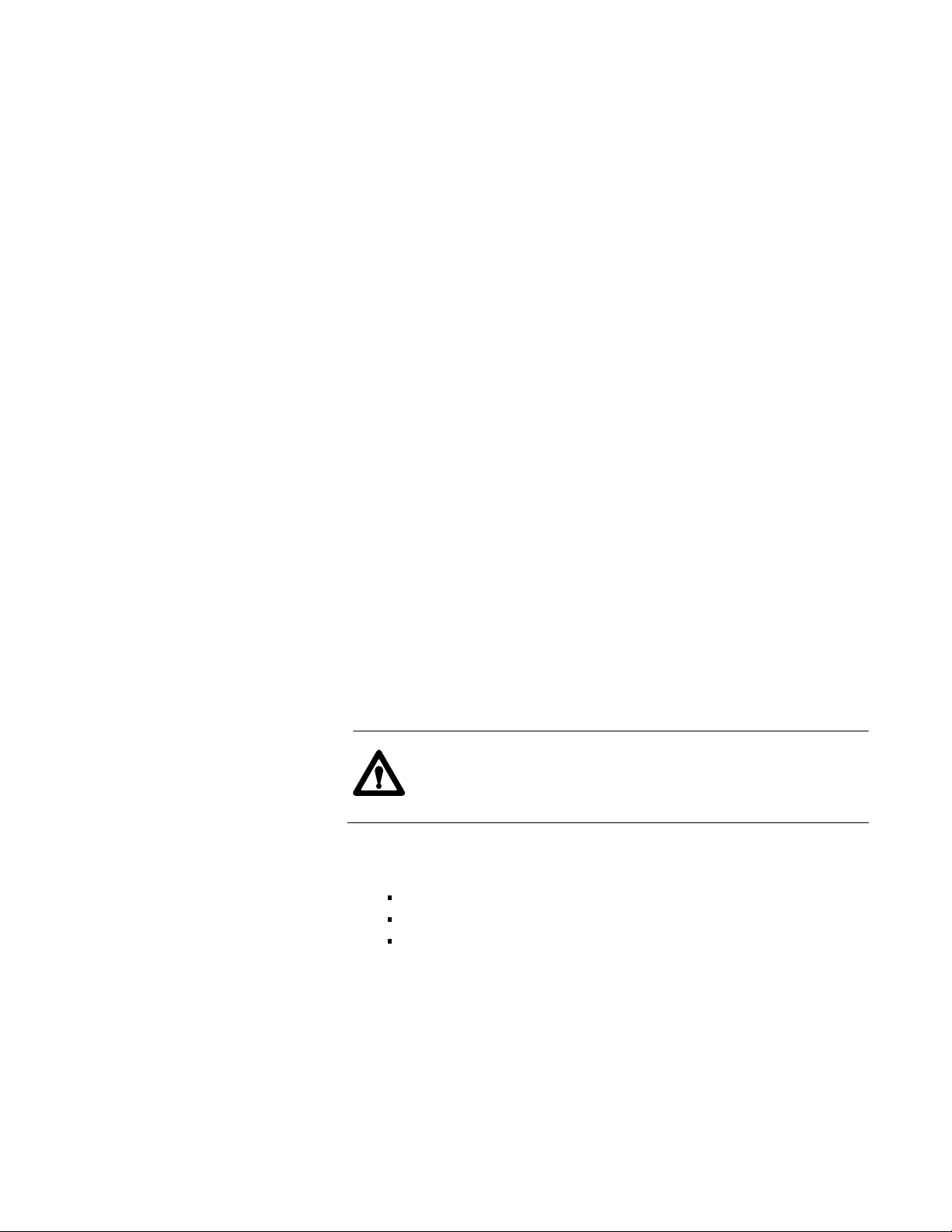
Figure 1.1
connection overview
System
HP 9000 computer
VAX computer
Ethernet network
Vision
VME CPU
VME CPU
PanelView
PLC5 processor
Ethernet
Data
remote I/O
channel B
6008SV2R
VME chassis
remote I/O
channel A
1336 drive
Flex I/O
Note: The 6008SV1R scanner is interchangeable with the 6008SV2R scanner,
except that the SV1R scanner supports only one channel of remote I/O.
12
chassis with 1771ASB
Page 11
Chapter
1
Scanner Overview
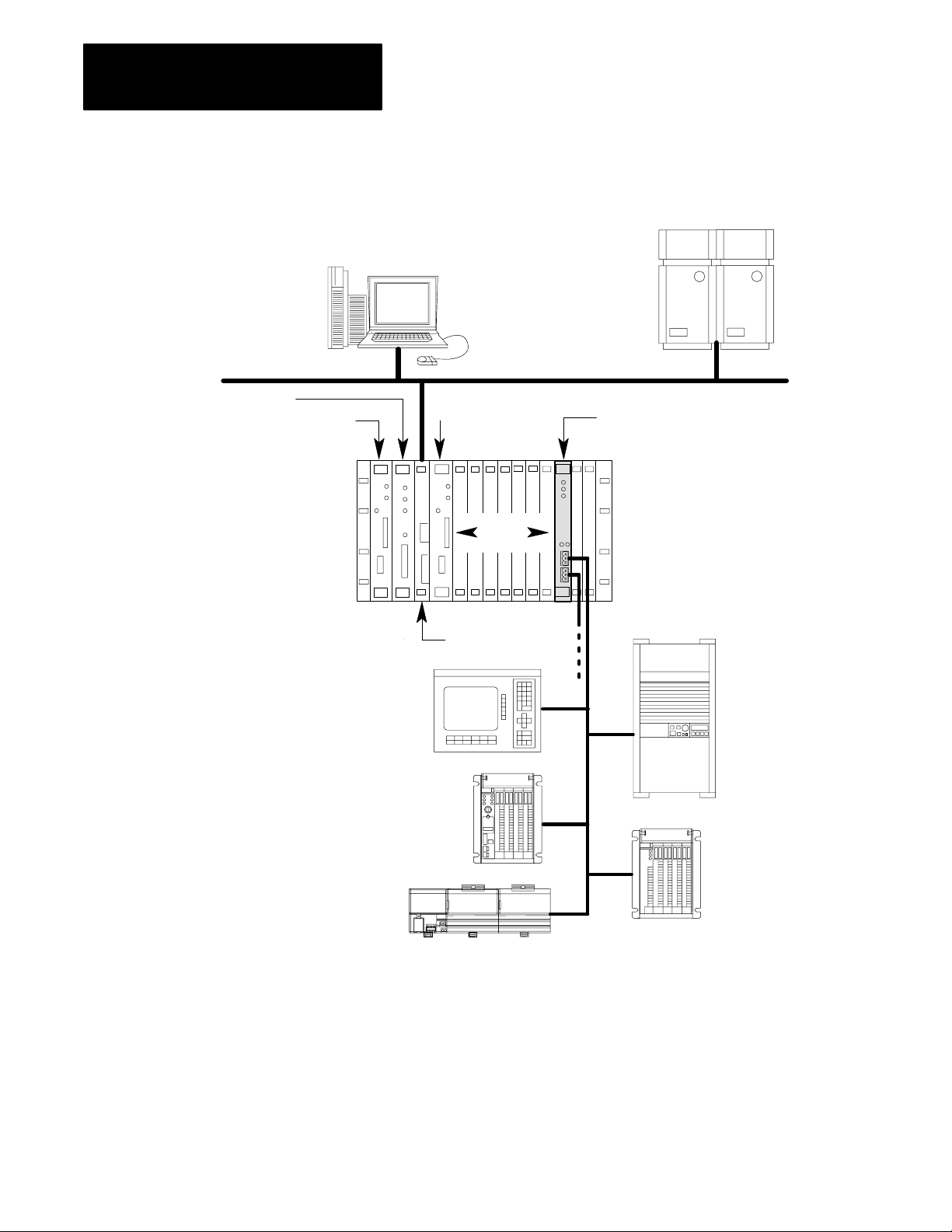
Each scanner channel supports as many as 32 physical adapters (16 logical
racks). Figure 1.2 shows the front panels of the scanners.
6008SV2R
6008SV2R
PWR
BPLN
COM
FLT
AB
Indicators:
power (green)
VMEbus backplane
communication (green)
fault (red)
Indicators:
channel status (green/red)
Channels:
remote I/O channel A
communication port
(factory enabled)
Figure 1.2
Scanner
front panel
6008SV1R
6008SV1R
A
PWR
BPLN
COM
FLT
Table 1.A
Significance of scanner indicators
When this
indicator:
PWR
(power)
green LED
BPLN COM
(backplane
communication)
green LED
FLT
(fault)
red LED
is: it means:
illuminated power is applied to the
module
illuminated for
approximately
a half second
illuminated the scanner board is reset,
a VMEbus access is made
to the scanner board
performing a self test, or a
fault has been detected
Table 1.B
Significance
of channel status
indicators
When the status
indicator is:
off
green is on line, in Run mode, and
the scanner:
is off line
scanning the racks in the scan list
remote I/O channel B
communication port
(factory disabled)
blinking green is on line, in Run mode, and
scanning only some of the racks in
the scan list
red has an unrecoverable fault
blinking red has a recoverable fault
13
Page 12

Chapter
1
Scanner Overview
VMEbus Relationship
The scanner complies with the VMEbus specification (revision C.1) and
responds to VME masters on the VMEbus. The scanner appears as an area
of global VME RAM to other master processors on the VMEbus. This
area contains the I/O image area, control/status area, general data area, and
interrupt ID area.
memory map for one channel
SVcompatible mode SVsuperset mode
output image table
64 words
input image table
64 words
control/status area
16 words
general data area
1872 words
output image table
128 words
input image table
128 words
control/status area
16 words
general data area
112 words
interrupt/VME ID area
32 words
continuous BT write
16 entries
(72 words each)
continuous BT read
32 entries
(72 words each)
interrupt/VME ID area
32 words
For more details on these memory areas, see chapter 5 or 6 for
SV-compatible mode or SV-superset mode, respectively.
There is no direct communication between a VME master processor and
the discrete I/O, rather the VME master processor communicates with the
I/O image table in the scanner (shown above). The VME master processor
reads the status of inputs from the input image table and controls the
outputs by writing data to the output image table.
14
Page 13

Chapter
Scanner Overview
1
These VMEbus transfers are asynchronous to the scanner’s I/O update.
This means there is no way to know exactly when the data being put in the
output image table will be sent to the appropriate I/O rack. Data is sent to
an adapter only when that adapter is being scanned. Best-case timing is if
the data is placed in the output image table just before the specified adapter
is scanned; worst-case timing is if the data is placed in the output image
table just after the specified adapter was scanned. In the worst-case
scenario, the data does not reach the specified I/O rack until the next time
that adapter is scanned.
How the Scanner Responds to VME Signals
The scanner can generate interrupts on any of seven request levels
(IRQ1-IRQ7). When a VMEbus master acknowledges the interrupt, the
scanner replies with a vector (status/id) using the odd 8 bits of the data bus.
Important: The VME master processor might “crash” if there is no
software routine written to process an interrupt from the scanner. Or, you
can use the SETUP command to configure the scanner so that it never
generates interrupts, in case no interrupt software routine has been written.
If the scanner does not generate interrupts, the application program must
“poll” the scanner to see when commands have been processed.
The scanner responds to Data Transfer Bus (DTB) cycles initiated by
masters that transfer data 16 bits at a time or 8 bits transferred in an even
and odd format (D16, D08EO). The scanner works in the 16-bit (short)
addressing mode or the 24-bit (standard) addressing mode.
The scanner responds to common VME signals as follows:
This VME
signal:
SYSFAIL
ACFAIL When the scanner recognizes an ACFAIL signal, it shuts itself down because this
SYSRESET If SYSRESET is asserted on the VMEbus, the scanner resets itself and goes
means:
When the scanner recognizes a SYSFAIL signal, it can either ignore the signal or
shut itself down, depending on how the scanner is configured. When the scanner
shuts down, the I/O serviced by the adapter either resets to a default condition or
holds all of its current values, as determined by switches on the I/O chassis
backplane. When the scanner is faulted or shut down, it asserts SYSFAIL on
the VMEbus.
means that power will soon be gone. When the scanner shuts down, the I/O
serviced by the adapter either resets to a default condition or holds all of its
current values as determined by switches on the I/O chassis backplane.
through its initialization tests. The scanner does not clear (reset to 0) the input
and output image tables. After a SYSRESET signal, you have to wake up the
scanner, the same as a powerup situation.
15
Page 14

Chapter
Scanner Overview
1
For more information, see the VMEbus specification (revision C.1)
published by VITA (VMEbus International Trade Association), 10229 N.
Scottsdale Rd., Suite B, Scottsdale, AZ, 85253, (602) 951-8866. Contact a
VITA representative for a copy.
VMEbus Address Modifier Codes
The scanner can respond to the following VMEbus address modifier codes,
depending on how you configure the scanner’s address space and response
to VME accesses.
How
the Scanner Scans
This code
(hex):
3D
39 standard (A24) nonprivileged access
2D short (A16) supervisory access
29 short (A16) nonprivileged access
means:
standard (A24) supervisory access
The scanner runs asynchronously to other VME master processors. Once
in Run mode, the scanner continuously scans all the adapters in its scan
list. The scan list identifies which adapters to scan and in what order to
scan them. An adapter can appear several times in the scan list. For more
information about using the scan list, see chapter 4.
When the scanner scans an adapter, it brings in digital input data and
places the data in the scanner’s input image table. At the same time, the
scanner sends digital output data to the adapter.
16
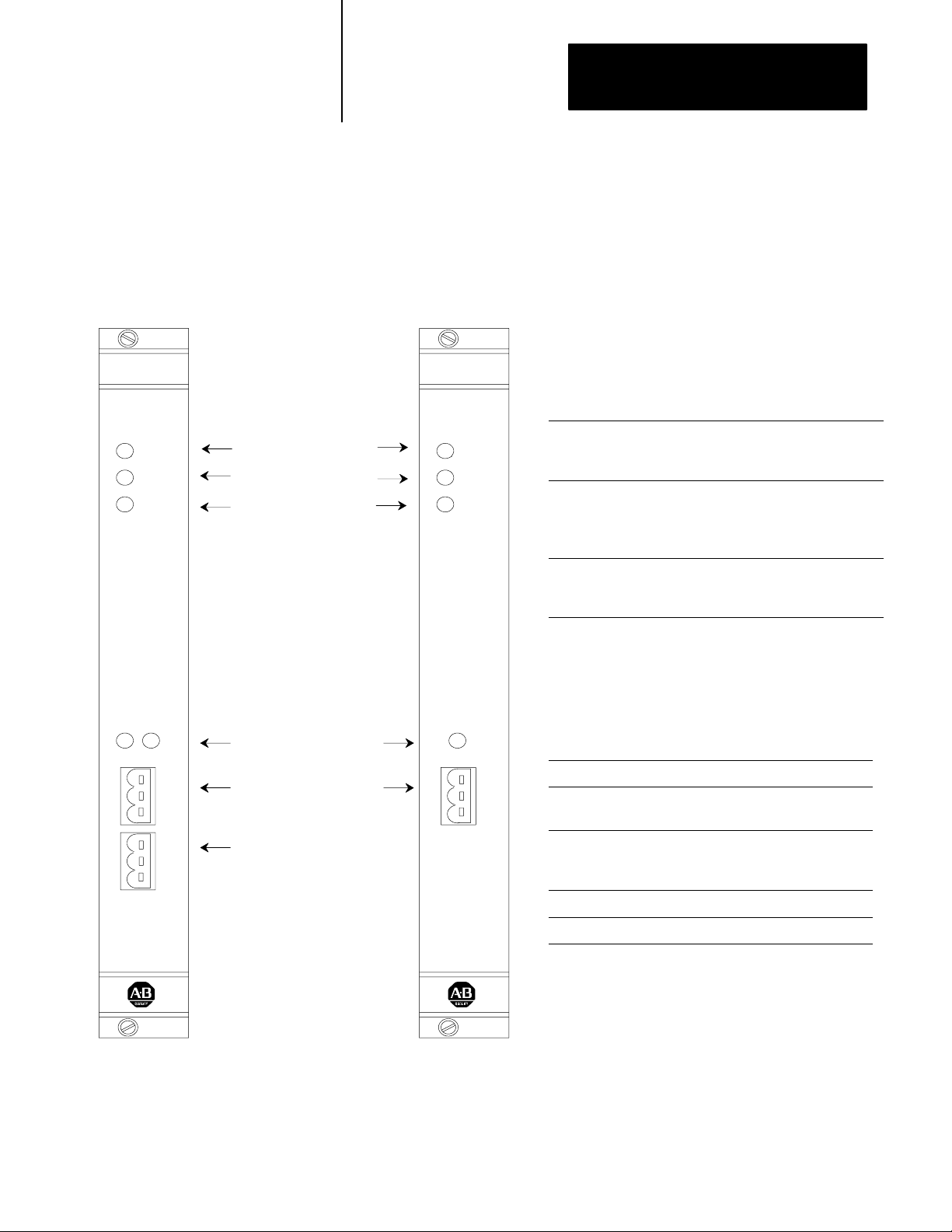
Page 15
VME system with scanner
(scanner using only 1 channel)
Chapter
1
Scanner Overview
remote I/O system
adapter 1
example scan list:
adapter 1
adapter 2
adapter 1
adapter 3
➂ scan adapter 1
scan
list:
adapter 1
adapter 2
adapter 1
adapter 3
➃ scan adapter 3
remote I/O channel A
remote I/O channel B
(6008SV2R only)
➄ if the VME master
processor sent a command,
execute the command and then
return to processing the scan list
if there is no command, continue
processing the scan list
adapter 2
adapter 3
command processing
➁ scan adapter 2
scanner
➀ scan adapter 1
adapter scan
output data
status and input data
scanning the
adapters in the
scan list
17
Page 16

Chapter
Scanner Overview
1
Getting the Scanner's Attention
For a VME master processor to get the scanner’s attention, it must write a
value (any value) to any byte in the scanner’s identification area. This area
is located in the last 64 bytes of the global RAM for each scanner channel.
The scanner gets the attention of a VME master processor by generating a
VMEbus interrupt to which the VME master processor must respond. This
interrupt is sent when the scanner finishes commands that a VME master
processor initiated.
Comparison to
6008SV Scanner
The 6008-SV1R and 6008-SV2R scanners replace and are backward
compatible with the Allen-Bradley 6008-SV VMEbus remote I/O scanner.
The 6008-SV1R and 6008-SV2R scanners offers these improvements:
each remote I/O channel controls as many as 32 adapters
configurable communication rate of 230.4, 115.2, or 57.6 kbps lets you
select I/O scan time
embedded communication microprocessor increases
scanner performance
VME interrupt signals change in the scanner input table
configurable VME operating mode lets you select the scanner features
you need for your application
Important: The SCAN LIST command is the only difference between the
6008-SV1R and 6008-SV2R scanners and the 6008-SV scanner. If you use
that command, you must modify the command to specify the rack size.
The 6008-SV1R and 6008-SV2R also offer improved block transfer
operations. In addition to single block transfer operations, the 6008-SV1R
and 6008-SV2R support continuous block transfer operations. A single
block transfer is a single read or write transfer to a specific intelligent I/O
module. If your application needs to continuously poll a module to receive
up-to-date data, use a continuous block transfer request. The continuous
block transfer requests uses less programming overhead than programming
a single block transfer request each time you need the data.
18
Page 17

Chapter
1
Scanner Overview
Operating
Modes
Before you begin using the scanner, you have several choices to make
concerning how the scanner operates. You need to specify how the scanner
operates in the VME system and how you want to program the scanner.
Selecting VME Operating Mode
The scanner offers two VME operating modes. The mode you select
determines the command set available to the scanner and the memory
structure the scanner uses. You set a switch on the scanner to specify the
operating mode you want.
If you want: select this VME
the scanner to operate exactly as the 6008SV scanner
This mode is compatible with the 6008SV so you can run
previouslydeveloped applications with minor modifications. Select
this mode if you are replacing a 6008SV with a 6008SV2R and do
not want to modify your application.
In any application that uses the SCAN LIST command with the
6008SV scanner, you must modify the command to specify the
rack size.
For more information see chapter 5.
the scanner to use the new commands and additional memory, as
compared to the SVcompatible mode
This mode provides additional features, as compared to the 6008SV.
For more information, see chapter 6.
operating mode:
SVcompatible
SVsuperset
Important: An application developed for one operating mode will not
work in another operating mode.
19
Page 18

Chapter
1
Scanner Overview
Selecting a Programming Mode
Select the appropriate programming mode for programming the scanner.
Table 1.C
Programming
modes
If you want these conditions: select this
• the scanner doesn't send output information to the adapters
• all module outputs are reset (off); outputs are disabled, so they
remain reset
• discrete input information is updated
• the scanner doesn't send blocktransfer requests to the adapters,
but the scanner will queue the requests from the VME
master processor
• the scanner sends output information to the adapters
• all module outputs are held reset (off) outputs are disabled, so they
remain reset
• discrete input information is updated
• the scanner sends blocktransfer requests to the adapters, but
actual outputs are disabled (reset)
• the scanner sends output information to the adapters
• input information is updated
• the scanner sends blocktransfer requests to the adapters
• all outputs are allowed to energize
programming mode:
Program
Test
Run
When your application program first starts the scanner with the SETUP
command, the scanner is in the Program mode. Your program must issue a
SET MODE command to change the scanner to Run mode.
110
Page 19
Chapter
Scanner Overview
1
VME
Master Processor
Watchdog Timer
The VME master processor must issue a valid command to the scanner at
least once in a user-specified time period (the default is 500 msec). If the
scanner fails to see a valid command from a VME master processor in this
time period (as counted by the watchdog timer), the scanner resets itself
and repeats its startup initialization sequence. This causes the I/O racks on
the link to fault within 100 msec and the I/O all turn off or remain in their
last state, depending on the switch setting on the I/O chassis.
You can disable the watchdog timer or change its timeout period with the
SETUP command.
To keep the watchdog from shutting down the scanner, periodically issue a
LINK STATUS command. This command provides the application
program with important diagnostic information about the status of the I/O
link and, at the same time, causes the least amount of overhead for the
scanner to complete the command.
To debug your application program you can select debug mode and disable
the watchdog timer using the SETUP command.
ATTENTION: Unwanted machine action can result from
disabling the VME master processor watchdog. When the VME
master processor watchdog is disabled, the scanner has no way
of knowing that communication has been lost with your VME
master processor and will continue to send data from the output
image table to the output modules.
111
Page 20

Installing the Scanner
Chapter
2
Using This Chapter
Handling the Scanner
This chapter explains how to install the scanner and connect it to a remote
I/O link. For information about programming and using the scanner, use
the flow chart preceding each chapter to determine where to find the
information you need.
If you want to read about: go to page:
handling the scanner
setting switches 21
removing VME backplane jumpers 26
grounding the VME chassis 26
inserting the scanner 27
determining power requirements 27
connecting to the remote I/O link 28
The scanner is shipped in a static-shielded bag to guard against
electrostatic damage. Electrostatic discharge can damage integrated
circuits or semiconductors in the scanner. Avoid electrostatic damage by
observing these precautions.
Remain in contact with an approved ground point while handling the
scanner (by wearing a properly grounded wrist strap).
21
Wrist strap
Setting Switches
Do not touch the backplane connector or connector pins.
When not in use, keep the scanner in its static-shielded bag.
The scanner has several on-board switches you set to configure:
address space
VME operating mode
VME address space
scanner responses to VME accesses
21
Page 21
Chapter
2
Installing the Scanner
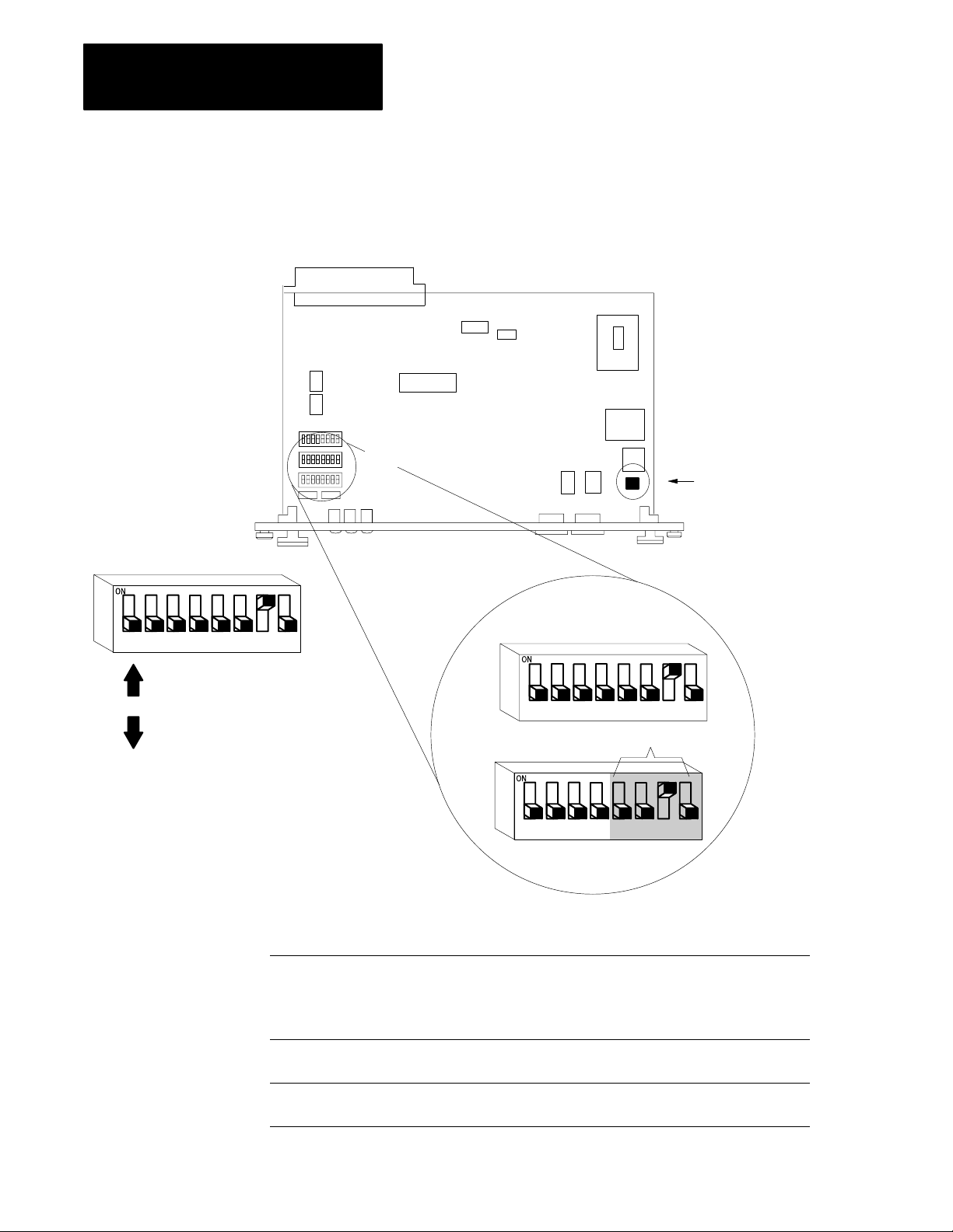
Determine the VMEbus A24/A16 Address Space
Use this diagram and the example to set SW1 and SW2 for the correct
VMEbus address space.
12345678
slide switch pushed up
on = closed = 0
slide switch pushed down
off = open = 1
SW2
SW1
Important: These pins are
for manufacturing use only
- do not jumper these pins.
A23 A22 A21 A20 A19 A18 A17 A16
SW2
12345678
reserved
A15 A14 A13 A12
SW1
12345678
22
In this VME
operating mode:
SVcompatible
SVsuperset A23 through A13 1 channel active
If there are switches not accounted for in a particular address space, such as the switches for A16A23
for SVcompatible, A16 address space, the switch position does not affect scanner operation.
these bits: are valid for this
A23 through A12 1 channel active
A23 through A13 2 channels active
A15 through A12 1 channel active
A15 through A13 2 channels active
A23 through A14 2 channels active
address space:
A24
A16
A24
Page 22
Chapter
2
Installing the Scanner
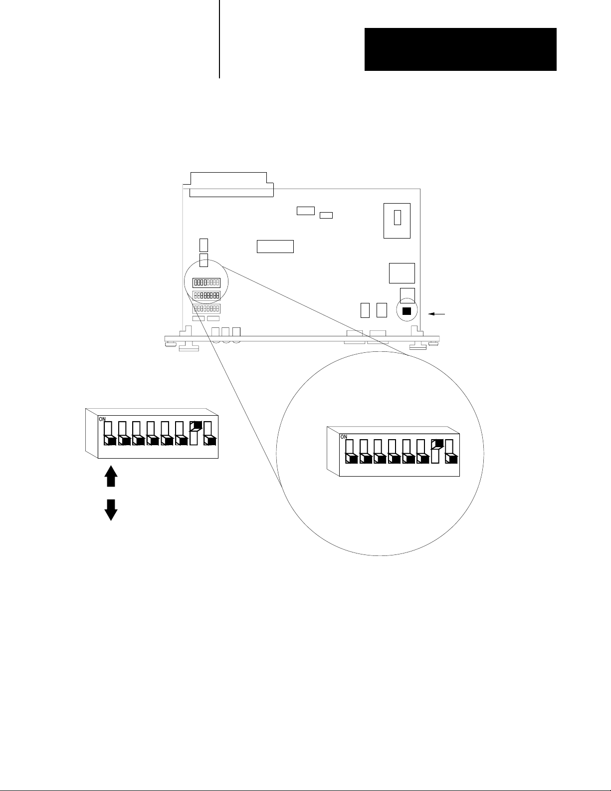
Determine the Operating Mode, Address Space, Scanner Response,
and Rack Configuration
Use this diagram and Table 2.A on page 2-4 to set SW3.
SW3
Important: These pins are
for manufacturing use only
- do not jumper these pins.
12345678
slide switch pushed up
on = closed = 0
slide switch pushed down
off = open = 1
SW3
12345678
23
Page 23

Chapter
2
Installing the Scanner
This switch: configures: with these options:
Table 2.A
settings for SW3
Switch
switch 1, 2, 3
switch 4, 5 VME operating mode switch 4 switch 5
switch 6 VME address space on A16
switch 7 how the scanner responds to
switch 8 which channels are active on only channel A is active
not used set to off
on on SV compatible
on off SV superset
off off reserved
off on reserved
off A24
Select A24 if you select SVsuperset as the VME operating mode.
on responds to nonprivileged and supervisory VME accesses
VME accesses
off responds to supervisory VME accesses
off both channel A and B are active
this switch is ignored if you are configuring the 6008SV1R
(2D, 3D, 29, and 39 address modifiers)
(29 and 39 address modifiers)
24
Page 24
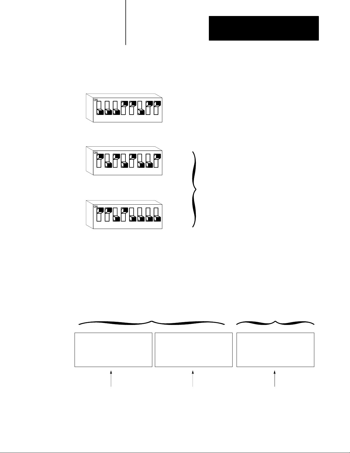
For example:
12345678
12345678
SW3
SW2
Chapter
2
Installing the Scanner
These switch settings specify:
• SVcompatible mode
• A24 address space
• response to both nonprivileged and supervisory access
• only channel A is active
Switch
These switch settings specify VME address 562,000.
SW1
12345678
Specifying VME addresses
You specify the first digit (for A16) or first 3 digits (for A24) of the
address space; the remaining digits are always 0. The switches are set
from left to right. For example, to set the address space at 562,000 (hex) in
A24 with one channel active, set the bits as:
VME address space of 562,000 (hex)
A24 address mode with 1 channel active
SW1SW2
A23 A22 A21 A20 A19 A18 A17 A16 A15 A14 A13 A12
Setting
010101100010
(on) (off) (on) (off) (on) (off) (off) (on) (on) (on) (off) (on)
562
The last three digits in 562,000 (hex) address are already determined
by the scanner, so there are no switches to set.
25
Page 25
Chapter
Installing the Scanner
2
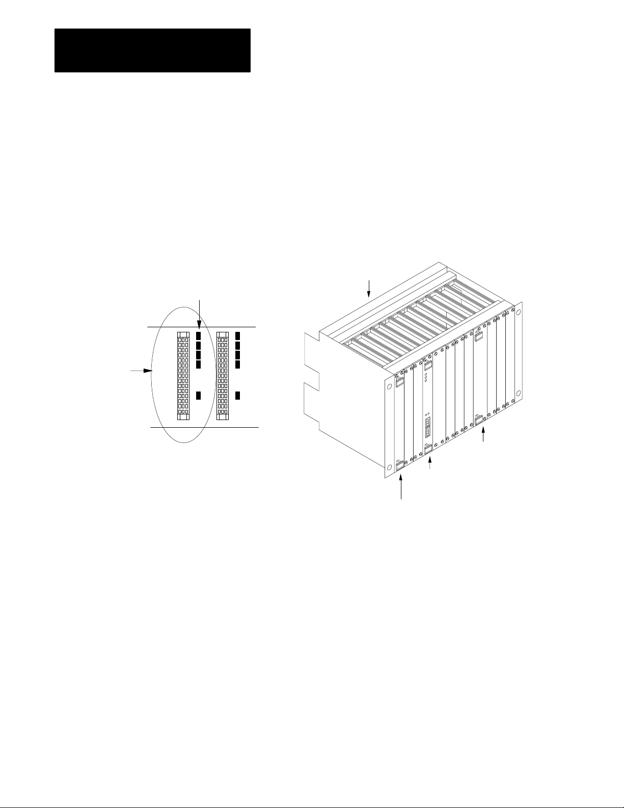
Removing
VME
Backplane Jumpers
one empty slot
(jumpers are installed)
The VMEbus has several daisy-chained control signals. Almost all
VMEbus backplanes contain jumpers for these control signals to allow
systems to operate with empty slots. There are five jumpers per VME
slot, one for each of the four bus-grant arbitration levels and one for the
interrupt-acknowledge daisy chain.
Depending on the backplane manufacturer, the jumpers can be on the
rear pins of the J1 connector or alongside it on the front of the backplane.
The scanner uses 1 slot of the VME backplane. Remove these jumpers
from the slot where you plan to insert the scanner.
remove all the backplane
jumpers in the slot where
you insert the scanner
backplane
Grounding the VME Chassis
other VME module
scanner
CPU
Allen-Bradley makes specific recommendations for properly grounding its
racks so that their operation is as safe and error-free as possible. VME
systems, on the other hand, may have no formal specifications for
grounding the VME chassis frame. Allen-Bradley recommends that you
ground the VME chassis frame and that you connect the logic ground
(common) of the VME power supply to the chassis frame’s earth ground.
The specific procedure for grounding a VME chassis varies depending on
the style of the chassis. Read the Programmable Controller Wiring and
Grounding Guidelines, publication 1770-4.1, for information on how
Allen-Bradley racks are grounded, and try to ground your VME chassis
frame in a similar way.
26
Page 26
Chapter
Installing the Scanner
2
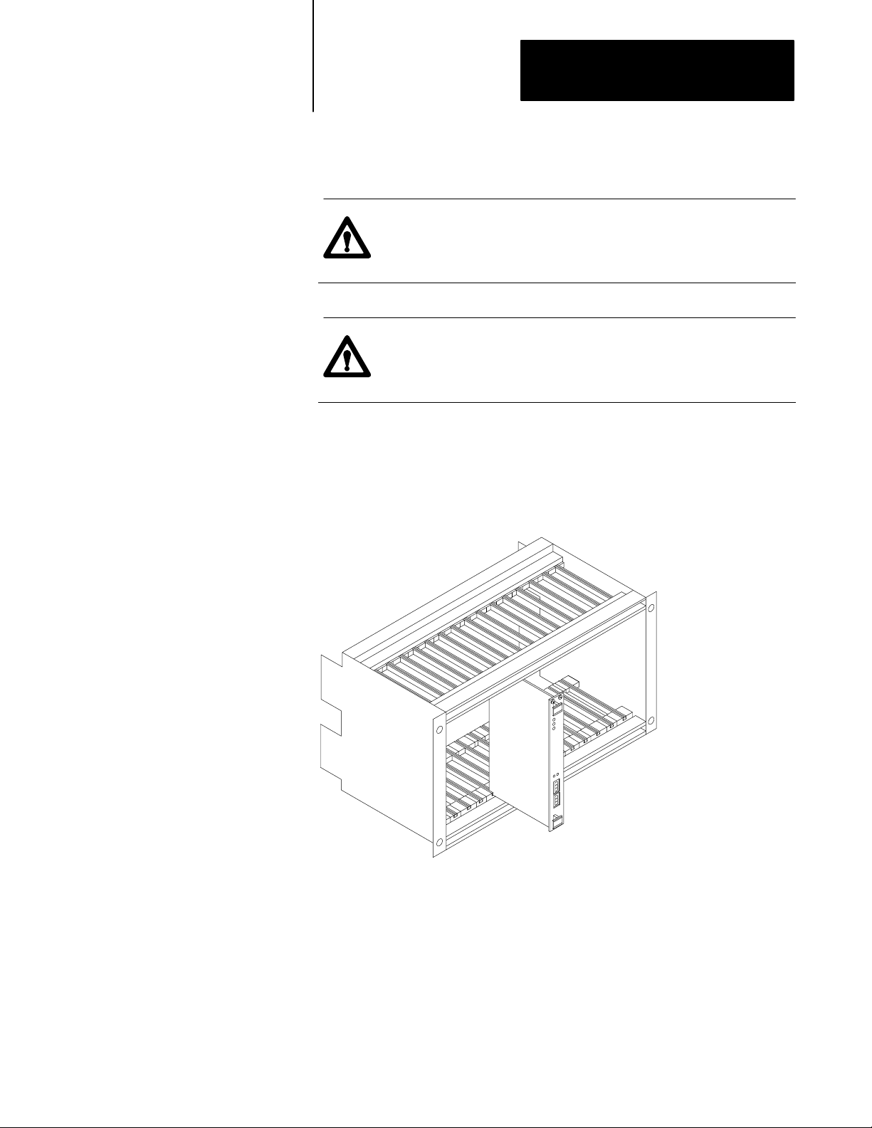
Inserting the Scanner
Insert the scanner in one slot in a 6U (full-height) VMEbus chassis.
ATTENTION: Make sure that your VME system is powered
off. The scanner is not designed to be inserted or removed from
a live system.
ATTENTION: Avoid touching the circuit board
and connectors. You might damage the board, or electrostatic
discharge might damage the board.
Use the VME chassis card guides to slide the scanner into the chassis. Use
firm pressure on the top and bottom handles of the scanner to make its
P1 connector fit firmly into the connector on the backplane. Tighten the
screws on the top and bottom of the front panel to prevent the scanner
from loosening.
Determining PowerSupply
Requirements
The scanner operates on 5V dc @ 2.3A (typical), 2.5A (maximum).
27
Page 27

Chapter
2
Installing the Scanner
Connecting to the
Remote I/O Link
Each scanner channel supports as many as 32 physical adapters. Use
1770-CD (or Belden 9463) cable. Connect a remote I/O network using a
daisy-chain or trunkline/dropline configuration.
Table 2.B
number of devices the scanner supports
Total
In this mode: the maximum number
SVcompatible
SVsuperset 16 32
of logical racks per
channel is:
8 16
and the maximum
number of physical
adapters per channel is:
Important: The maximum cable length for remote I/O depends on the
transmission rate. Configure all devices on a remote I/O link to
communicate at the same transmission rate.
Table 2.C
the correct cable length based on the link'
Choose
A remote I/O link using this
communication rate:
57.6 kbps
115.2 kbps 1,524 m (5,000 ft)
230.4 kbps 762 m (2,500 ft)
cannot exceed this
cable length:
3,048 m (10,000 ft)
s communication rate
For proper operation, terminate both ends of a remote I/O link by using
external resistors. See Table 2.D for information on whether to use a 150W
or 82W terminator.
28
Page 28

Chapter
2
Installing the Scanner
Table 2.D
Terminating
If your remote I/O link:
operates at 230.4 K bit/s
operates at 57.6 or 115.2 K bit/s, and no devices listed below are linked
Scanners 1771SN; 1772SD, SD2;
1775SR, S4A, S4B;
6008SQH1, SQH2
Adapters 1771AS; 1771ASB (series A only); 1771DCM
Miscellaneous 1771AF
connects to any device listed below:
Scanners 1771SN; 1772SD, SD2;
1775SR, S4A, S4B;
6008SQH1, SQH2
Adapters 1771AS; 1771ASB (series A only); 1771DCM
Miscellaneous 1771AF
operates at 57.6 or 115.2 K bit/s, and you do not require over 16 physical devices
the remote I/O link
You can connect a remote I/O link in one of two ways:
trunkline/dropline—from the drop line to the connector screw terminals
on the remote I/O connectors of the scanner
usethis
his
use t
resistor
rating:
82W
150W
the maximum number of
physical devices that you
can connect on the link is:
32 16
16 16
racks that you can
scan on the link is:
daisy chain—to the connector screw terminals on the remote I/O
connectors of the scanner and then to the remote I/O connector screw
terminals of the next remote I/O device
Important: The cable connections for the 6008-SV1R and 6008-SV2R
scanner are opposite from those for the earlier 6008-SV scanner. Make
sure you follow the instructions in Figure 2.1 below.
29
Page 29
Chapter
2
Installing the Scanner
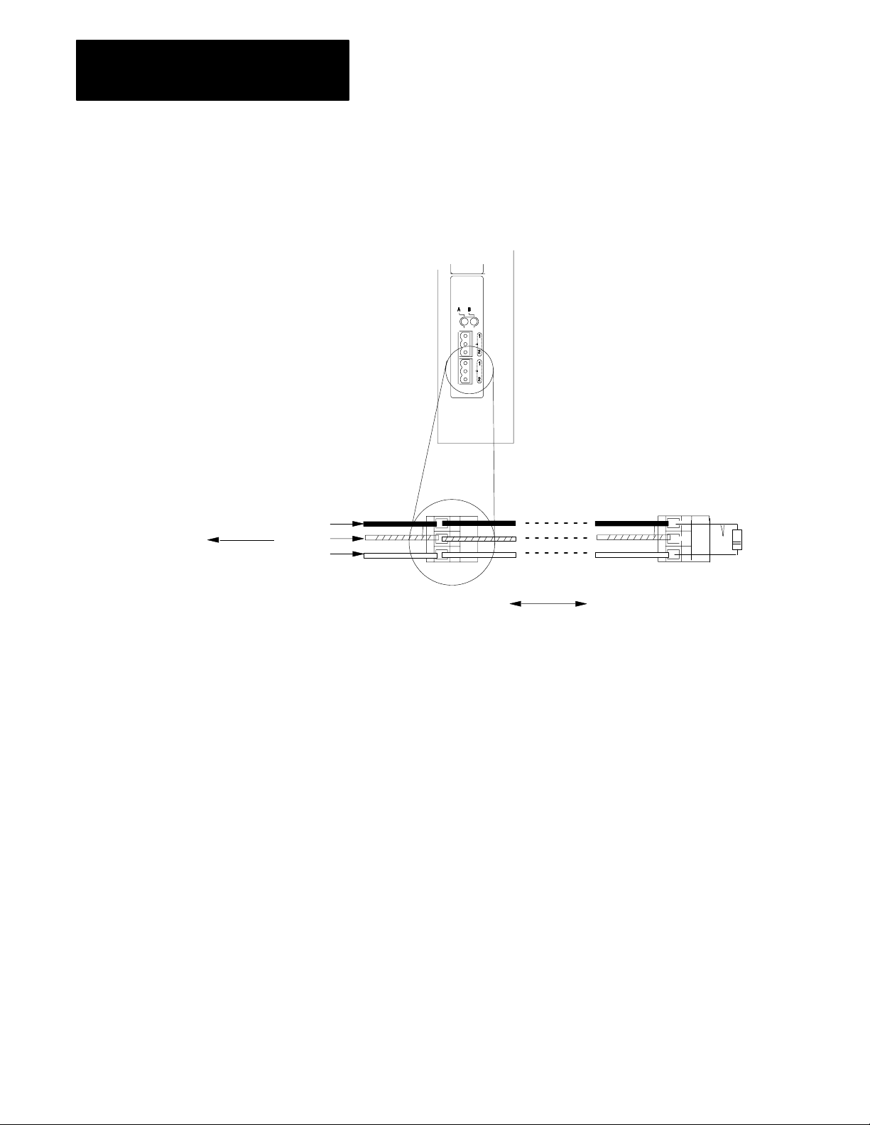
Figure 2.1
remote I/O connections
Make
To connect the remote I/O cable, do the following:
1. Run the cable (1770CD) from the processor to each
remote I/O adapter in the remote I/O system.
2. Connect the signal conductor with blue insulation to the
3pin connector terminal labeled 1 on the scanner and to
each remote I/O adapter in the remote I/O system.
3. Connect the signal conductor with clear insulation to the
3pin connector terminal labeled 2.
4. Connect the shield drain wire to the middle 3pin
terminal (it is not labeled).
5. Tie wrap the remote I/O network cable to the chassis to
relieve strain on the cable.
6. Terminate the remote I/O link by connecting an external
terminator resistor between the remote I/O terminals
labeled 1 and 2.
Important:
Last device on the remote I/O link.
Terminate both ends of a remote I/O link.
To another remote I/O device
Blue
Shield
Clear
1770CD
(Belden 9463)
82Ω or
150Ω
resistor
210
Page 30

Addressing I/O
Chapter
3
Using This Chapter
I/O Addressing Concept
Classification: Term: Relation to memory:
A specific terminal on an I/O module
I/O terminals that when combined occupy 1 word in
the input image table and 1 word in the output
image table
Combinations of bits or I/O groups I/O rack 128 input bits and 128 output bits
This chapter provides an overview of I/O addressing. This chapter also
explains the basics of how the scanner processes discrete I/O and
block-transfer data.
If you want to read about: go to page:
I/O addressing concept
choosing an addressing mode 33
addressing blocktransfer modules 36
assigning racks 37
Each terminal on an input or output module that can be wired to a field
device occupies a bit within the scanner’s input image table or output
image table.
I/O addressing maps the physical location of an I/O module terminal to a
bit location in the processor memory. I/O addressing is just a way to
segment memory:
terminal or
point
I/O group 16 input bits = 1 word in the input image table
The density of an I/O module, i.e., 8point, 16point, 32point,
directly relates to the amount of memory (bits) the module
occupies in memory. For example, a 16point input module
occupies 16 bits in the input image table.
16 output bits = 1 word in the output image table
or
8 input words and 8 output words
or
8 I/O groups
31
Figure 3.1 shows the relationship between an I/O terminal and its location
in scanner memory.
31
Page 31

Chapter
3
Addressing I/O
Figure 3.1
addressing as it relates to an I/O terminal
I/O
rack number 01
I/O group number
A
B
C
D
00
01
02
03
04
05
06
07
10
11
12
13
14
15
16
17
E
Input Module
(1771IAD)
0
Output Image Table
17 16 15 14 13 12 11 10 07 06 05 04 03 02 01 00
17 16 15 14 13 12 11 10 07 06 05 04 03 02 01 00
[
00
17 16 15 14 13 12 11 10 07 06 05 04 03 02 01 00
Input Image Table
word
address
00
01
07
[
00
07
rack number 01
I/O group number
Output Module
(1771OAD)
1
A
B
C
D
00
01
02
03
04
05
06
07
10
11
12
13
14
15
16
17
E
32
Important: The scanner addresses the image table with hexadecimal
values. The addresses depend on the VME operating mode.
Page 32

Chapter
ЙЙЙЙЙЙЙЙ
3
Addressing I/O
Choosing
an
Addressing Mode
For each chassis in your I/O system, you must define how many I/O
chassis slots make up an I/O group (one word each in the input image table
and output image table); this choice is the chassis’ addressing mode.
Choose from among these available modes:
2slot
addressing
2 I/O chassis slots = 1 I/O group = 1 input image word and 1 output image word =
16 input bits and 16 output bits.
16 bits input
1slot
addressing
1 I/O chassis slot = 1 I/O group = 1 input image word and 1 output image word =
16 input bits and 16 output bits.
16 bits output
scanner memory
Rack x
Output Image Table
Word #
x
x
x
x
x
x
x
x
16 bits input and 16 bits output
1/2slot
addressing
1/2 of an I/O chassis slot = 1 I/O group = 1 input image word and 1 output image word =
16 input bits and 16 output bits.
16 bits input and 16 bits output
When you place your I/O modules in the I/O chassis slots, the module’s
density determines how quickly I/O groups form.
Word #
Input Image Table
x
x
x
x
x
x
x
x
33
Page 33

Chapter
3
Addressing I/O
0 1
Input
Terminals
00
01
02
03
04
05
06
07
Group 0
An 8point I/O module occupies
8 bits in a word. See ➀
Input
Terminals
4 5
10
11
12
13
14
15
16
17
8
and 16point examples
2 3
Input
Terminals
00
01
02
03
04
05
06
07
Group 2 Group 3
Two 8point input modules occupy 8
bits of each group. See ➁
6 7
Input
Terminals
00
01
02
03
04
05
06
07
1slot addressing
(1 I/O chassis slot = 1 I/O group = 1 input image word and 1 output
image word = 16 input bits and 16 output bits.)
scanner memory
Rack x
Word #
➂
➃
Word #
➀
➁
➂
➃
Output Image Table
0
1
2
3
4
5
6
7
0017 bits
Input Image Table
0
1
2
3
4
5
6
7
0017 bits
Input
Terminals
00
01
02
03
04
05
06
07
Group 4 Group 5
An 8point input module in group 4
occupies the first 8 bits of input word
4. The 8point output module
occupies the first 8 output bits in
output word 5. See ➂
34
Output
Terminals
00
01
02
03
04
05
06
07
Input
Terminals
00
01
02
03
04
05
06
07
10
11
12
13
14
15
16
17
Group 6 Group 7
16point I/O modules occupy 16 bits,
an entire word, in the image table.
See ➃
Output
Terminals
00
01
02
03
04
05
06
07
10
11
12
13
14
15
16
17
Page 34

Chapter
3
Addressing I/O
32point input module
32point input module
Group 0
32point
examples
0 1
32point I/O modules use the entire word
of their group and borrow the entire word
of the next group. See ➀.
Since the module is in group 0 and the
inputs for group 0 and group 1 are used,
you must:
• install an output module in group 1, or
• leave the slot empty
0 1
32point output module
1slot addressing
(1 I/O chassis slot = 1 I/O group = 1 input image word and 1 output
image word = 16 input bits and 16 output bits.)
scanner memory
Rack x
Word #
➁
Word #
➀
Output Image Table
0
1
2
3
4
5
6
7
0017 bits
Input Image Table
0
1
2
3
4
5
6
7
0017 bits
Group 0 Group 1
Since the input image table for group 1 is unavailable because it is
being used by the input module of group 0, installing a 32point output
module makes use of output image table of group 0 and 1. See ➁.
You can also install 8 or 16point output modules. But you cannot
install another input module since all the input image space for groups
0 and 1 is used by the input module of group 0.
35
Page 35

Chapter
3
Addressing I/O
When planning your system design, consider the densities of the I/O
modules you are using and choose an addressing mode that most
efficiently uses processor memory.
Choose the addressing mode for each I/O chassis by setting the chassis
backplane switch assembly.
Addressing Summary
Addressing
Mode:
2slot
1slot
1/2slot
Guidelines:
• Two I/O module slots = 1 group
• Each physical 2slot I/O group corresponds to one word (16 bits) in the input image table and one word
(16 bits) in the output image table
• When you use 16point I/O modules, you must install as a pair an input module and an output module in
an I/O group; if you use an input module in slot 0, you must use an output module in slot 1 (or it must be
empty). This configuration gives you the maximum use of I/O.
• You cannot use a blocktransfer module and a 16point module in the same I/O group because
blocktransfer modules use 8 bits in both the input and output table. Therefore, 8 bits of the 16point
module would conflict with the blocktransfer module.
• You cannot use 32point I/O modules.
• One I/O module slot = 1 group
• Each physical slot in the chassis corresponds to one word (16 bits) in the input image table and one
word (16 bits) in the output image table
• When you use 32point I/O modules, you must install as a pair an input module and an output module in
an even/odd pair of adjacent I/O group; if you use an input module in slot 0, you must use an output
module in slot 1 (or it must be empty). This configuration gives you the maximum use of I/O.
• Use any mix of 8 and 16point I/O modules, blocktransfer or intelligent modules in a single I/O chassis.
Using 8point modules results in fewer total I/O.
• One half of an I/O module slot = 1 group
• Each physical slot in the chassis corresponds to two words (32 bits) in the input image table and two
words (32 bits) in the output image table
• Use any mix of 8, 16, and 32point I/O or blocktransfer and intelligent modules. Using 8point and
16point I/O modules results in fewer total I/O.
Addressing BlockTransfer
Modules
36
Block-transfer modules occupy 8 bits in the I/O image table. Since all
block-transfer modules are bidirectional, they cannot be used to
complement either input or output modules.
To address: use the:
singleslot modules
doubleslot modules assigned rack number and the lowest group number and 0 for the
assigned I/O rack and group number of the slot in which the
module resides and 0 for the module number
When using 1/2slot addressing, use the assigned rack number
and the lowest group number and 0 for the module number.
module number
Page 36

Chapter
3
Addressing I/O
Assigning
Racks
Design Tip
The number of racks in a chassis depends on the chassis size and the
addressing mode.
If using this
chassis size:
4slot
8slot 1/2 rack 1 rack 2 racks
12slot 3/4 rack 11/2 racks 3 racks
16slot 1 rack 2 racks 4 racks
2slot
addressing,
rack type is:
1/4 rack 1/2 rack 1 rack
1slot
addressing,
rack type is:
1/2slot
addressing,
rack type is:
One I/O rack number is eight I/O groups, regardless of the addressing
mode that you select.
When assigning remote I/O rack numbers, use the following guidelines:
Each scanner channel supports as many as 16 physical I/O adapters.
The number of racks the scanner supports depends on the VME
operating mode.
This operating mode: supports as many as: with a total maximum
SVcompatible
SVsuperset 16 full racks 32
SVadapter 1 rack 0
8 full racks 16
number of adapters:
For example, you can configure 8 racks as:
8
full racks of 128 I/0 each (8 adapters)
or
16 half racks of 64 I/O each (16 adapters)
or
6 full racks of 128 I/O each and 8 quarter racks of 32 I/O each (14 adapters)
37
Page 37

Chapter
3
Addressing I/O
You can assign a remote I/O rack to a fraction of a chassis, a single I/O
chassis, or multiple I/O chassis:
I/O rack 0 I/O rack 1 I/O rack 2
01 23 45 67 01 23 45 67 01234567
16slot chassis, two racksOne
0123
4slot chassis, 1/2 rackOne 2slot chassis, 1/4 rack eachTwo
I/O rack 3
5
4
16slot chassis, one rackOne
67
16466
38
Page 38

Chapter
4
Communicating with Remote I/O
Using This Chapter
Selecting Devices that Y
Can Connect
ou
This chapter provides an overview of remote I/O communication.
If you want to read about: go to page:
selecting devices that you can connect
introduction to remote I/O 42
designing a remote I/O link 43
specifying a scan list 45
processing discrete data 46
processing block data 48
41
These are the devices you can use on a remote I/O link with the scanner.
Category: Product: Catalog
classic PLC5 processors 1785LT
enhanced PLC5 processors 1785L11B
PLC processors
(in adapter mode)
to remote I/O
to remote I/O
operator
operator
interfaces
interfaces
drives
drives
third party
devices
ethernet PLC5 processors 1785L20E
local PLC5 processors 1785L40L
VME PLC5 processors 1785V30B
Direct Communication Module for SLC Processors 1747DCM
SLC 500 Remote I/O Adapter Module 1747ASB
1791 Block I/O 1791 series
FLEX I/O 1794 series
Remote I/O Adapter Module
1slot I/O Chassis with Integral Power Supply and Adapter
2slot I/O Chassis with Integral Power Supply and Adapter 1771AM2
Direct Communication Module 1771DCM
DL40 Dataliner 2706 series
RediPANEL
PanelView Terminal
Remote I/O Adapter for 1336 AC Industrial Drives 1336RIO
Remote I/O Adapter for 1395 AC Industrial Drives
any devices incorporating AB node adapter chip sets under the
ENABLED Technology program
Number:
1785LT2
1785LT3
1785L20B
1785L30B
1785L40B
1785L60B
1785L80B
1785L40E
1785L80E
1785L60L
1785V40B
1785V40L
1771ASB
1771AM1
2705 series
2711 series
1395NA
41
Page 39

Chapter
Communicating with Remote I/O
4
Introduction
to Remote I/O
A remote I/O system lets you control Allen-Bradley I/O that is not within a
VME master processor’s chassis. The SV1R has one remote I/O channel;
the SV2R has two remote I/O channels. Each channel transfers discrete
and block-transfer data with remote I/O devices.
These components make up a remote I/O system:
Figure 4.1
Components
A VME system with an SV1R or SV2R scanner
(only one remote I/O channel is shown being used)
Each scanner channel maintains a scan list that
identifies all the racks connected to that channel.
Remote I/O link cable: Belden 9463
of a remote I/O system
Remote I/O node adapters like the 1771ASB modules
or PanelView operator interfaces addressed
as remote I/O racks.
PLC5 channel or a processor operating as
a remote I/O adapter
42
Page 40

Chapter
4
Communicating with Remote I/O
The scanner keeps a list of all of the devices connected to each channel.
Figure 4.2 shows an example scan list for one channel.
Designing
SV2R
Ch A
Ch B
a Remote I/O Link
Figure 4.2
Rack
Rack 2
Rack 3
scan list
1
Ch B Scan List
Rack
Address
1
2
3
In this example, channel B continually scans the three racks in its scan list.
Starting
Group
0
0
0
Rack
Size
Full
1/2
Full
Range
010017
020023
030037
Example
The steps for setting up a remote I/O system are:
Step: See:
1.configure the remote I/O adapter devices
2.layout and connect the remote I/O link cable
3.specify a scan list page 45
the device's user manual
•page 43 for design
•your adapter's installation information
Designing a remote I/O link requires applying:
Design Tip
remote I/O link design guidelines
cable design guidelines
Link Design Guidelines
Keep these rules in mind as you design remote I/O links:
All devices connected to a remote I/O link must communicate using the
same communication rate. The rate you choose depends on the VME
operating mode:
This VME operating mode: supports these
SV compatible
SV superset 57.6 kbps
communication rate:
57.6 kbps
115.2 kbps
115.2 kbps
230.4 kbps
43
Page 41

Chapter
Communicating with Remote I/O
4
Two channels on the same scanner cannot scan the same partial or full
rack address. Assign unique partial and full racks to each channel.
You can split rack addresses between scanner channels; however, issues
arise when performing block-data transfer. If you split remote rack
addresses between scanner channels, channel A has priority over
channel B.
A scan list can have a maximum of 16 rack numbers or a maximum of
64 physical devices connected to it using 82-Ω termination resistors.
Design Tip
Cable Design Guidelines
Specify 1770-CD (Belden 9463) cable. Connect a remote I/O network
using a daisy chain or trunk line/drop line configuration.
Important: The maximum cable length for remote I/O depends on the
transmission rate. Configure all devices on a remote I/O link to
communicate at the same transmission rate.
For trunk line/drop line configurations, use the 1770-SC station connectors
and follow these guidelines:
the length of the trunk line cable depends on the communication rate
the length of the drop cable is 30.4 m (100 cable-ft)
For more information about designing trunk line/drop line configurations,
see the Data Highway/Data Highway Plus/Data Highway II/Data
Highway-485 Cable Installation Manual, publication 1770-6.2.2.
For daisy chain configurations, determine the total cable length you need.
A remote I/O link using this
communication rate:
57.6 kbps
115.2 kbps 1,524 m (5,000 ft)
230.4 kbps 762 m (2,500 ft)
cannot exceed this
cable length:
3,048 m (10,000 ft)
44
Page 42

Chapter
4
Communicating with Remote I/O
For proper operation, terminate both ends of a remote I/O link by using
external resistors. Use either a 150W or 82W terminator.
Table 4.A
Selecting
If your remote I/O link:
operates at 230.4 K bit/s
operates at 57.6 or 115.2 K bit/s, and no devices
listed below are linked
Scanners 1771SN; 1772SD, SD2;
1775SR, S4A, S4B;
6008SQH1, SQH2
Adapters 1771AS;
1771ASB (series A only);
1771DCM
Miscellaneous 1771AF
connects to any device listed below:
Scanners 1771SN; 1772SD, SD2;
1775SR, S4A, S4B;
6008SQH1, SQH2
Adapters 1771AS;
1771ASB (series A only);
1771DCM
Miscellaneous 1771AF
operates at 57.6 or 115.2 K bit/s, and you do not
require over 16 physical devices
the external resistor
use this resistor
rating:
82W
150W
the maximum number of
physical devices that
you can connect on
the link is:
32 16
16 16
racks that you can
scan on the link is:
Specifying
a Scan List
The scan list is a map of the I/O devices the scanner channel scans. To
create the scan list, use either of these commands:
If you want: use this command:
the scanner to poll all available adapter addresses and assemble a
list with one entry for each adapter
in SVcompatible mode, there will be a maximum of 16 entries in
the scan list; in SVsuperset mode , there will be a maximum of 32
entries in the scan list
to create the scan list manually
add adapters multiple times in the scan list
there can be a maximum of 64 entries in the scan list, as long as
there are only 16 distinct physical adapters
AUTOCONFIGURE
SCAN LIST
45
Page 43

Chapter
Communicating with Remote I/O
4
Processing
Design Tip
Discrete I/O
If you need multiple updates to an I/O device during an I/O scan, enter a
logical address in the scan list more than one time. Do not assign the same
partial or full rack address to more than one channel in scanner mode.
Each channel must scan unique partial and/or full rack addresses.
The automatic configuration always displays the actual hardware
configuration, except for racks that have their global-rack inhibit bit set. In
this case, the global-rack bit overrides the automatic configuration.
Discrete I/O devices include such external devices as:
switches
relay contacts
indicator lights
control relays
motor starters
A scanner channel exchanges discrete data (digital and analog) with remote
I/O node adapters like 1771-ASB modules via the scanner I/O image table
(Figure 4.3).
Figure 4.3
I/O scan
Remote
Rack 3
Rack 2
Rack 1
adapteradapter adapter
scanner
I/O table
data exchange
VME
master
processor
46
The remote I/O scan is the time it takes for the scanner to
communicate with all of the entries in its scanlist once.
Page 44

Chapter
4
Communicating with Remote I/O
Important: The remote I/O scan for one channel is independent of and
asynchronous to the remote I/O scan for the other channel.
The status of the discrete devices is represented by a single bit in an input
or output group (word). The scanner is related to these devices as shown
in Figure 4.4.
Figure 4.4
Relationship between the scanner and I/O
The
VMEbus Subrack
VMEbus
VME
master
processor
backplane
scanner
channel
1771 I/O
chassis
1771
adapter
I/O
input
modules
output
modules
motor starter
pushbutton switch
remote
I/O link
Up to 13 more
I/O adapters
1771 I/O
chassis
PLC5
processor
in adapter
mode
operator
interface
terminal
input
modules
output
modules
15383
An external device, such as the switch shown above, causes an input of a
discrete input module to turn on. This sets a bit to a “1” condition in the
I/O module. The next time the I/O adapter scans the module, the new
information is reported to the adapter. When the scanner scans the adapter,
the corresponding bit in the I/O image table is set to a condition that
reflects the status of the external device, the switch.
47
Page 45

Chapter
Communicating with Remote I/O
4
A VME master processor then reads the input image information from the
global RAM via the VMEbus.
To generate an output, a VME master processor sets a specific bit in the
I/O image table in the scanner’s global RAM, corresponding to the desired
output device, for example a control relay.
The scanner updates the adapter during the next scan cycle. The adapter
sets the appropriate bit in the output module and the discrete output device
energizes the control relay.
Processing
Block Data
Rack 3
In addition to discrete data, the scanner can also exchange block data with
remote I/O. Block transfers are the communication of data blocks (files)
between the scanner and intelligent I/O modules. These are any I/O
modules that respond to read or write block transfers. These modules
handle data such as analog input, analog output, positioning, and
communication data.
Block-transfer instructs the scanner to transfer as many as 64 words of data
to/from a selected I/O module. The operating mode of the scanner
determines how many block-transfer requests the scanner can queue as
many as 42 requests when operating in SV-compatible mode; only 1
request when operating in SV-superset mode. Figure 4.5 shows how the
scanner handles a block-transfer.
Figure 4.5
Blocktransferring
data to remote I/O
scanner
48
Rack 2
Rack 1
adapteradapter adapter
blocktransfer
sent to adapter
scanner
block
transfer
table
Q
A
Q = queue
A = active
blocktransfer
request
VME
master
processor
Page 46

Chapter
Communicating with Remote I/O
4
The scanner processes block-transfers differently depending on the VME
operating mode. In general though, block-transfer allows the VME master
processor to read or write up to 64 16-bit words from an adapter.
In SV-compatible mode
The scanner processes single block-transfer operations. You must program
a read or write command for each data transfer in your application. The
scanner can queue as many as 42 block-transfer requests from the VME
master processor.
In SV-superset mode
The scanner processes single block-transfer operations and continuous
block-transfer operations. The single block-transfer operations work the
same as in SV-compatible mode. The only difference is that the scanner
can only queue one request from the VME master processor. Use
continuous block-transfer requests for applications that need to
continuously poll an adapter. The continuous block-transfer requests uses
less overhead than programming a single block-transfer request each time
you need the data.
For specifics on block-transfers based on VME operating mode, see
chapter 5 or 6 for SV-compatible or SV-superset mode, respectively.
Understanding the BlockTransfer Sequence
The VME master processor and scanner alternately access the scanner’s
global RAM while transferring a block transfer. See Figure 4.6 and
Figure 4.7.
49
Page 47

Chapter
4
Communicating with Remote I/O
Output Image Table
Input Image Table
Operating Status Word
Confirmation Status Word
Command Word
Address Word
BT Tag Word
Figure 4.6
Blocktransfer
❶
VME
master
processor
The scanner writes a
result code in the
confirmation status word.
See chapters 5 or 6.
sequence - sending a request
The VME master processor sends a
BT WRITE request to scanner
BT#n
The scanner copies the request parameters and data
into its internal queue. In SVcompatible mode, the
scanner can queue as many as 42 blocktransfer
requests; in SVsuperset mode, the scanner can queue
only one blocktransfer request.
❷
scanner
queue
BT#a
BT#b
BT#n
During the adapter scan, the scanner polls each adapter in the scan
list. If a blocktransfer is pending for that adapter, the scanner sends a
blocktransfer request to the adapter. The scanner doesn't receive or
send the block data until the next scan. The scanner transmits only
one blocktransfer request per adapter per scan.
❸
scan n
scanner
BT#n
1771 I/O
chassis
adapter
#n
input
modules
output
modules
410
Page 48

Chapter
4
Communicating with Remote I/O
Figure 4.7
Blocktransfer
On the previous adapter scan, the scanner sent a block
transfer request. During this scan, the adapter returns the
response data to the scanner.
❹
scan n + 1
1771 I/O
chassis
adapter
#n
input
modules
output
modules
BT
data
sequence - receiving data from a completed transfer
The scanner:
1. tests and sets the semaphore
2. places the blocktransfer data in the general data area
3. places a completion code in the confirmation area
4. provides the proper blocktransfer tag number
5. generates a VME interrupt (optional)
❺
BT#n
scanner
BT
data
scanner's global RAM
The application program must move the blocktransfer
data out of the general memory area and clear the
semaphore so other blocktransfers can be completed.
❻
BT#n
BT
data
VME
master
processor
411
Page 49

Chapter
Communicating with Remote I/O
4
Sending Multiple BlockTransfers to the Same Adapter
The scanner can send as many block-transfer requests as it needs to an
adapter (which corresponds to 1 physical rack), but it can only send one
block-transfer request to a rack per scan. To achieve the most efficient
block-transfers, arrange your intelligent I/O modules in multiple racks.
Another method to achieve faster block-transfers is to use the SCAN LIST
command so that a rack with several intelligent I/O modules is scanned
more often through multiple listings in the scan list.
The scanner keeps track of each block-transfer request by its unique tag
number. You assign the tag number when you configure the block-transfer
command. When a block-transfer command completes, the scanner returns
the tag number along with the data so your application can determine
which block-transfer completed.
In SV-compatible mode
Each scanner channel can queue as many as 42 block-transfer requests.
Each request has a block-transfer tag number that you assign in your
application program. When a specific block-transfer is complete, the
scanner sends the block-transfer tag number back to the VME master
processor, along with the data. This way, your application program will
know which block-transfer completed, since block-transfers do not
necessarily get completed in the same order they are requested.
In SV-superset mode
The scanner still processes a block-transfer request the same way as in
SV-compatible mode, but each scanner channel can queue only 1
block-transfer request. If you need multiple block-transfers to the same
adapter, use the continuous block-transfer operation. It achieves the same
result as sending several single block-transfer requests and it also reduces
programming overhead.
Before initializing a continuous block-transfer requeues to an I/O modules,
try a single block-transfer to the I/O module to verify the block-transfer
parameters. After verifying the single block-transfer, use those parameters
in a continuous block-transfer request.
412
Page 50

Chapter
Communicating with Remote I/O
4
Maintaining Block Integrity
To maintain block integrity within the global RAM, use bit 7 of the
semaphore byte. The semaphore byte is in the control/status area of global
RAM for each channel. See chapters 5–6, depending on the operating
mode you select for the scanner.
At power up, when the scanner is turned on, the semaphore bit is 0 (reset).
When the scanner completes a block-transfer, it tests and sets the
semaphore. If the semaphore was reset, the scanner loads status (either
confirmation or error) into the confirmation status word and optionally
interrupts the VME master processor to notify it of pending status. If the
semaphore was set, the scanner holds the block-transfer information until
the semaphore is reset by a VME master processor.
After receiving the status, the VME master processor must copy the data
from the global RAM and reset the semaphore.
Rack n
Rack 2
Processing One Block Transfer Request
The order in which the scanner sends block-transfer requests to adapters
depends on the scanner’s scan list. The scan list tells the scanner when to
poll an adapter; an adapter can be in a scan list multiple times.
Figure 4.8
Adapter
scan sequence
adapteradapter adapter
remote I/O
buffer
❶scanner sends discrete output data,
which includes a code identifying
upcoming blocktransfer, if any
scanner
❷adapter accepts output data and sends
discrete input data, which includes a
status bit that tells the scanner to send
the blocktransfer
❸scanner recognizes status bit and
sends blocktransfer
Rack 1
❹adapter receives blocktransfer and
processes the request
413
Page 51

Chapter
Communicating with Remote I/O
4
Important: Do not accidentally write data in the output image table in
global RAM of the scanner. Any data in an output byte for an intelligent
I/O module overrides the scanner block-transfer command and ruins any
block-transfer request. Such an error is detected as a bit being set in the
operating status word identifying an unsolicited block-transfer.
When the scanner is done with the block-transfer, it tests and sets the
semaphore, places the necessary data in the general data area, places a
completion code in the confirmation status byte, provides the
block-transfer tag number, and generates a VMEbus interrupt. If the
scanner sees that the semaphore is already set, it holds the block transfer
data until the semaphore is reset.
Your application should copy the block-transfer data from the general data
area and clear the semaphore.
BlockTransfer Timeout
If the block-transfer request does not complete within 4 seconds of the
VME master processor sending the request to the scanner, the scanner:
1. tests and sets the semaphore
2. dequeues the failed request
3. places an error code in the confirmation status word
4. copies the correct tag value
5. optionally interrupts the VME master processor to indicate that the
block-transfer requests timed out.
The VME master processor then retrieves the result code and clears
the semaphore.
The most common failure of a block-transfer is a block timeout, error
code 23 (hex) in the confirmation status word. This error occurs if the
block-transfer does not complete within 4 seconds of the initial request.
This 4-second value is not variable.
Another frequent reason a block-transfer times out is because an incorrect
intelligent module address is given to the scanner. Another common
mistake is to put an incorrect value for the length of data words. The value
for the length of data words must equal the number of words the I/O
module expects to transfer. If these two values are not the same, the
transfer will never happen.
414
The best way to avoid a block-transfer timeout is to give the scanner a
transfer length of zero. This lets the I/O module decide how many words
to send. When the transfer completes, the I/O modules replaces the 0 in
the length of data words with the actual number of how many words
were transferred.
Page 52

Chapter
5
Operating in SVCompatible Mode
Using This Chapter
The SV-compatible mode supports these features:
each channel supports as many as 8 logical racks (16 physical adapters)
the global data area is 1872 words long
using the SETUP command, you can enable or disable the
VME-master-processor watchdog timer; change the timeout interval of
the watchdog timer; select the command complete interrupt level and
status ID; select whether to monitor SYSFAIL conditions; and select a
communication rate of 57.6 or 115.2 kbps
Use this mode if you are replacing a 6008-SV scanner and want the
6008-SV1R or 6008SV2R scanner to operate exactly as the scanner you
are replacing. Your programs for the 6008-SV scanner work for the
6008-SV1R or 6008-SV2R scanner. However, you need to change any
reference in your application to the VME ID for the 6008-SV scanner to
the VME ID for the 6008-SV1R or 6008-SV2R scanner.
Important: The SCAN LIST command uses two bits to identify rack size.
These bits were not required for the 6008-SV. If you are migrating your
application from a 6008-SV to a 6008-SV1R or 6008-SV2R, make sure to
set these additional bits. See page 5-13.
Addressing Global RAM
This chapter describes the SV-compatible mode.
If you want to read about: Go to page:
addressing global RAM
command summary 56
Both the VME master processor and the scanner can read and write to the
scanner’s VME global RAM. The global RAM structure depends on the
VME operating mode of the scanner. Figure 5.1 shows the general
structure for the SV-compatible operating mode. Page 5-3 shows the
specifics of the structure for channel A.
51
51
Page 53

Chapter
5
Operating in SVCompatible Mode
Figure 5.1
General
Channel A Channel B
byte offset
(hex)
000 output image table
64 words
080
100
120
FC0
input image table
64 words
control/status area
16 words
general data area
1872 words
interrupt/VME ID area
32 words
structure of global RAM for SV
compatible mode
(6008SV2R scanner only)
byte offset
(hex)
1000
1080
1100
1120
1FC0
output image table
64 words
input image table
64 words
control/status area
16 words
general data area
1872 words
interrupt/VME ID area
32 words
The physical address is the base address plus the byte offset.
Important: Add 1000 (hex) to channel A addresses to get the
corresponding addresses for channel B.
52
Page 54

global RAM structure for SVcompatible mode
Channel A
Chapter
5
Operating in SVCompatible Mode
Rack 0, Output Group 0
Rack 0, Output Group 1
Rack 0, Output Group 2
Rack 0, Output Group 3
Rack 0, Output Group 4
Rack 0, Output Group 5
Rack 0, Output Group 6
Rack 0, Output Group 7
Rack 1, Output Group 0
Rack 1, Output Group 1
Rack 7, Output Group 6
Rack 7, Output Group 7
Rack 0, Input Group 0
Rack 0, Input Group 1
Rack 0, Input Group 2
Rack 0, Input Group 3
Rack 0, Input Group 4
Rack 0, Input Group 5
Rack 0, Input Group 6
Rack 0, Input Group 7
Rack 1, Input Group 0
Rack 1, Input Group 1
byte offset (hex)
00007F
output image table
64 words
0800FF
input image table
64 words
continued
not used
010A-011B not used
not used
General Data Area
Reset Words
operating status
confirmation
command
address
BT tag
semaphore
length of data
byte offset (hex)
10011F
control/status
16 words
120FBB
general data area
1872 words
FBCFBF
Rack 7, Input Group 6
Rack 7, Input Group 7
continued
contains 1 ASCII character/word
V.M.E.I.D.A.-.B.6.0.0.8.-.S.V.2.R.
or
V.M.E.I.D.A.-.B.6.0.0.8.-.S.V
.A. .A.
.1.R. .A. .A.
FC0FFF
Table 5.A describes the components of global RAM.
scanner interrupt
and VME ID area
32 words
53
Page 55

Chapter
5
Operating in SVCompatible Mode
Table 5.A
Descriptions
This area: stores the:
input and output image tables
control/status area operating status byte reflects the current status of the scanner (Figure 5.2)
general data area contains input parameters and result data for scanner commands
scanner interrupt and VME ID interrupt from the VME master processor to the scanner
input and output data for as many as 8 logical I/O racks with no more than 16 adapters.
confirmation status
byte
command byte identifies the command the VME master processor wants the scanner to
address byte contains I/O rack, group, and slot parameters for block transfer commands
blocktransfer tag byte provided by the VME master processor to uniquely identify each
semaphore byte provides for the integrity of command requests, command responses, and completed
length of data byte specifies the amount of data associated with a command or response
The scanner interrupt area and VME ID area can be read anytime without causing an interrupt to the scanner.
It contains 32 words in which the odd (lower byte) only is used; the information is an ASCII character string:
V.M.E.I.D.A.-.B.6.0.0.8.-.S.V.2.R. .x. .y
where .x. .y. are the series and revision levels of the scanner. For example:
V.M.E.I.D.A.-.B.6.0.0.8.-.S.V.2.R. .A. .A. for series A, revision A.
Writing to any byte in this area interrupts the scanner. The scanner then looks at the command byte to
determine which command to execute.
All even bytes have the value 0xFF; all odd bytes without ASCII characters have the value 0x00.
of the global memory areas
lets the VME master processor poll the scanner's status without interrupting
ongoing operations
contains the result of the executed command
A result of 00 (hex) indicates the command completed successfully. See chapter 9
for a list of error codes.
execute next
For more information, see BT READ command on page 525 or BT WRITE
command on page 527.
blocktransfer request
block transfers
If bit 7 is set, a VME master processor is using the control/status and general data
area or the scanner just completed a blocktransfer and set the semaphore so no
other VME master processor will overwrite the data. If the semaphore is set because
of a blocktransfer, the appropriate VME master will know to come and retrieve the
data and reset the semaphore. If the semaphore bit is clear, the general data area is
available for access by any VME master processor.
Important: A VME master processor doesn't use the semaphore when it accesses
the I/O image table. The VME master processor can access the I/O image
table anytime.
For command requests, the scanner returns status, either confirmation or error, when
the command is complete. When the VME master processor receives the
confirmation status, it must retrieve the data from the general data area and clear
the semaphore.
Important: Only 1 command can be issued at a time. A status confirmation or error
must be received before a new command is issued.
Only the lower byte is used. Interpret the length of data based on the context of the
requested command or received confirmation (i.e., number of words for
blocktransfers and bytes for scanner management requests).
.
or V.M.E.I.D.A.-.B.6.0.0.8.-.S.V.1.R. .x. .y.
54
Page 56

Chapter
5
Operating in SVCompatible Mode
Operating Status Byte
The operating status byte holds scanner status information for the VME
master processor. The scanner updates this byte every time it completes
either a block-transfer or a command. The master processor can clear bits
4 and 7; the remaining bits are read only. The structure is as follows:
Figure 5.2
Structure
These
bits:
bits 0-2
bit 3 If the debug mode bit is set by the scanner, the scanner cannot
bit 4 The scanner sets bit 4 when it detects an unsolicited
Considerations: These
These bits specify the programming mode of the scanner.
These bits are mutually exclusive - the scanner can be in only
one of these modes.
be shutdown by the internal watchdog.
ATTENTION: Unwanted machine motion can result from
disabling the VME master processor watchdog. Only use the
debug mode when you are debugging the application program
for the VME master processor.
blocktransfer. An unsolicited blocktransfer results if a VME
master processor accidentally writes discrete information to an
output image table byte that is mapped to an I/O slot requiring
a block transfer.
When this bit is set, take action to correct this situation because
it can seriously degrade scanner response time. The scanner
can only set this bit; the VME master processor must clear it.
of the operating status byte
76543210
bits:
Considerations:
bits 5 If bit 5 is set, the scanner has at least one blocktransfer
request in its internal queue. When the queue is empty, the
scanner clears the bit.
bit 6 If bit 6 is set, at least one adapter has faulted, lost power, or
has been dropped from the I/O link. The VME master
processor can issue the LINK STATUS command for fault
details. When all the adapters in the scan list are cleared of
faults or have been brought back on line, the scanner will clear
this bit.
bit 7 If bit 7 is set, an adapter's operating status has changed. The
scanner uses this bit to tell VME master processors of a
change in status of one of the adapters on the I/O link. An
example is that if an operator temporarily pulled the swing arm
from an adapter, the scanner would lose communications with
that adapter. Maybe the operator could quickly put it back and
the status LED and the adapter fault bit (bit 6) would say
everything is working properly, but the adapter fault change bit
would be left set, indicating that an adapter was temporarily off
line. A VME master processor can issue the LINK STATUS
command to make sure the I/O link and all adapters are
operating properly upon seeing this bit set. Only the scanner
can set this bit. The VME master processor must clear it.
55
Page 57

Chapter
5
Operating in SVCompatible Mode
Command
If you want to: Use this command: With this
set the baud rate, watchdog rate, VMEbus interrupt level, how
the scanner responds to SYSFAIL, and whether the scanner
issues VMEbus interrupts
establish a default scan list and provide status of the I/O
system to the VME master processor
establish your own scan list SCAN LIST 11 program 513
establish a fault dependent group structure FAULT DEPENDENT GROUP 12 program 516
change the operating mode of the scanner SET MODE 20 program
check adapter status and the scan list without affecting
scanner operation
transfer a block of data from a specified I/O module to
the scanner
transfer a block of data from the scanner to a specified
I/O module
cause the scanner to reset itself RESET none program
Summary
The SV-compatible mode of the scanner supports these commands:
command byte
(hex):
SETUP 13 program 57
AUTOCONFIGURE 10 program 59
LINK STATUS 21 program
BT READ 01 program
BT WRITE 02 program
The scanner must
be in this
programming
mode:
test
run
test
run
test
run
test
run
test
run
See page:
519
521
525
527
529
Waking up the scanner
When the scanner is first turned on, it does a self-test and then goes to
sleep. A VME master processor must wake the scanner up by interrupting
it (writing any value to the scanner’s ID area), which moves the scanner
from sleep mode to program mode. Chapter 7 explains how to wake up
the scanner. Chapter 8 provides additional programming examples.
56
Page 58

SETUP
command
byte 13
description
Chapter
5
Operating in SVCompatible Mode
SETUP configures the scanner. The scanner must be in Program mode to
execute this command. This is normally the first command sent to
the scanner.
channel A
general data
channel A
control/status
01 = 57.6 kbps (default)
02 = 115.2 kbps
FF = no change
01 = disable watchdog
xx = enable watchdog
00-FF = command
complete status ID
00 = SYSFAIL
monitor enabled
01 = SYSFAIL
monitor disabled
FF = no change
Byte offset
(Hex)
102
104
106
-11B
11C
11E
120
122
124
126
128
Name
not used
103
confirmation
105
not used command
not used
not used semaphore
11D
not used
120
122
124
126
baud rate
watchdog
disable
complete
status/ID
SYSFAIL
monitor
121
watchdog
timeout
123
complete
interrupt level
125
complete
interrupt enable
not used
not used
00H returned means the command was
successful. Any other value indicates
an error.
13H is both sent and returned.
Bit 7 = semaphore
00 500 ms (default)
0A-FE (value x 100) ms (1000-25400ms)
FF no change
01-07 = command complete interrupt level
00 interrupt enabled
01 interrupt disabled
FF no change
-FBF
57
Page 59

Chapter
5
Operating in SVCompatible Mode
parameters
The VME master processor writes 13 (hex) to the command byte. Then
the VME master processor writes these parameters to the first 7 bytes of
the selected channel’s general data area:
Byte
Parameter: Description: Byte
offset:
120 I/O link
baud rate
121 master
processor
watchdog
timeout
122 master
processor
watchdog
disable
123 command
complete
VMEbus
interrupt
level
Write one of these values (hex):
01 57.6 kbps (default)
02 115.2 kbps
FF no change
Values 00, 03-FE are reserved. If you write a
reserved value to this field, the scanner writes error
11H in the confirmation status byte.
Write one of these values (hex):
00 500 ms (default)
0A-FE (value x 100) ms (1000-25400ms)
FF no change
Values 01-09 are reserved. If you write a reserved
value to this field, the scanner writes error 11H in
the confirmation status byte.
Write one of these values (hex):
01 disable watchdog timer
00, enable watchdog timer (default)
02-FF
Disable the watchdog timer when you want to run a
master processor application in debug mode without
incurring timeouts that disrupt the application. The
default is debug disabled.
Write one of these values (hex):
01 level 1 05 level 5
02 level 2 06 level 6
03 level 3 07 level7
04 level 4 (default)
Values outside the range 01-07 are reserved. If
you write a reserved value to this field, the scanner
writes error 11H in the confirmation status byte.
offset:
Parameter: Description:
124 command
complete
interrupt
status ID
125 command
complete
interrupt
enable
126 SYSFAIL
mask
enable
The VME master processor writes an 8bit value
here that the scanner will pass to the VME interrupt
handler during the VMEbus interrupt cycle. The
default value is 40H.
Write one of these values (hex):
00 generate VMEbus interrupt
upon command completion (default)
01 do not generate VMEbus interrupt
upon command completion
FF no change
Values 02-FE are reserved. If you write a reserved
value to this field, the scanner writes error 11H in
the confirmation status byte.
Write one of these values (hex):
00 SYSFAIL monitor enabled (default)
01 SYSFAIL monitor disabled
FF no change
Values 02-FE are reserved. If you write a reserved
value to this field, the scanner writes error 11H in
the confirmation status byte.
58
coding
sequence
Your code for a SETUP command should include these tasks:
1. get the semaphore
2. set up the general data area
3. send the command interrupt
4. wait for the result
(either poll for confirmation status or wait for an interrupt)
5. clear the semaphore
Page 60

AUTOCONFIGURE
command
byte 10
description
Chapter
5
Operating in SVCompatible Mode
AUTOCONFIGURE builds the scan list by polling every possible adapter
address. Every adapter on the link that responds is placed once in the scan
list. The scanner must be in Program mode to issue this command.
channel A
control/status
Byte offset
(Hex)
102
104
106
-11B
11C
11E
120
Name
not used
not used
not used
not used
not used
adapter status words
32 words
103
confirmation
105
11D
11F
command
semaphore
scan list
length
00H returned means the command was
successful. Any other value indicates
an error.
10H is both sent and returned.
Bit 7 = semaphore
number of entries in the scan list
READ ONLY
16 bits per starting group
(4 words per adapter)
see Figure 5.3 and Figure 5.4
READ ONLY
channel A
general data
-15F
160
-16F
170
-FBF
scan list
as many as 16 bytes
not used
1 byte per adapter
see Figure 5.5
READ ONLY
59
Page 61

Chapter
5
Operating in SVCompatible Mode
parameters
The VME master processor writes 10 (hex) to the command byte. There
are no input parameters from the VME master processor. The scanner
writes these parameters to the selected channel’s general data area:
Byte
offset:
11F scan list length
120 I/O adapter status word block
160 scan list
Byte
offset
120
122
Parameter: Description:
READ ONLY
READ ONLY
READ ONLY
Figure 5.3
of the I/O adapter status word block and scan list
Format
rack 0, starting group 0
rack 0, starting group 2
The scan list length indicates the number of entries in the scan
list. The scan list length is an 8bit quantity that the scanner
writes to the length of data byte in the control/status area.
This word block contains four 16bit entries (4 words) for each
adapter - 16 bits for each starting group per adapter (maximum
of 8 groups of entries). See Figure 5.3 and Figure 5.4.
This list is a maximum of 16 bytes long (1 byte per adapter).
The list contains one bytesized entry for each adapter found
on the I/O link. See Figure 5.5 on page 512.
Byte
offset
121
123
124
126
128
12A
15C
15E
rack 0, starting group 2 rack 1, starting group 2
160
rack 2, starting group 2 rack 3, starting group 0
162
rack 4, starting group 0 rack 5 starting group 2
164
rack 6, starting group 0 rack 7, starting group 4
166
rack 0, starting group 4
rack 0, starting group 6
rack 1, starting group 0
rack 1, starting group 2
●
●
rack 7, starting group 4
rack 7, starting group 6
●
●
up to as many
as 16 bytes
125
127
129
12B
●
●
15D
15F
161
163
165
167
●
●
channel A
adapter status words
Each block represents 1 word. Only those
words representing starting groups of
existing racks should contain the data
described in Figure 5.4.
channel A
example scan list
Each block represents 1 byte.
See Figure 5.5.
510
Page 62

Chapter
5
Operating in SVCompatible Mode
Figure 5.4
of one entry in the I/O adapter status word block
Format
(as shown in
Format item: Description: Format item: Description:
in scan list
bit 12
adapter attached
bit 11
valid configuration
bit 10
adapter size
bits 9-8
Contains one of these values:
1 adapter is in the current scan list
0 adapter not in current scan list
Contains one of these values:
1 adapter resides at this address
0 no adapter resides at this address
Contains one of these values:
1 adapter type, size, and address are valid
0 adapter type, size, and/or address not
valid; adapter is improperly configured
Contains one of these values (hex):
00 1/4 rack addressing
01 1/2 rack addressing
10 3/4 rack addressing
11 full rack addressing
Figure 5.3)
654321012 11 10 9 8 714 1315
group faulted
bit 7
line status
bit 6-4
in fault dependent
group
bit 3
fault dependent
group number
bits 2-0
Contains one of these values:
1 fault exists in the fault dependent group
associated with the adapter
0 no fault exists in the fault dependent
group associated with the adapter
Contains one of these values (hex):
000 adapter is off line
any other adapter is on line
value
Contains one of these values:
1 adapter is in the fault dependent group
identified by the fault dependent group
number (bits 2-0)
0 adapter is not in a fault dependent group
The value (0-7 binary) identifies the fault
dependent group to which this adapter belongs.
511
Page 63

Chapter
5
Operating in SVCompatible Mode
Format item: Description:
rack number
bits 4-2
starting I/O group number
bits 1-0
Figure 5.5
for one entry in the scan list
Format
65432107
The value (0-7 binary) identifies the rack number.
One of the following values identifies the starting I/O group:
00 group 0
01 group 2
10 group 4
11 group 6
coding
sequence
Your code for the AUTOCONFIGURE command should include
these tasks:
1. get the semaphore
2. set up the control status area
3. send the command interrupt
4. wait for the result
(either poll for confirmation status or wait for an interrupt)
5. check the result
6. clear the semaphore
512
Page 64

SCAN
command
LIST
byte 1
Chapter
5
Operating in SVCompatible Mode
1
description
SCAN LIST replaces the current scan list. The scanner must be in
Program mode. You can issue a SCAN LIST command without first
issuing an AUTOCONFIGURE command.
channel A
control/status
channel A
general data
Byte offset
(Hex)
102
104
106
-11B
11C
11E
120
-15F
Name
not used
not used
not used
not used
not used
scan list
as many as 64 bytes
103
105
11D
11F
confirmation
command
semaphore
scan list
length
00H returned means the command was
successful. Any other value indicates
an error.
11H is both sent and returned.
Bit 7 = semaphore
number of entries (0-64)
in the scan list
1 byte per adapter
(you can enter the same adapter
multiple times)
see Figure 6.5
parameters
160
-FBF
The VME master processor writes 11 (hex) to the command byte. Then
not used
the VME master processor writes these parameters to the selected
channel’s general data area:
Byte
offset:
11F
120 scan list This list is a maximum of 64 bytes long (1 byte per adapter),
Parameter: Description:
scan list length The scan list length indicates the number of entries (0-64) in
the scan list. The scan list length is an 8bit quantity that the
scanner writes to the length of data byte in the control/status
area. You can enter a scan list length of 0.
but it can contain only 16 distinct physical adapter addresses.
The list contains one bytesized entry for each adapter you
want to place in the list. An adapter can appear in the list
multiple times. See Figure 5.6 and Figure 5.7.
513
Page 65

Chapter
5
Operating in SVCompatible Mode
Figure 5.6
Example scan list
Byte
offset
120
122
124
126
rack 0, staring group 2 rack 1, starting group 2
rack 2, staring group 2 rack 3, starting group 0
rack 4, staring group 0 rack 5 starting group 2
rack 6, staring group 0 rack 7, starting group 4
●
●
up to as many as 64 bytes
●
●
Figure 5.7
for one entry in the scan list
Format
65432107
Byte
offset
121
123
125
127
514
Format item: Description:
rack size
bits 7-6
rack number
bits 4-2
starting I/O group number
bits 1-0
Write one of these values:
00 1/4 rack
01 1/2 rack
10 3/4 rack
11 full rack
These bits function differently than with the AUTOCONFIGURE command.
With this command, you must specify the rack size you want - which could be
larger than the actual rack size to allow for future expansion. The
AUTOCONFIGURE command determines the actual rack size and writes the
appropriate value.
Write the value (0-7 binary) of the rack number to be scanned.
Write one of these values:
00 group 0
01 group 2
10 group 4
11 group 6
Page 66

Chapter
Operating in SVCompatible Mode
5
coding
sequence
Your code for the SCAN LIST command should include these tasks:
1. get the semaphore
2. set up the control status area
3. copy the scan list to the general data area
4. send the command interrupt
5. wait for the result
(either poll for confirmation status or wait for an interrupt)
6. clear the semaphore
515
Page 67

Chapter
5
Operating in SVCompatible Mode
FAULT DEPENDENT GROUP
command
byte 12
description
FAULT DEPENDENT GROUP associates a set of adapters such that if one
adapter in the group faults, all the other adapters in the group fault, going
to their fail-safe mode of operation. The scanner must be in Program mode
to issue this command. You can specify as many as 8 fault groups.
channel A
control/status
channel A
general data
Byte offset
(Hex)
102
104
106
-11B
11C
11E
120
-13F
140
Name
not used
not used
not used
not used
not used
faultdependentgroup blocks
32 bytes
not used
103
confirmation
105
command
11D
semaphore
00H returned means the command was
successful. Any other value indicates
an error.
12H is both sent and returned.
Bit 7 = semaphore
1 byte per starting group
(4 bytes per adapter)
see Figure 5.8 and Figure 5.9
516
Byte
offset:
120
-FBF
parameters
The VME master processor writes 12 (hex) to the command byte. Then
the VME master processor writes these parameters to the selected
channel’s general data area:
Parameter: Description:
fault dependent group block There are 4 configurable bits for each starting group entry.
An adapter must be in the current scan list to be assigned to a
faultdependent group. If you specify an adapter that is not in
the scan list, the scanner writes an illegal configuration error
(16H) to the confirmation status byte. See Figure 5.8
and Figure 5.9.
Page 68

Chapter
Operating in SVCompatible Mode
Figure 5.8
Format of the fault dependent group block
5
Byte
offset
120
122
124
126
128
12A
13C
13E
starting group 0
starting group 4
starting group 0
starting group 4
starting group 0
starting group 4
●
●
●
starting group 0
starting group 4 starting group 6
Each block represents 1 byte. There is 1 byte for each starting group for each
adapter. Only those bytes representing starting groups of existing racks should
contain the data described in Figure 5.9. Zero all entries for which adapters do
not exist.
starting group 2
starting group 6
starting group 2
starting group 6
starting group 2
starting group 6
●
●
●
starting group 2
Byte
offset
121
123
125
127
129
12B
13D
13F
rack 0
rack 1
rack 2
rack 7
517
Page 69

Chapter
5
Operating in SVCompatible Mode
Format item: Description:
in fault dependent group
bit 3
fault dependent group number
bits 2-0
Figure 5.9
for one entry in the fault dependent group block
Format
65432107
Write one of these values:
1 adapter is in the fault dependent group identified by the
fault dependent group number (bits 2-0)
0 adapter is not in a fault dependent group
Write a value (0-7 binary) to identify the fault dependent group
to which this adapter belongs.
coding
sequence
Your code for the FAULT DEPENDENT GROUP command should
include these tasks:
1. get the semaphore
2. set up the control status area
3. copy the fault dependent group data to the general data area
4. send the command interrupt
5. wait for the result
(either poll for confirmation status or wait for an interrupt)
6. clear the semaphore
518
Page 70

SET
MODE
command
byte 20
description
Chapter
5
Operating in SVCompatible Mode
SET MODE changes the operating mode of the scanner.
channel A
general data
channel A
control/status
Mode
01 = Program
02 = Test
04 = Run
Byte offset
(Hex)
102
104
106
-111B
11C
11E
120
122
Name
not used
not used
not used
not used
not used
120
not used
103
confirmation
105
command
11D
semaphore
not usedmode
00H returned means the command was
successful. Any other value indicates
an error.
20H is both sent and returned.
Bit 7 = semaphore
Byte
offset:
120
-FBF
parameters
The VME master processor writes 20 (hex) to the command byte. Then
the VME master processor writes this parameter to the selected channel’s
general data area:
Parameter: Description:
mode Write one of these values (hex):
01 Program mode
02 Test mode
04 Run mode
Values 00, 03, and 05-FF are reserved. If you write a reserved value
to this field, the scanner writes an illegal confirmation error (16H) in the
confirmation status byte.
519
Page 71

Chapter
Operating in SVCompatible Mode
5
coding
sequence
Your code for the SET MODE command should include these tasks:
1. get the semaphore
2. set up the control status area
3. copy the mode value to the general data area
4. send the command interrupt
5. wait for the result
(either poll for confirmation status or wait for an interrupt)
6. check the confirmation status
7. clear the semaphore
520
Page 72

LINK
ST
command
ATUS
byte 21
description
Chapter
5
Operating in SVCompatible Mode
LINK STATUS determines the current status of the adapters on the
selected channel’s I/O link. LINK STATUS doesn’t affect the scanner.
The VME master processor can issue LINK STATUS any time.
channel A
control/status
channel A
general data
Byte offset
(Hex)
102
104
106
-11B
11C
11E
120
-15F
Name
not used
not used
not used
not used
not used
adapter status words
32 words
103
confirmation
105
11D
11F
command
semaphore
scan list
length
00H returned means the command was
successful. Any other value indicates
an error.
21H is both sent and returned.
Bit 7 = semaphore
number of entries in the scan list
READ ONLY
16 bits per starting group
(4 words per adapter)
see Figure 5.3 and Figure 5.4
READ ONLY
160
180
-17F
-FBF
scan list
as many as 64 bytes
not used
1 byte per adapter in the
scan list
see Figure 5.5
READ ONLY
521
Page 73

Chapter
5
Operating in SVCompatible Mode
parameters
The VME master processor writes 21 (hex) to the command byte. There
are no input parameters from the VME master processor. The scanner
writes these parameters to the selected channel’s general data area:
Byte
Offset
11F scan list length
120 I/O adapter status word block
160 scan list
Byte
offset
120
Parameter Description
READ ONLY
READ ONLY
READ ONLY
Figure 5.10
of the I/O adapter status word block and scan list
Format
rack 0, starting group 0
The scan list length indicates the number of entries in the scan
list. The scan list length is an 8bit quantity that the scanner
writes to the length of data byte in the control/status area. You
can enter a scan list length of 0.
This word block contains four 16bit entries (4 words) for each
adapter - 16 bits for each starting group per adapter (maximum
of 8 groups of entries). See Figure 5.10 and Figure 5.11.
This list is a maximum of 64 bytes long. The list contains one
bytesized entry for each adapter in the scan list, but it contains
only 16 distinct physical adapter addresses. An adapter can
appear in the list multiple times. See Figure 5.12 on
page 524.
Byte
offset
121
122
124
126
128
12A
15C
15E
rack 0, staring group 2 rack 1, starting group 2
160
rack 2, staring group 2 rack 3, starting group 0
162
rack 4, staring group 0 rack 5 starting group 2
164
rack 6, staring group 0 rack 7, starting group 4
166
rack 0, starting group 2
rack 0, starting group 4
rack 0, starting group 6
rack 1, starting group 0
rack 1, starting group 2
●
●
rack 7, starting group 4
rack 7, starting group 6
123
125
127
129
12B
●
●
15D
15F
161
163
165
167
channel A
adapter status words
Each block represents 1 word. Only those
words representing starting groups of
existing racks should contain the data
described in Figure 5.11.
channel A
example scan list
Each block represents 1 byte.
See Figure 5.12.
522
●
●
up to as many
as 64 bytes
●
●
Page 74

Chapter
5
Operating in SVCompatible Mode
Figure 5.11
of one entry in the I/O adapter status word block
Format
(as shown in
Format item: Description: Format item: Description:
in scan list
bit 12
adapter attached
bit 11
valid configuration
bit 10
adapter size
bits 9-8
Contains one of these values:
1 adapter is in the current scan list
0 adapter not in current scan list
Contains one of these values:
1 adapter resides at this address
0 no adapter resides at this address
Contains one of these values:
1 adapter type, size, and address are valid
0 adapter type, size, and/or address not
valid; adapter is improperly configured
Contains one of these values (hex):
00 1/4 rack addressing
01 1/2 rack addressing
10 3/4 rack addressing
11 full rack addressing
Figure 5.3)
654321012 11 10 9 8 714 1315
group faulted
bit 7
line status
bit 6-4
in fault dependent
group
bit 3
fault dependent
group number
bits 2-0
Contains one of these values:
1 fault exists in the fault dependent group
associated with the adapter
0 no fault exists in the fault dependent
group associated with the adapter
Contains one of these values (hex):
000 adapter is off line
any other adapter is on line
value
Contains one of these values:
1 adapter is in the fault dependent group
identified by the fault dependent group
number (bits 2-0)
0 adapter is not in a fault dependent group
The value (0-7 binary) identifies the fault
dependent group to which this adapter belongs.
523
Page 75

Chapter
5
Operating in SVCompatible Mode
Format item: Description:
rack number
bits 4-2
starting I/O group number
bits 1-0
Figure 5.12
for one entry in the scan list
Format
65432107
The value (0-7 binary) identifies the rack number.
One of the following values identifies the starting I/O group:
00 group 0
01 group 2
10 group 4
11 group 6
coding
sequence
Your code for the LINK STATUS command should include these tasks:
1. get the semaphore
2. set up the control status area
3. send the command interrupt
4. wait for the result
(either poll for confirmation status or wait for an interrupt)
5. check the result
6. clear the semaphore
524
Page 76

BT READ
command
byte 01
description
Chapter
5
Operating in SVCompatible Mode
BT READ transfers a block of data from the specified I/O module into
the scanner.
Upon issuing a block-transfer request, the scanner writes 0x2F in the
confirmation status byte to indicate that the scanner accepted the request
and put it into its queue. When the scanner actually completes the
block-transfer, the scanner sets the semaphore and then it updates this data
in the following order:
1. address
2. block transfer tag
3. length of data
4. confirmation status
5. block transfer read data
6. command complete interrupt (if enabled)
channel A
control/status
channel A
general data
Byte offset
(Hex)
102
104
106
108
10A
-11B
11C
11E
120
-(length-1)
Name
not used
not used
not used
not used
not used
not used
not used
BT read data returned
as many as 64 words
103
confirmation
105
107
109
11D
11F
command
address
BT tag
semaphore
length of
data
00H = transfer was successful
2FH = block transfer put in queue OK
any other value indicates an error
01H is both sent and returned.
address of I/O module
00-41 = unique number transfer
Bit 7 = semaphore
0-64 = number of words to read
from the I/O module
(length)
-FBF
not used
525
Page 77

Chapter
5
Operating in SVCompatible Mode
parameters
The VME master processor writes 01 (hex) to the command byte. Then
the VME master processor writes these parameters to the selected
channel’s control status area:
Byte
offset:
107 module address The module address is the address of the I/O module from which
109 blocktransfer tag number The blocktransfer tag number is an 8bit integer that uniquely
11F length of data The length of data byte is an 8bit value that specifies the number
120 BT data The BT data is the set of data words (0-64) read from the target
Parameter: Description:
to read the block data. It contains the rack (0-15), group (0-7),
and slot (0 or 1) numbers of the I/O module. See Figure 5.13.
identifies each blocktransfer. The scanner writes a value 0-41 to
the blocktransfer request tag number in the control/status area.
Values greater than 41 are reserved. If you write a reserved value
to this field, the scanner writes an illegal confirmation error (16) in
the confirmation status byte.
This tag is returned with the status when the block transfer is
complete so the VME master processor can match the block
transfer status with the request.
of 16bit words (0-64 decimal) to be read from the target
I/O module.
Use the value 0 to let the I/O module determine how many words
the scanner can read. When the blocktransfer completes, the 0 is
replaced by the actual number of words read.
Values greater than 64 are reserved. If you write a reserved value
to this field, the scanner writes an illegal confirmation error (16) in
the confirmation status byte.
I/O module. The BT data block ends at offset (length of data - 1).
526
coding
sequence
Figure 5.13
Structure
of the address byte
7
6543210
0 = terminals 00-07
1 = terminals 10-17
Your code for the BT READ command should include these tasks:
1.get the semaphore
2.set up the control status area
3.send the command interrupt
4.wait for the result
(either poll for confirmation status or wait for an interrupt)
5.clear the semaphore
Page 78

BT
WRITE
command
byte 02
description
Chapter
5
Operating in SVCompatible Mode
BT WRITE transfers a block of data from the scanner to the specified
I/O module.
Upon issuing a block-transfer request, the scanner writes 0x2F in the
confirmation status byte to indicate that the scanner accepted the request
and put it into its queue. When the scanner actually completes the
block-transfer, the scanner sets the semaphore and then it updates this data
in the following order:
1. address
2. block transfer tag
3. length of data
4. confirmation status
5. block transfer read data
6. command complete interrupt (if enabled)
channel A
control/status
channel A
general data
Byte offset
(Hex)
102
104
106
108
10A
-11B
11C
11E
120
-(length-1)
Name
not used
not used
not used
not used
not used
not used
not used
BT write data
as many as 64 words
103
confirmation
105
107
109
11D
11F
command
address
BT tag
semaphore
length of
data
00H = transfer was successful
2FH = block transfer put in queue OK
any other value indicates an error
02H is both sent and returned.
address of I/O module
0-41 = unique number transfer
Bit 7 = semaphore
0-64 = number of words to write
to the I/O module
parameters
(length)
not used
-FBF
The VME master processor writes 02 (hex) to the command byte. Then
the VME master processor writes these parameters to the selected
channel’s control status area:
527
Page 79

Chapter
5
Operating in SVCompatible Mode
Byte
offset:
107
109 blocktransfer tag number The blocktransfer tag number is an 8bit integer that uniquely
11F length of data The length of data byte is an 8bit value that specifies the number
120 BT data The BT data is the set of data words (0-64) sent to the target I/O
Parameter: Description:
module address The module address is the address of the I/O modules that is to
receive the block data.
The module address is the address of the I/O module that is to
receive the block data. It contains the rack (0-15), group (0-7),
and slot (0 or 1) numbers of the I/O module. See Figure 5.14.
identifies each blocktransfer. The scanner writes a value 0-41 to
the blocktransfer request tag number in the control/status area.
Values greater than 41 are reserved. If you write a reserved value
to this field, the scanner writes an illegal confirmation error (16) in
the confirmation status byte.
This tag is returned with the status when the block transfer is
complete so the VME master processor can match the block
transfer status with the request.
of 16bit words (0-64 decimal) to be written to the target
I/O module.
Use the value 0 to let the I/O module determine how many words
the scanner can write. When the blocktransfer completes, the 0 is
replaced by the actual number of words written.
Values greater than 64 are reserved. If you write a reserved value
to this field, the scanner writes an illegal confirmation error (16) in
the confirmation status byte.
module. The BT data block ends at offset (length of data - 1).
528
coding
sequence
Figure 5.14
Structure
of the address byte
7
6543210
0 = terminals 00-07
1 = terminals 10-17
Your code for the BT WRITE command should included these tasks:
1.get the semaphore
2.set up the control status area
3.send the command interrupt
4.wait for the result
(either poll for confirmation status or wait for an interrupt)
5.clear the semaphore
Page 80

RESET
Chapter
Operating in SVCompatible Mode
5
description
RESET causes the scanner to reset itself. The VME master processor can
issue RESET any time. When the scanner stops running due to another
VME module asserting SYSFAIL, you can use RESET to reset the scanner,
which causes the scanner to re-initialize itself.
RESET looks for the appropriate values in the last 2 words of the selected
channel’s general data area. If the values are there, the scanner resets
itself, performs its power-on self-test, and enters the SLEEP state. The
application program has to wake up the scanner and then send a SETUP
command to configure the scanner (see chapter 8 for an example). This
applies to either channel.
During the RESET, the scanner stops scanning the remote I/O and all three
LEDs on the scanner light. RESET is different than a power cycle to the
scanner in that with RESET, the scanner doesn’t assert SYSFAIL during
the self tests and the scanner doesn’t clear the I/O image tables. The
scanner leaves the I/O image tables in their last state. The scanner then
enters the SLEEP state.
Byte offset
(Hex)
120
Name
not used
channel A
general data
-FBB
FBC 0080 (hex)
FBE
FC0
reset code word
reset code word
scanner interrupt and
VME ID area
(64 bytes)
-FFF
A0A0 (hex)
529
Page 81

Chapter
5
Operating in SVCompatible Mode
parameters
There are no parameters for the RESET command. Before the scanner
executes the RESET command, the VME master processor writes these
parameters to the last 2 words of the selected channels’ general data area:
Byte
offset:
FBC secondtolast word in the selected
FBE last word in the selected channel's
coding
Parameter: Description:
channel's general data area
general data area
sequence
Your code for the RESET command needs to write the above words to byte
offsets FBC and FBE.
Write the value 0080 (hex) to this word.
Write the value A0A0 (hex) to this word.
530
Page 82

Chapter
6
Operating in SVSuperset Mode
Using This Chapter
The SV-superset mode provides these features in addition to those
supported by the SV-compatible mode:
each channel supports as many as 16 logical racks per channel
(32 physical adapters); the SV-compatible mode supports as many as 8
logical racks per channel (16 physical adapters)
the global data area is 224 bytes long
you can configure the scanner to interrupt the VME master processor
when the scanner detects a change in a specified range of input image
table; the scanner also provides the offset for the first changed data
the scanner supports continuous block transfers and each channel has a
table for continuous block-transfer read data and a table for continuous
block-transfer write data
use the SETUP command to select a communication rate of 57.6, 115.2,
or 230.4 kbps
This chapter describes the SV-superset mode.
If you want to read about: go to page:
addressing global RAM
command summary 67
61
Addressing Global RAM
Both the VME master processor and the scanner can read and write to the
scanner’s VME global RAM. The global RAM structure depends on the
VME operating mode of the scanner. Figure 6.1 shows the general
structure for the SV-superset operating mode. Page 6-3 shows the
specifics of the structure for channel A.
Important: The scanner must be configured for A24 address space if you
use the SV-superset mode. For more information about configuring
address space, see chapter 2.
61
Page 83

Chapter
6
Operating in SVSuperset Mode
byte offset
(hex)
0000
0100
0200
0220
0300
0C00
1FC0
Figure 6.1
General
Channel A Channel B
output image table
128 words
input image table
128 words
control/status area
16 words
general data area
112 words
continuous BT write
16 entries
(72 words each)
continuous BT read
32 entries
(72 words each)
interrupt/VME ID area
32 words
structure of global RAM for SV
superset mode
(6008SV2R scanner only)
byte offset
(hex)
2000
2100
2200
2220
2300
2C00
3FC0
output image table
128 words
input image table
128 words
control/status area
16 words
general data area
112 words
continuous BT write
16 entries
(72 words each)
continuous BT read
32 entries
(72 words each)
interrupt/VME ID area
32 words
62
The physical address is the base address plus the byte offset.
Important: Add 2000 (hex) to channel A addresses to get the
corresponding addresses for channel B.
Page 84

global
RAM structure for SV
Channel A
superset mode
Chapter
6
Operating in SVSuperset Mode
Rack 0, Output Group 0
Rack 0, Output Group 1
Rack 0, Output Group 2
Rack 0, Output Group 3
Rack 0, Output Group 4
Rack 0, Output Group 5
Rack 0, Output Group 6
Rack 0, Output Group 7
Rack 1, Output Group 0
Rack 1, Output Group 1
Rack 15, Output Goup 6
Rack 15, Output Group 7
Rack 0, Input Group 0
Rack 0, Input Group 1
Rack 0, Input Group 2
Rack 0, Input Group 3
Rack 0, Input Group 4
Rack 0, Input Group 5
Rack 0, Input Group 6
Rack 0, Input Group 7
Rack 1, Input Group 0
Rack 1, Input Group 1
byte offset (hex)
0000FF
output image table
128 words
1001FF
input image table
128 words
continued
General Data Area
Continuous Block Transfer
Write Table
Continuous Block Transfer
Read Table
1E00-1FBB not used
byte offset (hex)
general data area
2202FF
continuous block transfer
300BFF
(sixteen 72word entries)
C001DFF
continuous block transfer
72word entries)
112 words
write area
1152 words
read area
2304 words
(thirty-two
Rack 15, Input Group 6
Rack 15, Input Group 7
operating status
confirmation
not used
Input Image Table Monitor
Index Word
20E-21B not used
not used
command
BT interrupt
semaphore
length of data
address
BT tag
continued
Reset Words
contains 1 ASCII character/word
V.M.E.I.D.A.-.B.6.0.0.8.-.S.V.2.R.
or
V.M.E.I.D.A.-.B.6.0.0.8.-.S.V
20021F
control/status
16 words
.1.R. .A. .A.
Table 6.A describes the components of global RAM.
.A. .A.
1FBC1FBF
1FC01FFF
scanner interrupt and
VME ID area
32 words
63
Page 85

Chapter
6
Operating in SVSuperset Mode
Table 6.A
Descriptions
This area: stores the:
input and output image table
control/status area operating status byte reflects the current status of the scanner
input and output data for as many as 16 logical I/O racks with no more than 32 adapters.
confirmation status
byte
command byte identifies the command the VME master processor wants the scanner to
address byte contains I/O rack, group, and slot parameters for block transfer commands
block transfer tag byte provided by the VME master processor to uniquely identify each oneshot block
block transfer interrupt
byte
input image table
monitor index word
semaphore byte provides for the integrity of command requests, command responses, and completed
of the global memory areas
lets the VME master processor poll the scanner's status without interrupting
ongoing operations
see Figure 6.2 on page 65
contains the result of the executed command
A result of 00 (hex) indicates the command completed successfully. See chapter 9
for a list of error codes.
execute next
For more information, see
BT READ command on page 628
BT WRITE command on page 632
CONTINUOUS BT READ command on page 636
CONTINUOUS BT WRITE command on page 640
transfer request or continuous blocktransfer entry
indicates the VME interrupt level and interrupt acknowledgement vector for when a
continuous block transfer periodically completes
For more information, see BT WRITE command on page 632 or BT READ
command on page 636. Use the SETUP command to specify the interrupt level and
interrupt vector.
when the input image table monitor is enabled, this word contains the index of the
last entry that changed in the input image table
when the input image table monitor is disabled, this word is undefined
Use the SETUP command to enable or disable the input image table monitor.
oneshot block transfers
If bit 7 is set, a VME master processor is using the control/status and general data
area or the scanner just completed a block transfer and set the semaphore so no
other VME master processor will overwrite the data. If the semaphore is set because
of a block transfer, the appropriate VME master will know to come and retrieve the
data and reset the semaphore. If the semaphore bit is clear, the general data area is
available for access by any VME master processor.
Important: A VME master processor doesn't use the semaphore when it accesses
the I/O image table. The VME master processor can access the I/O image
table anytime.
For command requests, the scanner returns status, either confirmation or error, when
the command is complete. When the VME master processor receives the
confirmation status, it must retrieve the data from the general data area and clear the
semaphore.
Important: Only 1 command can be issued at a time. A status confirmation or error
must be received before a new command is issued.
64
Page 86

Chapter
Operating in SVSuperset Mode
This area: stores the:
length of data byte specifies the amount of data associated with a command or response
Only the lower byte is used. Interpret the length of data based on the context of the
requested command or received confirmation (i.e., number of words for block
transfers and bytes for scanner management requests).
general data area contains input parameters and result data for scanner commands
continuous block transfer
read and write table
scanner interrupt and VME ID interrupt from the VME master processor to the scanner
each table contains either write or read data for continuous block transfers
The write table has 16 72word buffers; the read table has 32 72word buffers. For more details, see the
CONTINUOUS BT WRITE command on page 640 or the CONTINUOUS BT READ command on page 636.
The scanner interrupt area and VME ID area can be read anytime without causing an interrupt to the scanner.
It contains 32 words in which the odd (lower byte) only is used; the information is an ASCII character string:
.
V.M.E.I.D.A.-.B.6.0.0.8.-.S.V.2.R. .x. .y
where .x. .y. are the series and revision levels of the scanner. For example:
V.M.E.I.D.A.-.B.6.0.0.8.-.S.V.2.R. .A. .A. for series A, revision A.
Writing to any byte in this area interrupts the scanner. The scanner then looks at the command byte to
determine which command to execute.
All even bytes have the value 0xFF; all odd bytes without ASCII characters have the value 0x00.
or V.M.E.I.D.A.-.B.6.0.0.8.-.S.V.1.R. .x. .y.
6
Operating Status Byte
The operating status byte holds scanner status information for the VME
master processor. The scanner updates this byte every time it completes
either a block transfer or a command. The master processor can clear bits
4 and 7; the remaining bits are read only. The structure is as follows:
Figure 6.2
Structure
of the operating status byte
76543210
see the following table for descriptions of these bits
65
Page 87

Chapter
6
Operating in SVSuperset Mode
These bits: Considerations:
bits 0-2
bit 3 If the debug mode bit is set by the scanner, the scanner cannot be shutdown by the
bit 4 The scanner sets bit 4 when it detects an unsolicited block transfer. An unsolicited block
bit 5 If bit 5 is set, the scanner has at least one block transfer request in its internal queue.
bit 6 If bit 6 is set, at least one adapter has faulted, lost power, or has been dropped from the
bit 7 If bit 7 is set, an adapter's operating status has changed. The scanner uses this bit to
These bits specify the programming mode of the scanner. These bits are mutually
exclusive - the scanner can be in only one of these modes.
internal watchdog.
ATTENTION: Unwanted machine motion can result from disabling the VME master
processor watchdog. Only use the debug mode when you are debugging the application
program for the VME master processor.
transfer results if a VME master processor accidentally writes discrete information to an
output image table byte that is mapped to an I/O slot requiring a block transfer.
When this bit is set, take action to correct this situation because it can seriously degrade
scanner response time. The scanner can only set this bit; the VME master processor
must clear it.
When the associated block transfer is completed and the queue is empty, the scanner
will clear the bit.
I/O link. The VME master processor can issue the LINK STATUS command for fault
details. When all the adapters in the scan list are cleared of faults or have been brought
back on line, the scanner will clear this bit.
tell VME master processors of a change in status of one of the adapters on the I/O link.
An example is that if an operator temporarily pulled the swing arm from an adapter, the
scanner would lose communications with that adapter. Maybe the operator could quickly
put it back and the status LED and the adapter fault bit (bit 6) would say everything is
working properly, but the adapter fault change bit would be left set, indicating that an
adapter was temporarily off line. A VME master processor can issue the LINK STATUS
command to make sure the I/O link and all adapters are operating properly upon seeing
this bit set. Only the scanner can set this bit. The VME master processor must clear it.
66
Page 88

Chapter
6
Operating in SVSuperset Mode
Command
If you want to: Use this command: With this
set the baud rate, watchdog rate, VMEbus interrupt level, how
the scanner responds to SYSFAIL, command complete
interrupt, and the input image table interrupt
establish a default scan list and provide status of the I/O
system to the VME master processor
establish your own scan list SCAN LIST 11 program 615
establish a fault dependent group structure FAULT DEPENDENT GROUP 12 program 618
change the operating mode of the scanner SET MODE 20 program
check adapter status and the scan list without affecting
scanner operation
transfer a block of data from a specified I/O module to
the scanner
transfer a block of data from the scanner to a specified
I/O module
continuously transfer a block of data from a specified I/O
module to the scanner
continuously transfer a block of data from the scanner to a
specified I/O module
cause the scanner to reset itself RESET none program
Summary
The SV-superset mode of the scanner supports these commands:
command byte
(hex):
SETUP 13 program 68
AUTOCONFIGURE 10 program 611
LINK STATUS 21 program
BT READ 01 program
BT WRITE 02 program
CONTINUOUS BT READ 06 program 636
CONTINUOUS BT WRITE 07 program 640
The scanner must
be in this
programming
mode:
test
run
test
run
test
run
test
run
test
run
See page:
621
623
628
632
644
Waking up the scanner
When the scanner is first turned on, it does a self-test and then goes to
sleep. A VME master processor must wake the scanner up by interrupting
it (writing any value to the scanner’s ID area), which moves the scanner
from sleep mode to program mode. Chapter 7 explains how to wake up
the scanner.
Chapter 8 provides additional programming examples.
67
Page 89

Chapter
6
Operating in SVSuperset Mode
SETUP
command
byte 13
description
SETUP configures the scanner. The scanner must be in Program mode to
execute this command. This is normally the first command sent to
the scanner.
channel A
general data
channel A
control/status
01 = 57.6 kbps (default)
02 = 115.2 kbps
03 = 230.4 kbps
FF = no change
01 = disable watchdog
xx = enable watchdog
00-FF = status ID
00 = SYSFAIL enabled
01 = SYSFAIL disabled
FF = no change
00-FF = status ID
00-high bound = low
Byte offset
(Hex)
0202
0204
0206
-021B
021C
021E
0220
0222
0224
0226
0228
022A
Name
0203
not used
not used
confirmation
0205
command
not used
not used semaphore
021D
not used
disable
monitor
0221
watchdog
timeout
0223
complete
interrupt level
0225
complete
interrupt enable
0227
input image
interrupt level
0229
input image
monitor enable
022B
input image
high bound
0220
0222
0224
0226
0228
input image
022A
input image
baud rate
watchdog
complete
status ID
SYSFAIL
status ID
low bound
00H returned means the command was
successful. Any other value indicates
an error.
13H is both sent and returned.
Bit 7 = semaphore
00 500 ms (default)
0A-FE (value x 100) ms (1000-25400ms)
FF no change
01-07 = interrupt level
00 interrupt enabled
01 interrupt disabled
FF no change
01-07 = interrupt level
00 interrupt enabled
01 interrupt disabled
FF no change
lowbound-7E = high
68
parameters
022C
not used
-02FF
The VME master processor writes 13 (hex) to the command byte. Then
the VME master processor writes these parameters to the first 12 bytes of
the selected channel’s general data area:
Page 90

Byte
Parameter: Description: Byte
offset:
0220 I/O link
baud rate
0221 master
processor
watchdog
timeout
0222 master
processor
watchdog
disable
0223 command
complete
interrupt
level
0224 command
complete
interrupt
status ID
0225 command
complete
interrupt
enable
Write one of these values (hex):
01 57.6 kbps (default)
02 115.2 kbps
03 230.4 kbps
FF no change
Values 00, 04-FE are reserved. If you write a
reserved value to this field, the scanner writes error
11H in the confirmation status byte.
Write one of these values (hex):
00 500 ms (default)
0A-FE (value x 100) ms (1000-25400ms)
FF no change
Values 01-09 are reserved. If you write a reserved
value to this field, the scanner writes error 11H in
the confirmation status byte.
Write one of these values (hex):
01 disable watchdog timer
00, enable watchdog timer (default)
02-FF
Disable the watchdog timer when you want to run a
master processor application in debug mode without
incurring timeouts that disrupt the application. The
default is debug disabled.
Write one of these values (hex):
01 level 1 05 level 5
02 level 2 06 level 6
03 level 3 07 level7
04 level 4 (default)
Values outside the range 01-07 are reserved. If
you write a reserved value to this field, the scanner
writes error 11H in the confirmation status byte.
The VME master processor writes an 8bit value
here that the scanner will pass to the VME interrupt
handler during the VMEbus interrupt cycle. The
default value is 40H.
Write one of these values (hex):
00 generate VMEbus interrupt
upon command completion (default)
01 do not generate VMEbus interrupt
upon command completion
FF no change
Values 02-FE are reserved. If you write a reserved
value to this field, the scanner writes error 11H in
the confirmation status byte.
Chapter
Operating in SVSuperset Mode
Parameter: Description:
offset:
0226 SYSFAIL
monitor
enable
0227 input image
table
monitor
interrupt
level
0228 input image
table
monitor
interrupt
status ID
0229 input image
table
monitor
enable
022A input image
table low
bound
022B input image
table high
bound
6
Write one of these values (hex):
00 SYSFAIL monitor enabled (default)
01 SYSFAIL monitor disabled
FF no change
Values 02-FE are reserved. If you write a reserved
value to this field, the scanner writes error 11H in
the confirmation status byte.
Write one of these values (hex):
01 level 1 05 level 5
02 level 2 06 level 6
03 level 3 07 level7
04 level 4 (default)
Values outside the range 01-07 are reserved. If
you write a reserved value to this field, the scanner
writes error 11H in the confirmation status byte.
The VME master processor writes an 8bit value
here that the scanner will pass to the VME interrupt
handler in response to an input image table monitor
interrupt. The default value is 42H.
Write one of these values (hex):
00 input image table monitor enabled
01 input image table monitor disabled (default)
FF no change
Values 02-FE are reserved. If you write a reserved
value to this field, the scanner writes error 11H in
the confirmation status byte.
The low bound sets one boundary for a contiguous
segment of the input image table that the scanner
monitors for a change. The default low bound is
rack 0, group 0. Legal values are 00H to the high
bound.
Values greater than the high bound result in error
11H in the confirmation status byte.
The high bound sets one boundary for a contiguous
segment of the input image table that the scanner
monitors for a change. The default high bound is
rack 15, group 7. Legal values are from the low
bound to 7EH.
Values between 80-FF (hex) and values less than
the low bound result in error 11H in the confirmation
status byte.
69
Page 91

Chapter
Operating in SVSuperset Mode
6
coding
sequence
Your code for the SETUP command should include these tasks:
1. get the semaphore
2. set up the general data area
3. send the command interrupt
4. wait for the result
(either poll for confirmation status or wait for an interrupt)
5. clear the semaphore
610
Page 92

AUTOCONFIGURE
command
byte 10
description
Chapter
6
Operating in SVSuperset Mode
AUTOCONFIGURE builds the scan list by polling every possible adapter
address. Every adapter on the link that responds is placed once in the scan
list. The scanner must be in Program mode to issue this command.
channel A
control/status
Byte offset
(Hex)
0202
0204
0206
-021B
021C
021E
0220
Name
not used
not used
not used
not used
not used
adapter status words
64 words
0203
0205
021D
021F
confirmation
command
semaphore
scan list
length
00H returned means the command was
successful. Any other value indicates
an error.
10H is both sent and returned.
Bit 7 = semaphore
number of entries in the scan list
READ ONLY
16 bits per starting group
(4 words per adapter)
see Figure 6.3 and Figure 6.4
READ ONLY
channel A
general data
-029F
02A0
-02BF
02C0
-02FF
scan list
as many as 32 bytes
not used
1 byte per adapter
see Figure 6.5
READ ONLY
611
Page 93

Chapter
6
Operating in SVSuperset Mode
parameters
The VME master processor writes 10 (hex) to the command byte. There
are no input parameters from the VME master processor. The scanner
writes these parameters to the selected channel’s general data area:
Byte
offset:
021F scan list length
0220 I/O adapter status word block
02A0 scan list
Byte
offset
0220
Parameter: Description:
READ ONLY
READ ONLY
READ ONLY
Figure 6.3
of the I/O adapter status word block and scan list
Format
rack 0, starting group 0
The scan list length indicates the number of entries in the scan
list. The scan list length is an 8bit quantity that the scanner
writes to the length of data byte in the control/status area. You
can enter a scan list length of 0.
This word block contains four 16bit entries (4 words) for each
adapter - 16 bits for each starting group per adapter (maximum
of 16 groups of entries). See Figure 6.3 and Figure 6.4.
This list is a maximum of 32 bytes long (1 byte per adapter).
The list contains one bytesized entry for each adapter found
on the I/O link. See Figure 6.5 on page 614.
Byte
offset
0221
0222
0224
0226
0228
022A
029C
029E
02A0
02A2
02A4
02A6
rack 0, starting group 2
rack 0, starting group 4
rack 0, starting group 6
rack 1, starting group 0
rack 1, starting group 2
●
●
rack 15, starting group 4
rack 15, starting group 6
rack 0, staring group 2 rack 1, starting group 2
rack 2, staring group 2 rack 3, starting group 0
rack 4, staring group 0 rack 5 starting group 2
rack 6, staring group 0 rack 7, starting group 4
●
●
0223
0225
0227
0229
022B
029D
029F
02A1
02A3
02A5
02A7
channel A
adapter status words
Each block represents 1 word. Only those
words representing starting groups of
existing racks should contain the data
described in Figure 6.4.
channel A
example scan list
Each block represents 1 byte.
See Figure 6.5.
612
●
●
up to as many
as 32 bytes
●
●
Page 94

Chapter
6
Operating in SVSuperset Mode
Figure 6.4
of one entry in the I/O adapter status word block
Format
654321012 11 10 9 8 714 1315
Format item: Description: Format item: Description:
in scan list
bit 12
adapter attached
bit 11
valid configuration
bit 10
adapter size
bits 9-8
Contains one of these values:
1 adapter is in the current scan list
0 adapter not in current scan list
Contains one of these values:
1 adapter resides at this address
0 no adapter resides at this address
Contains one of these values:
1 adapter type, size, and address are valid
0 adapter type, size, and/or address not
valid; adapter is improperly configured
Contains one of these values (hex):
00 1/4 rack addressing
01 1/2 rack addressing
10 3/4 rack addressing
11 full rack addressing
group faulted
bit 7
line status
bit 6-4
in fault dependent
group
bit 3
fault dependent
group number
bits 2-0
Contains one of these values:
1 fault exists in the fault dependent group
associated with the adapter
0 no fault exists in the fault dependent
group associated with the adapter
Contains one of these values (hex):
000 adapter is off line
any other adapter is on line
value
Contains one of these values:
1 adapter is in the fault dependent group
identified by the fault dependent group
number (bits 2-0)
0 adapter is not in a fault dependent group
The value (0-7 binary) identifies the fault
dependent group to which this adapter belongs.
613
Page 95

Chapter
6
Operating in SVSuperset Mode
Format item: Description:
rack number
bits 5-2
starting I/O group number
bits 1-0
Figure 6.5
for one entry in the scan list
Format
65432107
The value (0-15 binary) identifies the rack number.
One of the following values identifies the starting I/O group:
00 group 0
01 group 2
10 group 4
11 group 6
coding
sequence
Your code for the AUTOCONFIGURE command should include
these tasks:
1. get the semaphore
2. set up the control status area
3. send the command interrupt
4. wait for the result
(either poll for confirmation status or wait for an interrupt)
5. check the result
6. clear the semaphore
614
Page 96

SCAN
command
LIST
byte 1
Chapter
6
Operating in SVSuperset Mode
1
description
SCAN LIST replaces the current scan list. The scanner must be in
Program mode. You can issue a SCAN LIST command without first
issuing an AUTOCONFIGURE command.
channel A
control/status
channel A
general data
Byte offset
(Hex)
0202
0204
0206
-021B
021C
021E
0220
-025F
Name
not used
not used
not used
not used
not used
scan list
as many as 64 bytes
0203
0205
021D
021F
confirmation
command
semaphore
scan list
length
00H returned means the command was
successful. Any other value indicates
an error.
11H is both sent and returned.
Bit 7 = semaphore
number of entries (0-64)
in the scan list
1 byte per adapter
(you can enter the same adapter
multiple times)
see Figure 6.5
parameters
0260
-02FF
The VME master processor writes 11 (hex) to the command byte. Then
not used
the VME master processor writes these parameters to the selected
channel’s general data area:
Byte
offset:
021F
0220 scan list This list is a maximum of 64 bytes long (1 byte per entry), but it
Parameter: Description:
scan list length The scan list length indicates the number of entries (0-64) in
the scan list. The scan list length is an 8bit quantity that the
scanner writes to the length of data byte in the control/status
area. You can enter a scan list length of 0.
can contain only 32 distinct physical adapter addresses. The
list contains one bytesized entry for each adapter you want to
place in the list. An adapter can appear in the list multiple
times. See Figure 6.6 and Figure 6.7.
615
Page 97

Chapter
6
Operating in SVSuperset Mode
Figure 6.6
Example scan list
Byte
offset
0220
0222
0224
0226
rack 0, staring group 2 rack 1, starting group 2
rack 2, staring group 2 rack 3, starting group 0
rack 4, staring group 0 rack 5 starting group 2
rack 6, staring group 0 rack 7, starting group 4
●
●
up to as many as 64 bytes
●
●
Figure 6.7
for one entry in the scan list
Format
65432107
Byte
offset
0221
0223
0225
0227
616
Format item: Description:
rack size
bits 7-6
rack number
bits 5-2
starting I/O group number
bits 1-0
Write one of these values:
00 1/4 rack
01 1/2 rack
10 3/4 rack
11 full rack
These bits function differently than with the AUTOCONFIGURE command.
With this command, you must specify the rack size you want - which could be
larger than the actual rack size to allow for future expansion. The
AUTOCONFIGURE command determines the actual rack size and writes the
appropriate value.
Write the value (0-15 binary) of the rack number to be scanned.
Write one of these values:
00 group 0
01 group 2
10 group 4
11 group 6
Page 98

Chapter
Operating in SVSuperset Mode
6
coding
sequence
Your code for the SCAN LIST command should include these tasks:
1. get the semaphore
2. set up the control status area
3. copy the scan list to the general data area
4. send the command interrupt
5. wait for the result
(either poll for confirmation status or wait for an interrupt)
6. clear the semaphore
617
Page 99

Chapter
6
Operating in SVSuperset Mode
FAULT DEPENDENT GROUP
command
byte 12
description
FAULT DEPENDENT GROUP associates a set of adapters such that if one
adapter in the group faults, all the other adapters in the group fault, going
to their fail-safe mode of operation. The scanner must be in Program mode
to issue this command. You can specify as many as 8 fault groups.
channel A
control/status
channel A
general data
Byte offset
(Hex)
0202
0204
0206
-021B
021C
021E
0220
-025F
0260
Name
0203
not used
not used
not used
not used
not used
faultdependentgroup blocks
64 bytes
not used
confirmation
0205
command
021D
semaphore
00H returned means the command was
successful. Any other value indicates
an error.
12H is both sent and returned.
Bit 7 = semaphore
1 byte per starting group
(4 bytes per adapter)
see Figure 6.8 and Figure 6.9
618
Byte
offset:
0220
-029F
parameters
The VME master processor writes 12 (hex) to the command byte. Then
the VME master processor writes this parameter to the selected channel’s
general data area:
Parameter: Description:
fault dependent group block There are 4 configurable bits for each starting group entry.
An adapter must be in the current scan list to be assigned to a
faultdependent group. If you specify an adapter that is not in
the scan list, the scanner writes an illegal configuration error
(16H) to the confirmation status byte. See Figure 6.8
and Figure 6.9.
Page 100

Chapter
Operating in SVSuperset Mode
Figure 6.8
Format of the fault dependent group block
6
Byte
offset
0220
0222
0224
0226
0228
022A
025C
025E
starting group 0
starting group 4
starting group 0
starting group 4
starting group 0
starting group 4
●
●
●
starting group 0
starting group 4 starting group 6
Each block represents 1 byte. There is 1 byte for each starting group for each
adapter. Only those entries representing starting groups of existing racks should
contain the data described in Figure 6.9. Zero all entries for which adapters do
not exist.
starting group 2
starting group 6
starting group 2
starting group 6
starting group 2
starting group 6
●
●
●
starting group 2
Byte
offset
0221
0223
0225
0227
0229
022B
025D
025F
rack 0
rack 1
rack 2
rack 15
619
 Loading...