

Page 1
DC Coil Controller Kit
(Cat 599-B24DC, -C24DC, -D24DC, -B250DC, -C250DC, -D250DC)
ATTENTION: To prevent electrical shock, disconnect from power source before installing or servicing. Install
in suitable enclosure. Keep free from contaminants.
Conversion Kit Selector Chart
Catalog
Number
599-B24DC
599-C24DC
599-D24DC
599-B250DC
599-C250DC
599-D250DC
NEMA
Size
0 - 1
2
3
0 - 1
2
3
Voltage
24V
24V
24V
125 ... 250V
125 ... 250V
125 ... 250V
Initial
Inrush
Current
< 11 mS
6 A
6 A
6 A
3 ... 6 A
3 ... 6 A
3 ... 6 A
Maximum DC Inrush
Switching Requirement
for Logic Control Device*
[< = 100mS / contactor closure]
* Logic device should be capable of switching the larger of initial inrush current or maximum DC
inrush current.
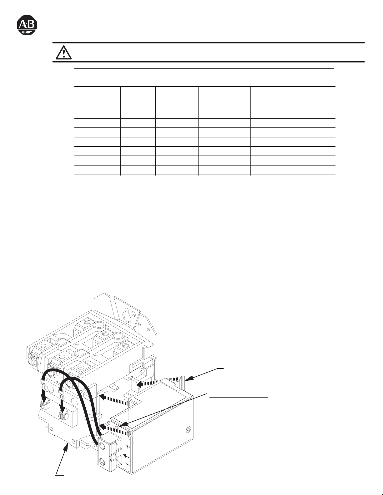
Installation
1) Remove Coil Cover and all control wires.
2) Pull out coil and yoke assembly.
3) Install "Special" Coil from Bulletin 599 Kit.
4) Re-install coil cover and tighten screws to 10 - 16 lb-in.
5) Align Coil Controller so that (2) tabs insert into the underside of coil cover.
6) Push side of coil controller until clips snap into place.
7) Insert the (2) wires into Special Coil terminals and tighten to 8 -10 Lb-In.
8) Connect control power from adequate DC power source (e.g. Bulletin 1606) to Coil Controller.
5.6 A
8.1 A
16.4 A
1.8 ... 0.9 A
2.4 ... 1.2 A
3.7 ... 1.9 A
Coil Cover
DC
VOLTAGE
INPUT
Clips
LED Status Indication
Solid Green - Sufficient voltage for contacts to close.
Solid Yellow - Voltage is too low to attempt contact closing.
Flashing Yellow (once every second) - Controller has an
over-temperature condition and is not operative during this
condition.
No Color (LED Off) - Polarity is reversed - reverse wires.
Page 2
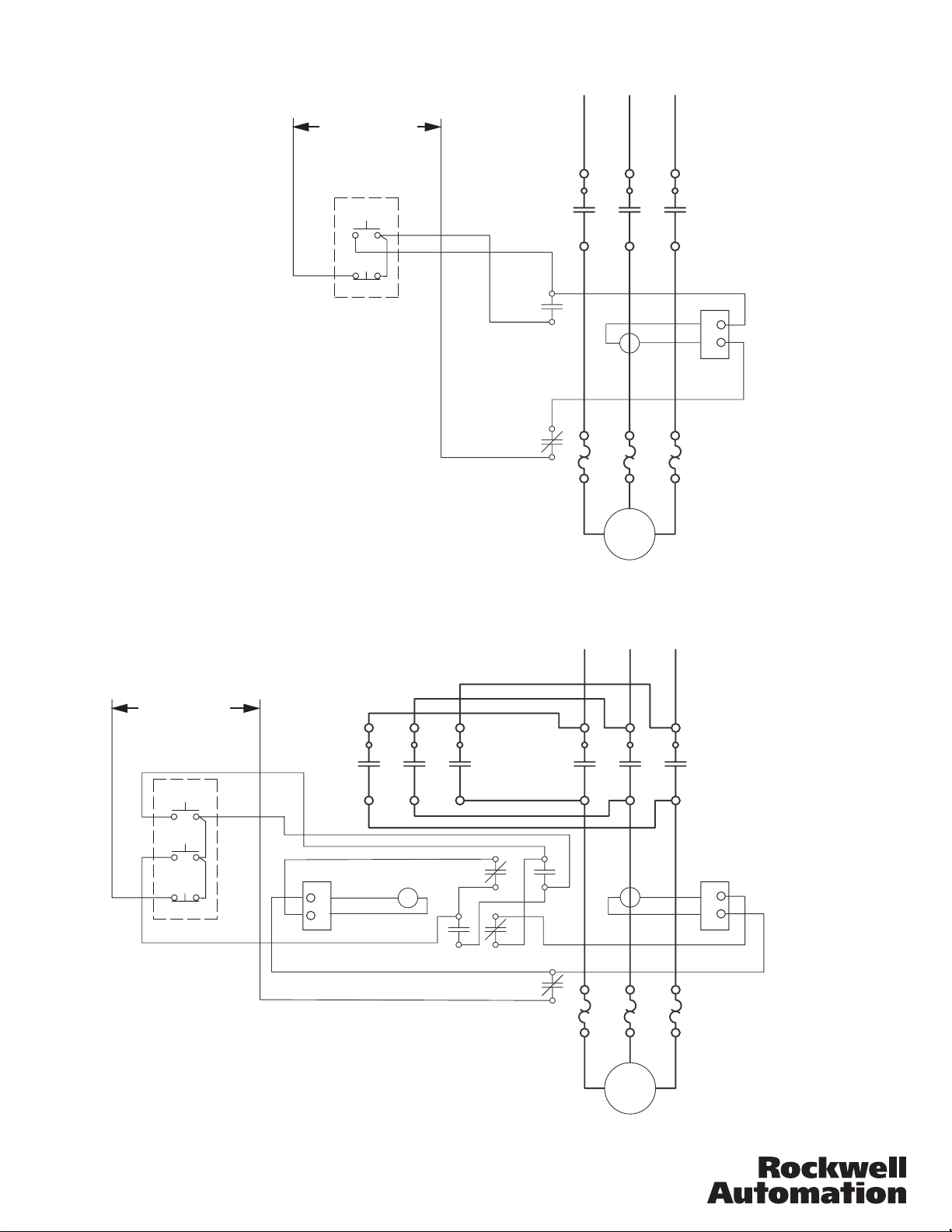
Bulletin 509 with DC Coil Controller
+
Separate DC Control
START
STOP
-
L1
3
2
Motor
L3L2
+
-
T3T2T1
Bulletin 505 with DC Coil Controllers
+
Separate DC Control
FOR
REV
STOP
-
-
+
Rev.
L1
7
5
5
6
3
F
For.
2
L3L2
+
-
R
4
3
T3T2T1
42052-124-01 (2)
Printed in U.S.A.
Motor
 Loading...