

Page 1
Hinge - Latch Kit Installation Instructions
(Cat 598-NHL22M)
ATTENTION: To prevent electrical shock, disconnect from power source before installing or servicing.
This accessory kit, when properly installed, will provide UL Type 3R, 4/4X, 12 and 13 protection for the enclosures listed in the table.
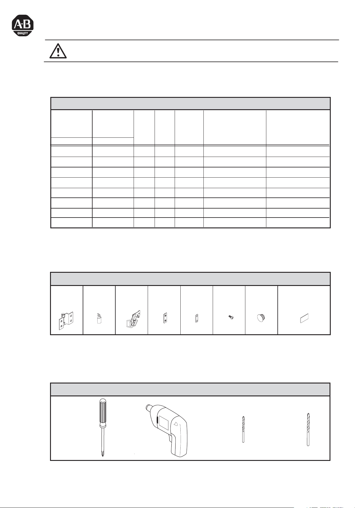
Bulletin 598 Enclosure Kits
Enclosure with
Clear Cover
Cat No. Cat No.
598-BS885C
598-BS1187C
598-BS1587C
598-BS11115C
598-BS13115C
598-BS15117C
598-BS22115C
598-BS22157C
Hinges
Qty. 2
Enclosure with
Opaque Cover
598-BS1187
598-BS1587
598-BS11115
598-BS13115
598-BS15117
598-BS22115
598-BS22157
Latch
Hook
Qty. 2
598-BS885
Length
7 - 1/2
(in.)
11
15
11
13
15
22
22
Width
(in.)
7 - 1/2
7 - 1/2
7 - 1/2
11
11
11
11
15
Number of
Kits
Required
Each Enclosure Kit Contains
Latches
Qty. 2
Threaded
Plates
Qty. 8
1
1
1
1
1
1
2
2
Gaskets
Qty. 16
Location of
Hinges from Short Sides
of Enclosure (in.)
2
2 - 1/4
3 - 1/4
2 - 1/4
2 - 1/2
3 - 1/4
2-1/2, 9
2-1/2, 9
Screws
M4 or #8
Qty. 16
Plugs
Qty. 4
Location of
Latches from Short Sides
of Enclosure (in.)
2
2 - 1/4
3 - 1/4
2 - 1/4
2 - 1/2
3 - 1/4
2-1/2, 9
2-1/2, 9
Latch Release
Instruction Label
Qty. 1
#2 Phillips
or
Posidrive
Screwdriver
Electric
Drill
Tools required
1/16"
Drill Bit
for
Pilot Hole
5/32" or M4
Drill Bit
for
Final Hole
Page 2
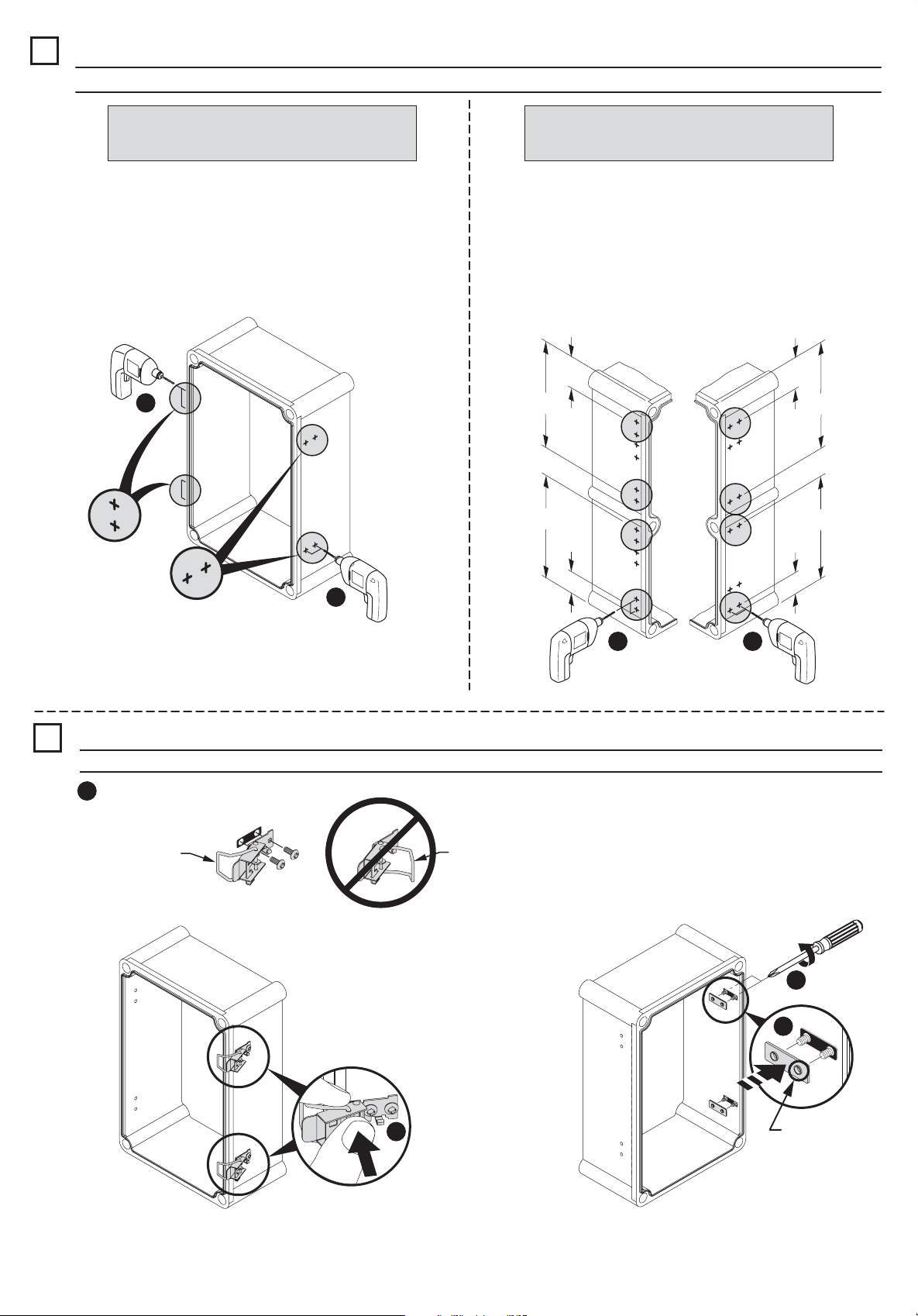
Drill Holes in Base
1
IMPORTANT: Drill bit diameter to not exceed .161 in (4.1 mm). Do not drill into the short sides of the enclosure.
7-1/2" thru 15" Long Enclosures
(598-BS885_ -BS1187_, -BS1587_, -BS11115_,
-BS13115_, -BS15117_)
Note: Drill 1/16" pilot hole first, then drill 5/32" or 4mm
hole for two latches and two hinges.
1
Hinge Side
Latch Side
22" Long Enclosures
(598-BS22115_, -BS22157_)
Note: Drill 1/16" pilot hole first, then drill 5/32" or 4mm
hole for four latches and four hinges in locations as
circled in diagram.
Hinge Side Latch Side
2-1/2 in.
2-1/2 in.
9 in.
9 in.
9 in.
9 in.
2
Latch Installation
2
IMPORTANT: Each latch assembly must have one gasket installed on each side of enclosure wall.
Preassemble latch, screws and gasket
1
Correct position
of wire
Incorrect position
of wire
2-1/2 in.
2-1/2 in.
21
6 - 12 lb-in
4
3
2
(2)
Extruded
side facing
away from
gasket
Page 3

Hinge Installation
3
IMPORTANT: Each hinge assembly must have one gasket installed on each side of enclosure wall.
Preassemble hinge, screws and gasket
1
4
6 - 12 lb-in
2
Remove Captive Plastic Screws (If Present)
4
from Cover
Drill Holes in Cover
5
IMPORTANT: Drill bit diameter to not exceed .161 in (4.1 mm). Do not drill into the short sidess of the enclosure.
3
Extruded
side facing
away from
gasket
7-1/2" thru 15" Long Enclosures
(598-BS885_ -BS1187_, -BS1587_, -BS11115_,
-BS13115_, -BS15117_)
Note: Drill 1/16" pilot hole first, then drill 5/32" or
4mm hole for two latch hooks and two hinges.
1
2
2
(3)
22" Long Enclosures
(598-BS22115_, -BS22157_)
Note: Drill 1/16" pilot hole first, then drill 5/32" or 4mm hole
for four latch hooks and four hinges in locations as circled in
diagram.
Latch Hook
Side
2-1/2 in.
9 in.
9 in.
2-1/2 in.
2-1/2
9 in.
9 in.
2-1/2 in.
Hinge Side
in.
21
Page 4

Latch Hook Installation
6
IMPORTANT: Each latch hook must have one gasket installed on each side of enclosure wall.
Preassemble latch hook, screws and gasket
1
IMPORTANT: If the hook does not lie flat, install on other side of cover.
Hook must lie flat against cover Hook can not be tilted after installation
3
6 - 12 lb-in
2
Cover Installation
7
IMPORTANT: Each hinge assembly must have one gasket installed on each side of enclosure wall.
1
4
Extruded side
facing
away from
gasket
2
Extruded
side facing
away from
gasket
42052-163-01 (1)
Printed in Korea
3
6 - 12 lb-in
Click
5
4
Click
Latch Release Label
6
 Loading...