

Page 1
(A)
(A)
(A)
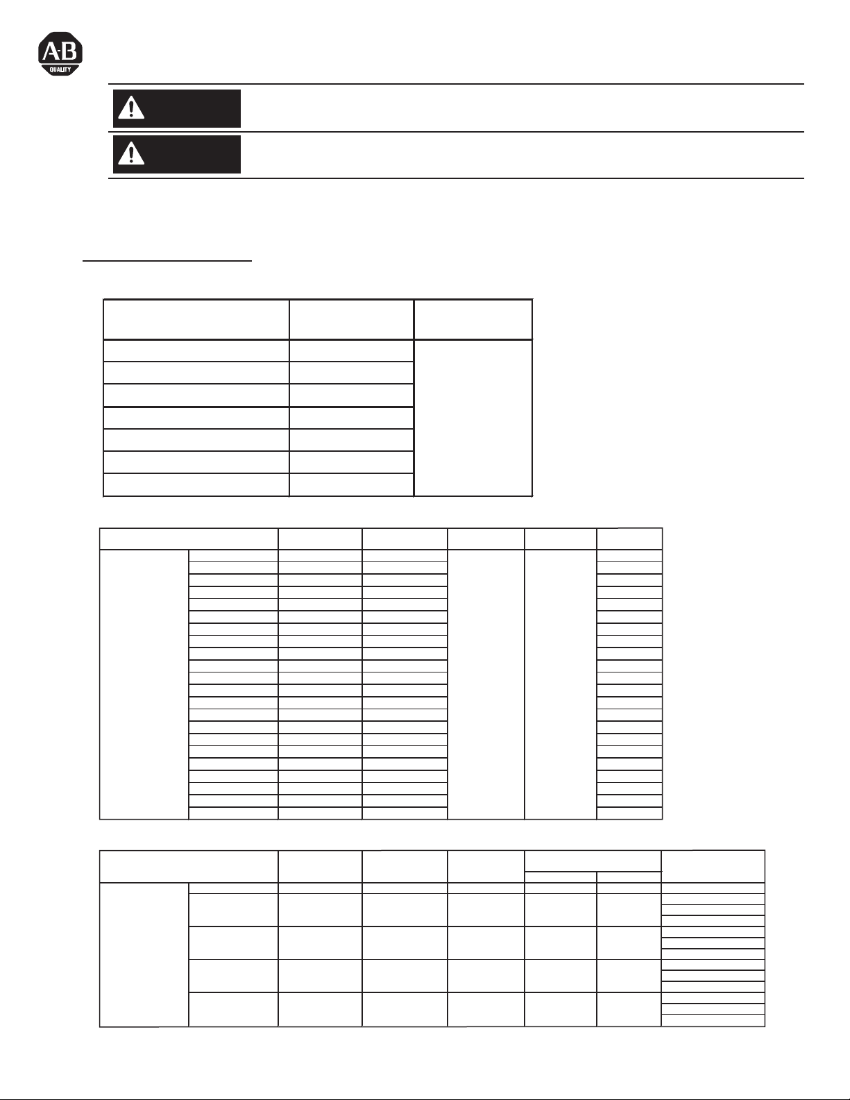
Bulletin 193 / 592 MCS-E3 Electronic Overload Relay
Short Circuit Ratings
WARNING
WARNING
To prevent electrical shock, disconnect from power source before installing or servicing.
Select the motor branch circuit protection that complies with the national Electrical Code and any other
governing regional and local codes.
The MCS-E3 overload relay is suitable for use on circuits capable of delivering not more than the RMS symmetrical amperes listed in
the following tables:
Short Circuit Ratings
Table 1 Standard Fault Short Circuit Ratings per UL508 and CSA 22.2 No.14
MCS-E3 Cat. No. Max. available fault
current (A)
193-EC_B, 592-EC_T 5,000
193-EC_D, 592-EC_C 5,000
193-EC_E, 592-EC_D 10,000
193-EC_F 10,000
193-EC_G 18,000
193-EC_H 42,000
193-EC_Z 5,000
Max. voltage (V)
600
Table 2 High fault short circuit ratings per UL 508 and CSA 22.2 no. 14 with 100-C and 100-D contactors
MCS-E3 Cat. No. Contactor Cat. No. Max. Starter FLC (A) Max available fault
193-EC1
193-EC2
193-EC3
193-EC4
193-EC5
Table 3 High fault short circuit ratings per UL 508 and CSA 22.2 no. 14 with NEMA contactors
MCS-E3 NEMA Cat. No. Contactor Size
592-EC1
592-EC2
592-EC3
592-EC5
PN-17757
DIR 10000010791 (Version 03)
Printed in U.S.A.
_B
_B
_B
_B
_D
_D
_D
_E
_E
_E
FF, ZZ
FF, ZZ
FF, ZZ
GF, ZZ
GG, ZZ
GG, ZZ
GG, ZZ
HG, ZZ
HG, ZZ
HG, ZZ
JG, ZZ
JG, ZZ
_T
_C
_C
_C
_D
100-C09 9 20
100-C12 12 20
100-C16 16 30
100-C23 23 30
100-C30 30 50
100-C37 37 50
100-C43 43 70
100-C60 60 80
100-C72 72 100
100-C85 85 150
100-D95 95 100,000 600 200
100-D110 110 200
100-D140 140 250
100-D180 180 300
100-D210 210 400
100-D250 250 400
100-D300 300 500
100-D210 210 400
100-D250 250 400
100-D300 300 500
100-D300 300 500
100-D42
0 420 600
Max available fault
current
00 100,000 600 --- 20 ---
0 100,000 480 30 30 FDB 3025/LFB 3070R
1 100,000 480 30 50 FDB 3035/LFB 3070R
2 100,000 480 60 100 ---
3 100,000 480 100 200 FDB 3125/LFB 3150R
current
Max. voltage (V) Circuit breaker / Limiter
240 30 30 FDB 3025/LFB 3070R
600 30 30 --240 60 100 FDB 3050/LFB 3070R
600 30 50 --240 100 200 FDB 3100/LFB 3150R
600 60 100 --240 200 350 FDB 3150/LFB 3150R
600 100 200 FDB 3100/LFB 3150R
Max. voltage (V) Max Class J or
Max UL fuse (A)
RJ
CC fuse
Page 2
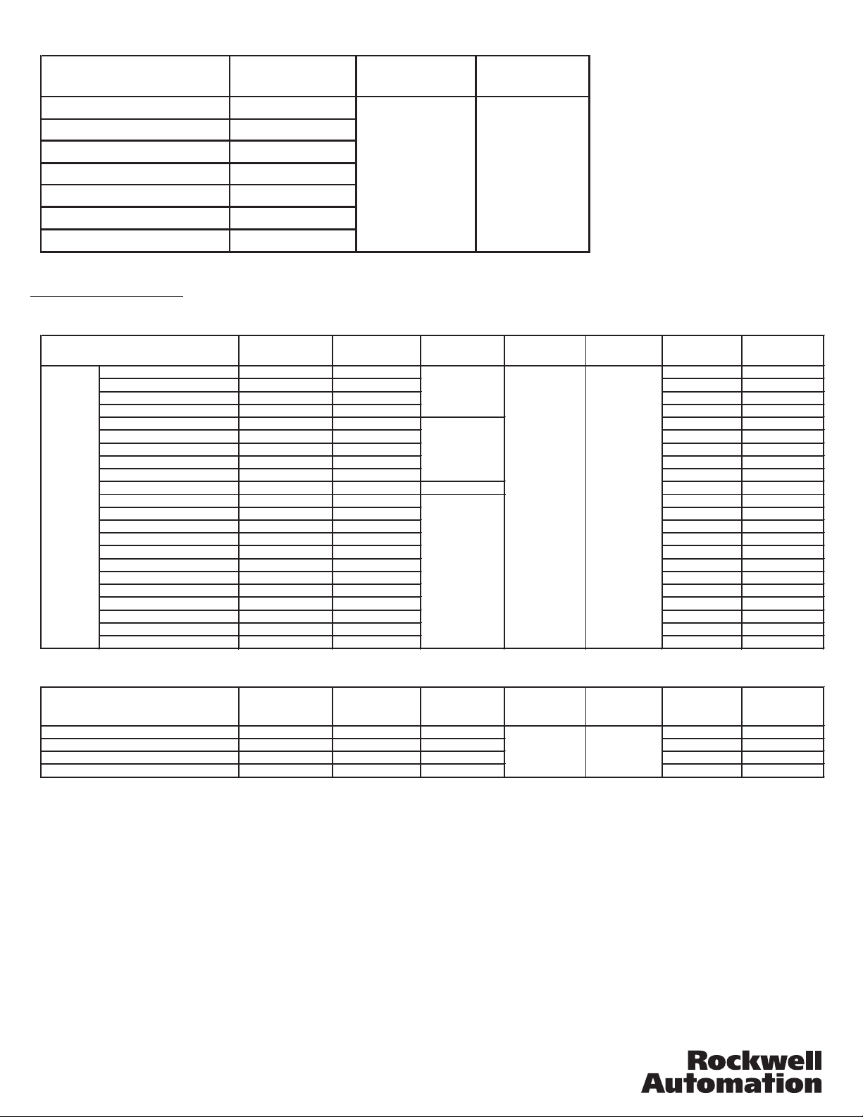
Table 4 IEC Short Circuit Ratings per EN60947-4-1
_
_
_
_
_
_
_
_
MCS-E3 Cat. No. Prospective S.C.
current, Ir (A)
Conditional S.C.
current, Iq (A)
Max. voltage (V)
193-EC_B, 592-EC_T 1,000
193-EC_D, 592-EC_C 3,000
193-EC_E, 592-EC_D 5,000
193-EC_F
193-EC_G
193-EC_H
193-EC_Z
10,000
18,000
30,000
1,000
100,000 690
Fuse Coordination
Table 5 IEC Type 1 and Type II Fuse Coordination with Bul. 100-C and 100-D contactors per EN60947-4-1
193-EC1
193-EC2
193-EC3
193-EC4
193-EC5
MCS-E3 Cat. No.
B
B
B
B
_D 100-C30 30 50 50
_D 100-C37 37 50 50
_D 100-C43 43 70 70
_E 100-C60 60 80 80
_E 100-C72 72 100 100
_E 100-C85 85
FF, ZZ 100-D95 95 200 200
FF, ZZ 100-D110 110 200 200
FF, ZZ 100-D140 140 250 250
GF, ZZ 100-D180 180 300 300
GG, ZZ 100-D210 210 400 400
GG, ZZ 100-D250 250 400 400
GG, ZZ 100-D300 300 500 500
HG, ZZ 100-D210 210 400 400
HG, ZZ 100-D250 250 400 400
HG, ZZ 100-D300 300 500 500
JG, ZZ 100-D300 300 500 500
JG, ZZ 100-D420 420 600 600
Contactor Cat. No. Max. starter FLC
(A)
100-C09 9 20 15
100-C12 12 20 20
100-C16 16 30 30
100-C23 23 40 40
Prospective S.C.
current, Ir (A)
1,000
3,000
5,000
10,000
Conditional S.C.
current, Iq (A)
100,000 600
Max. voltage
(V)
Type I with
Class J fuse (A)
Type II with
Class J fuse (A)
150 150
Table 6 Type 1 and Type II Fuse Coordination with NEMA Contactors
MCS-E3 Cat. No.
T
592-EC
C
592-EC
592-EC
C
D
592-EC
PN-17757
DIR 10000010791 (Version 03)
Printed in U.S.A.
Contactor Size
00 9 1,000 20 20
0, 1 18, 27
245
390
Max. starter FLC
(A)
Prospective S.C.
current, Ir (A)
3,000
3,000
5,000
Conditional S.C.
current, Iq (A)
100,000 600
Max. voltage
(V)
Type I with
Class J fuse (A)
30 30
60 60
200 200
Type II with
Class J fuse (A)
 Loading...