

Page 1
Product Information
Bulletin 193 / 592 E3 and E3 Plus Solid State Overload Relay
(Cat 193-EC_ _ _; 592-EC_ _ _)
WARNING: To prevent electrical shock, disconnect from power source before installing or servicing. Follow NFPA 70E requirements. Install in suitable enclosure. Keep free from contaminants.
Installation, adjustments, putting into service, use, assembly, disassembly, and maintenance shall be carried out by suitably trained personnel in accordance with applicable code of practice. In case of malfunction or
damage, no attempts at repair should be made. The product should be returned to the manufacturer for repair. Do not dismantle the product.
ATTENTION: Do not install, congure, operate or maintain this product until you have read the product documentation and the documents in the Additional Resources section for installing, conguring, operating or maintaining
equipment. To get the product documentation go to http://www.rockwellautomation.com/literature or contact your local sales oce or Rockwell Automation representative.
ATTENTION: Ne pas installer, congurer, exploiter ou maintenir ce produit tant que vous n’avez pas lu sa documentation et les documents de la rubrique Documents connexes pour l’installation, la conguration, l’exploitation et la
maintenance de l’équipement. Pour obtenir de la documentation, rendez-vous sur le site http://www.rockwellautomation.com/literature ou contactez votre agence commerciale Rockwell Automation locale ou son représentant.
ACHTUNG: Für die Installation, Konguration, den Betrieb und die Wartung dieses Produkt lesen Sie sich bitte zunächst die Produktdokumentation sowie die Dokumente im Abschnitt „Weitere Informationen“ durch. Die
entsprechende Produktdokumentation nden Sie unter http://www.rockwellautomation.com/literature oder kontaktieren Sie Ihr lokales Vertriebsbüro bzw. einen Rockwell Automation-Mitarbeiter.
ATENCIÓN: No instale, congure, opere ni mantenga este producto hasta que haya leído la documentación del producto y los documentos en la sección Recursos adicionales para la instalación, conguración, operación o
mantenimiento de equipo. Para conseguir la documentación, diríjase a http://www.rockwellautomation.com/literature o póngase en contacto con su ocina regional de ventas o representante de Rockwell Automation.
ATENÇÃO: Não instale, congure, opere ou mantenha este produto até que você leia a documentação do produto e os documentos na seção Recursos adicionais para a instalação, conguração, operação ou manutenção do
equipamento. Para conseguir a documentação, visite http://www.rockwellautomation.com/literature ou entre em contato con seu escritório de vendas regional ou representante da Rockwell Automation.
ATTENZIONE: Non installare, congurare, attivare o riparare questo prodotto senza avere prima letto la relativa documentazione nonchè i documenti indicati nella sezione Ulteriori Risore riguardanti l’installazione, la congurazione,
l’attivazione o la riparazione dell’apparecchiatura. Per la documentazione sul prodotto visitare il sito http://www.rockwellautomation.com/literature o contattare l’ucio vendite o il rappresentate Rockwell Automation di zona.
Additional Resources:
1) Go to http://www.rockwellautomation.com/literature; 2) Go to Search, select Publication Number. Type in: 193-UM002 or 193-QR003
Terminal Designations
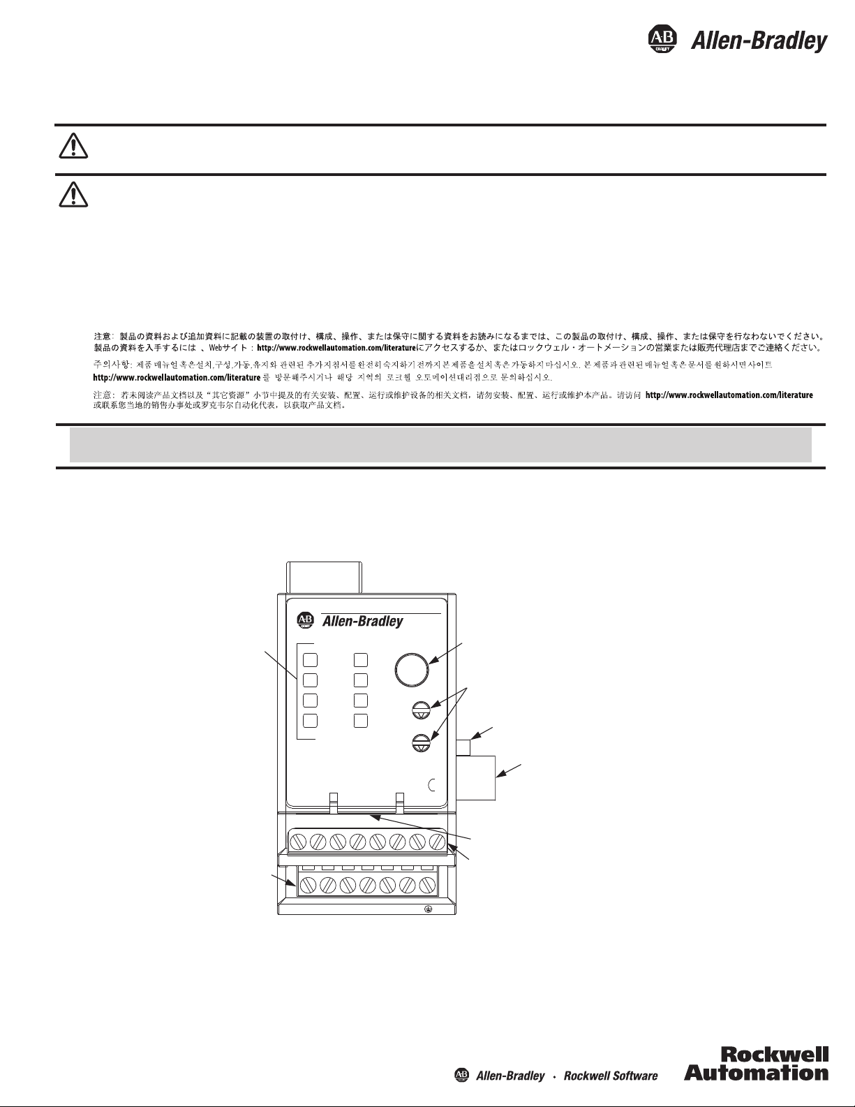
Figure 1 - E3 and E3 Plus Feature Overview
LED Status
Indicators
Input
Terminals
E3 PLUS
TEST/
RESET
NETWORK
STATUS
OUT A
IN 1
IN 2
D S/N
FRN
TRIP
WARN
IN 4
1AOXXXXX
4.XXX
OUT B
IN 3
MSD
LSD
XXX
SER
13 14 23 24 95 96 1T1 1T2
1 2 3 4 5 6
Test/Reset Button
Node Address Switches
(series B and later)
Voltage Input Module
Connection
(193/592 EC5 only)
S1
Ground Fault
Sensor Input
S2
DeviceNet Port
Output & PTC Terminals
NOTE: On model EC5 devices,
terminals 1T1 and 1T2 are
marked 7 and 8, respectively.
Page 2
2
Bulletin 193 / 592 E3 and E3 Plus Solid State Overload Relay
Control Terminals
The following table denes the E3 Overload Relay control terminal
designations.
Table 1 - Control Terminal Designation
Ter m in al
Designation
1 IN 1 General-purpose sinking input number 1
2 IN 2 General-purpose sinking input number 2
3 IN 3 General-purpose sinking input number 3
4 IN 4 General-purpose sinking input number 4
5V+
6V+
7 IN 5 General-purpose sinking input number 5
8 IN 6 General-purpose sinking input number 6
13/14 OUT A Output A
23/24 OUT B Output B
95/96 Trip Relay Trip Relay
1T1/1T2 PTC Thermistor (PTC) input
S1/S2 -- External ground fault sensor input
Features are available only with the E3 Plus Overload Relay (cat. nos. 193/592-EC2 and
193/592-EC3).
Available only on cat. nos. 193/592-EC5_ _.
An earth ground connection to this terminal will assist in obtaining compliance with
electromagnetic compatibility requirements.
The use of shielded cable is recommended for the positive PTC thermistor circuit to assist
in obtaining compliance with electromagnetic compatibility requirements.
Available only on cat. nos. 193/592-EC3_ _ and 193/592-EC4_ _.
Reference Description
+24V DC supply for inputs
End Earth Ground
DeviceNet Terminals
The following table denes the DeviceNet connector terminal
designations.
Table 2 - DeviceNet Terminal Designation
Terminal Signal Function Color
BlackCommonV-1
CAN_L2
Signal High
BlueSignal Low
Non-insulatedShieldDrain3
WhiteCAN_H4
RedPower SupplyV+5
Grounding
The following grounding recommendations are provided to ensure electromagnetic compatibility compliance during installation:
· The earth ground terminal of the E3 Overload Relay shall be connected to a solid earth ground via a low-impedance connection.
· Installations employing an external ground fault sensor shall ground the cable shield at the sensor with no connection made at the E3 Plus
Overload Relay.
· The PTC thermistor cable shield shall be grounded at the E3 Plus Overload Relay with no connection made at the opposite end.
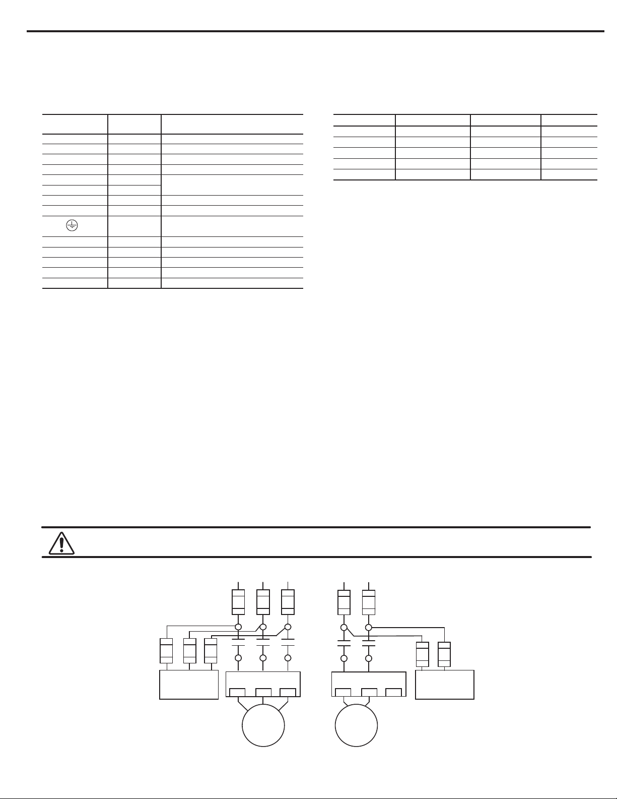
Wiring Diagrams
WARNING: When working on energized circuits, do not rely on the voltage and current information provided by the E3 and E3 Plus for personal safety. Always
use a portable voltage or current measurement device and measure the signal locally.
Single-Phase Full-VoltageThree-Phase Direct-On-Line
Figure 2 - Three-Phase D.O.L &
Single-Phase Wiring Diagrams
Voltage Input Module
(For 193/592-EC5 only)
L2 L3L1
T2
T1
T3
S.C.P.D.
L1 L2L1 L3L2
E3/E3 PlusE3/E3 Plus
2/T1 6/T3
4/T22/T1 6/T34/T2
T2
T1
MM
L2L1
Voltage Input Module
(For 193/592-EC5 only)
Publication 193-IN055B-EN-P - August 2013 PN-154492 DIR 10000279804 (Version 01)
Page 3

Short Circuit Ratings
3Bulletin 193 / 592 E3 and E3 Plus Solid State Overload Relay
Table 3 - Standard Fault Short-Circuit Ratings
per UL 508 and CSA 22.2, No. 14
Cat. No.
193-EC_D, 592EC_C
193-EC_E, 592EC_D
193-EC_F
193-EC_G
193-EC_H
193-EC_Z
Max. Available
Fault Current [A]
5000193-EC_B, 592EC_T
5000
10000
10000
18000
42000
5000
Max.
Voltage [V]
600
Table 5 - IEC Short-Circuit Ratings per EN60947-4-1
Cat. No.
193-EC_B, 592EC_T
193-EC_D, 592EC_C
193-EC_E, 592EC_D
193-EC_F
193-EC_G
193-EC_H
193-EC_Z
Prospective
Short-Circuit
Current I
1000
3000
5000
10000
18000
30000
1000
r
[A]
Conditional
Short-Circuit
Current Iq [A]
100000
Max.
Voltage [V]
690
Table 4 - High Fault Short-Circuit Ratings per UL 508 and CSA 22.2,
No. 14 with Bulletin 100-C and 100-D contactors
_B
_D
_E
FF, ZZ
FF, ZZ
FF, ZZ
GG, ZZ
GG, ZZ
HG, ZZ
JG, ZZ
Contactor
100-C09
100-C12
100-C16
100-C23
100-C30
100-C37
100-C43
100-C60
100-C72
100-C85
100-D95
100-D110
100-D140
100-D180
100-D210
100-D250
100-D300
100-D210
100-D250
100-D300
100-D300
100-D420
Max. Starter
FLC [A]
9
12
16
23
30
37
43
60
72
85
95
110
140
180
210
250
300
210
250
300
300
420
Fault Current [A]
100000 600
Max.
Voltage [V]
Max. Class J or
CC Fuse [A]
Cat. No Max. Available
193-EC1
193-EC2
193-EC3
193-EC4
193-EC5
20
20
30
30
50
50
70
80
100
150
200
200
250
300
400
400
500
400
400
500
500
600
Table 6 - High Fault Short-Circuit Ratings per UL 508 and CSA 22.2, No. 14
with NEMA contactors
Cat. No.
592-EC1
592-EC2
592-EC3
592-EC5
Contactor
Size
_T
_C
_C
_C
_D
Max. Available
Fault Current [A]
00 100000 600
0 100000
1 100000
2 100000
3 100000
Max.
Voltage [V]
240 30 FDB 3025/LFB3070R30
480 30 FDB 3025/LFB3070R30
600 30 ----30
240 60 FDB 3050/LFB3035R100
480 30 FDB 3050/LFB3035R
600 30 ----50
240 100 200
480 60 ----100
600 60 ----100
240 200 350 FDB 3150/LFB3150R
480 100 200 FDB 3125/LFB3150R
600 100 200 FDB 3100/LFB3150R
Max. UL Fuse [A]
RJ
---- ----20
50
Circuit Breaker/
Limiter
FDB 3100/LFB3150R
Publication 193-IN055B-EN-P - August 2013 PN-154492 DIR 10000279804 (Version 00)
Page 4

Fuse Coordination
Table 7 - IEC Type 1 and Type II Fuse Coordination with Bulletin 100-C and 100-D Contactors per EN60947-4-1
Cat. No
193-EC1
193-EC2
193-EC3
193-EC4
193-EC5
Contactor
100-C09
100-C12
_B 1000
100-C16
100-C23
100-C30
_D
100-C37
100-C43
100-C60
_E
100-C72
100-C85
FF, ZZ
FF, ZZ
FF, ZZ
GG, ZZ
GG, ZZ
HG, ZZ
JG, ZZ
100-D95
100-D110
100-D140
100-D180
100-D210
100-D250
100-D300
100-D210
100-D250
100-D300
100-D300
100-D420
Max. Starter
FLC [A]
9
12
16
23
30
37
43
60
72
85
95
110
140
180
210
250
300
210
250
300
300
420
Prospective
Short-Circuit
Current Ir [A]
3000
5000
10000
Conditional
Short-Circuit
Current I
[A]
q
100000 600
Max.
Voltage [V]
Type I
with Class J
Fuse [A]
20
20
30
40
50
50
70
80
100
150
200
200
250
300
400
400
500
400
400
500
500
600
Type II
with Class J
Fuse [A]
15
20
30
40
50
50
70
80
100
150
200
200
250
300
400
400
500
400
400
500
500
600
Table 8 - Type 1 and Type II Fuse Coordination with NEMA Contactors
Cat. No Conditional
592-EC_T 1000
592-EC_C
592-EC_D
Contactor
Size
00
0,1592-EC_C
2
3
Max. Starter
FLC [A]
18, 27
45
90
9
Prospective
Short-Circuit
Current Ir [A]
3000
3000
5000
Short-Circuit
Current I
q
100000
[A]
Max.
Voltage [V]
600
Type I
with Class J
Fuse [A]
20
30
60
200
Type II
with Class J
Fuse [A]
20
30
60
200
Table 9 - Short circuit ratings, using 140U D Frame circuit breakers, per UL508 and CSA 22.2 No. 14
Overload Relay
Cat. No.
-EC1, -EC2, -EC3,
193
-EC4, -EC5
-EC1, -EC2, -EC3,
193
-EC4, -EC5
-EC1, -EC2, -EC3,
193
-EC4, -EC5
Allen-Bradley, Rockwell Software, and Rockwell Automation are trademarks of Rockwell Automation, Inc.
Trademarks not belonging to Rockwell Automation are property of their respective companies.
Overload Relay
FLA Suxes
PB, AB, BB, CB
PB, AB, BB, CB
PB, AB, BB, CB
Contactor
100-C09,
100-C12,
100-C16
100-C23
100-C09,
100-C12,
100-C16
100-C23
100-C09,
100-C12,
100-C16
100-C23
Overload Relay
FLA Suxes
9
12
16
23
9
12
16
23
9
12
16
23
Max.
Available Fault
Current (A)
65,000
35,000
5,000
Max.
Voltage (V)
480Y / 277V
600Y / 347V
600Y / 347V
Max.
Circuit Breaker
140U-D6D3-C30
(30 Amps)
140U-D6D3-C30
(30 Amps)
140U-D6D3-C30
(30 Amps)
Publication 193-IN055B-EN-P - August 2013
Copyright © 2013 Rockwell Automation, Inc. All Rights Reserved. Printed in USA.
DIR 10000279804 (Version 01)
PN-154492
 Loading...