

Page 1

User Manual
E300 Electronic Overload Relay
Bul. 193/592
Page 2

Important User Information
IMPORTANT
Read this document and the documents listed in the additional resources section about installation, configuration, and
operation of this equipment before you install, configure, operate, or maintain this product. Users are required to
familiarize themselves with installation and wiring instructions in addition to requirements of all applicable codes, laws,
and standards.
Activities including installation, adjustments, putting into service, use, assembly, disassembly, and maintenance are required
to be carried out by suitably trained personnel in accordance with applicable code of practice.
If this equipment is used in a manner not specified by the manufacturer, the protection provided by the equipment may be
impaired.
In no event will Rockwell Automation, Inc. be responsible or liable for indirect or consequential damages resulting from the
use or application of this equipment.
The examples and diagrams in this manual are included solely for illustrative purposes. Because of the many variables and
requirements associated with any particular installation, Rockwell Automation, Inc. cannot assume responsibility or
liability for actual use based on the examples and diagrams.
No patent liability is assumed by Rockwell Automation, Inc. with respect to use of information, circuits, equipment, or
software described in this manual.
Reproduction of the contents of this manual, in whole or in part, without written permission of Rockwell Automation,
Inc., is prohibited.
Throughout this manual, when necessary, we use notes to make you aware of safety considerations.
WARNING: Identifies information about practices or circumstances that can cause an explosion in a hazardous environment,
which may lead to personal injury or death, property damage, or economic loss.
ATTENTION: Identifies information about practices or circumstances that can lead to personal injury or death, property
damage, or economic loss. Attentions help you identify a hazard, avoid a hazard, and recognize the consequence.
Identifies information that is critical for successful application and understanding of the product.
Labels may also be on or inside the equipment to provide specific precautions.
SHOCK HAZARD: Labels may be on or inside the equipment, for example, a drive or motor, to alert people that dangerous
voltage may be present.
BURN HAZARD: Labels may be on or inside the equipment, for example, a drive or motor, to alert people that surfaces may
reach dangerous temperatures.
ARC FLASH HAZARD: Labels may be on or inside the equipment, for example, a motor control center, to alert people to
potential Arc Flash. Arc Flash will cause severe injury or death. Wear proper Personal Protective Equipment (PPE). Follow ALL
Regulatory requirements for safe work practices and for Personal Protective Equipment (PPE).
Allen-Bradley, Rockwell Software, and Rockwell Automation are trademarks of Rockwell Automation, Inc.
Trademarks not belonging to Rockwell Automation are property of their respective companies.
Page 3

Product Overview
Table of Contents
Chapter 1
Overview . . . . . . . . . . . . . . . . . . . . . . . . . . . . . . . . . . . . . . . . . . . . . . . . . . . . . . . . 11
Modular Design . . . . . . . . . . . . . . . . . . . . . . . . . . . . . . . . . . . . . . . . . . . . . . 11
Communication Options . . . . . . . . . . . . . . . . . . . . . . . . . . . . . . . . . . . . . 11
Diagnostic Information . . . . . . . . . . . . . . . . . . . . . . . . . . . . . . . . . . . . . . . 12
Simplified Wiring . . . . . . . . . . . . . . . . . . . . . . . . . . . . . . . . . . . . . . . . . . . . 12
Catalog Number Explanation . . . . . . . . . . . . . . . . . . . . . . . . . . . . . . . . . . . . . 13
Sensing Module . . . . . . . . . . . . . . . . . . . . . . . . . . . . . . . . . . . . . . . . . . . . . . 13
Control Module. . . . . . . . . . . . . . . . . . . . . . . . . . . . . . . . . . . . . . . . . . . . . . 13
Communication Module. . . . . . . . . . . . . . . . . . . . . . . . . . . . . . . . . . . . . . 13
Digital Expansion Module . . . . . . . . . . . . . . . . . . . . . . . . . . . . . . . . . . . . 14
Analog Expansion Module . . . . . . . . . . . . . . . . . . . . . . . . . . . . . . . . . . . . 14
Operator Station . . . . . . . . . . . . . . . . . . . . . . . . . . . . . . . . . . . . . . . . . . . . . 14
Power Supply . . . . . . . . . . . . . . . . . . . . . . . . . . . . . . . . . . . . . . . . . . . . . . . . 14
Module Description. . . . . . . . . . . . . . . . . . . . . . . . . . . . . . . . . . . . . . . . . . . . . . 15
Sensing Module . . . . . . . . . . . . . . . . . . . . . . . . . . . . . . . . . . . . . . . . . . . . . . 15
Control Module. . . . . . . . . . . . . . . . . . . . . . . . . . . . . . . . . . . . . . . . . . . . . . 16
Communication Module. . . . . . . . . . . . . . . . . . . . . . . . . . . . . . . . . . . . . . 16
Optional Add-On Modules . . . . . . . . . . . . . . . . . . . . . . . . . . . . . . . . . . . . . . . 17
Optional Expansion I/O . . . . . . . . . . . . . . . . . . . . . . . . . . . . . . . . . . . . . . 17
Optional Operator Station . . . . . . . . . . . . . . . . . . . . . . . . . . . . . . . . . . . . 18
Optional Expansion Bus Power Supply. . . . . . . . . . . . . . . . . . . . . . . . . 18
Protection Features. . . . . . . . . . . . . . . . . . . . . . . . . . . . . . . . . . . . . . . . . . . . . . . 19
Standard Current-Based Protection. . . . . . . . . . . . . . . . . . . . . . . . . . . . 19
Ground Fault Current Based Protection. . . . . . . . . . . . . . . . . . . . . . . . 19
Voltage and Power Based Protection . . . . . . . . . . . . . . . . . . . . . . . . . . . 19
Applications: . . . . . . . . . . . . . . . . . . . . . . . . . . . . . . . . . . . . . . . . . . . . . . . . . . . . 20
Installation and Wiring
Chapter 2
Introduction . . . . . . . . . . . . . . . . . . . . . . . . . . . . . . . . . . . . . . . . . . . . . . . . . . . . 21
Receiving. . . . . . . . . . . . . . . . . . . . . . . . . . . . . . . . . . . . . . . . . . . . . . . . . . . . . . . . 21
Unpacking/Inspecting . . . . . . . . . . . . . . . . . . . . . . . . . . . . . . . . . . . . . . . . . . . 21
Storing . . . . . . . . . . . . . . . . . . . . . . . . . . . . . . . . . . . . . . . . . . . . . . . . . . . . . . . . . 21
General Precautions . . . . . . . . . . . . . . . . . . . . . . . . . . . . . . . . . . . . . . . . . . . . . 22
Base Relay Assembly . . . . . . . . . . . . . . . . . . . . . . . . . . . . . . . . . . . . . . . . . . . . . 22
Control Module to Sensing Module Assembly. . . . . . . . . . . . . . . . . . . . . . 23
Communication Module to Control Module Assembly . . . . . . . . . . . . . 24
Expansion Bus Peripherals . . . . . . . . . . . . . . . . . . . . . . . . . . . . . . . . . . . . . . . . 25
Expansion Bus Digital & Analog I/O Modules and Power Supply
Installation . . . . . . . . . . . . . . . . . . . . . . . . . . . . . . . . . . . . . . . . . . . . . . . . . . . . . . 26
Expansion Bus Operator Station Installation . . . . . . . . . . . . . . . . . . . . . . . 26
Expansion Bus Network Installation. . . . . . . . . . . . . . . . . . . . . . . . . . . . . . . 26
Starter Assembly . . . . . . . . . . . . . . . . . . . . . . . . . . . . . . . . . . . . . . . . . . . . . . . . . 28
Starter Dimensions. . . . . . . . . . . . . . . . . . . . . . . . . . . . . . . . . . . . . . . . . . . . . . . 29
DIN Rail / Panel Mount Dimensions. . . . . . . . . . . . . . . . . . . . . . . . . . . . . . 31
Rockwell Automation Publication 193-UM015B-EN-P - June 2014 3
Page 4

Table of Contents
System Operation and Configuration
Expansion Bus Peripherals Dimensions. . . . . . . . . . . . . . . . . . . . . . . . . . . . . 32
Terminals. . . . . . . . . . . . . . . . . . . . . . . . . . . . . . . . . . . . . . . . . . . . . . . . . . . . . . . . 34
Sensing Module . . . . . . . . . . . . . . . . . . . . . . . . . . . . . . . . . . . . . . . . . . . . . . 34
Control Module . . . . . . . . . . . . . . . . . . . . . . . . . . . . . . . . . . . . . . . . . . . . . . 35
Expansion Digital Module. . . . . . . . . . . . . . . . . . . . . . . . . . . . . . . . . . . . . 37
Expansion Analog Module . . . . . . . . . . . . . . . . . . . . . . . . . . . . . . . . . . . . 38
Expansion Power Supply . . . . . . . . . . . . . . . . . . . . . . . . . . . . . . . . . . . . . . 40
Grounding. . . . . . . . . . . . . . . . . . . . . . . . . . . . . . . . . . . . . . . . . . . . . . . . . . . . . . . 41
Short-Circuit Ratings . . . . . . . . . . . . . . . . . . . . . . . . . . . . . . . . . . . . . . . . . . . . 41
Fuse Coordination . . . . . . . . . . . . . . . . . . . . . . . . . . . . . . . . . . . . . . . . . . . . . . . 42
Typical Motor Connections . . . . . . . . . . . . . . . . . . . . . . . . . . . . . . . . . . . . . . 43
External Line Current Transformer Application . . . . . . . . . . . . . . . . . . . . 44
Control Circuits . . . . . . . . . . . . . . . . . . . . . . . . . . . . . . . . . . . . . . . . . . . . . . . . . 48
Chapter 3
Introduction . . . . . . . . . . . . . . . . . . . . . . . . . . . . . . . . . . . . . . . . . . . . . . . . . . . . 51
Device Modes . . . . . . . . . . . . . . . . . . . . . . . . . . . . . . . . . . . . . . . . . . . . . . . . . . . . 51
Administration Mode. . . . . . . . . . . . . . . . . . . . . . . . . . . . . . . . . . . . . . . . . 51
Operation Mode. . . . . . . . . . . . . . . . . . . . . . . . . . . . . . . . . . . . . . . . . . . . . . 52
Run Mode . . . . . . . . . . . . . . . . . . . . . . . . . . . . . . . . . . . . . . . . . . . . . . . . . . . 52
Test Mode . . . . . . . . . . . . . . . . . . . . . . . . . . . . . . . . . . . . . . . . . . . . . . . . . . . 53
Invalid Configuration Mode. . . . . . . . . . . . . . . . . . . . . . . . . . . . . . . . . . . 53
Option Match . . . . . . . . . . . . . . . . . . . . . . . . . . . . . . . . . . . . . . . . . . . . . . . . . . . 54
Enable Option Match Protection Trip (Parameter 186). . . . . . . . . . 55
Enable Option Match Protection Warning (Parameter 192) . . . . . 56
Control Module Type (Parameter 221). . . . . . . . . . . . . . . . . . . . . . . . . 56
Sensing Module Type (Parameter 222) . . . . . . . . . . . . . . . . . . . . . . . . . 57
Communication Module Type (Parameter 223). . . . . . . . . . . . . . . . . 57
Operator Station Type (Parameter 224) . . . . . . . . . . . . . . . . . . . . . . . . 58
Digital I/O Expansion Module 1 Type (Parameter 225) . . . . . . . . . 58
Digital I/O Expansion Module 2 Type (Parameter 226) . . . . . . . . . 59
Digital I/O Expansion Module 3 Type (Parameter 227) . . . . . . . . . 59
Digital I/O Expansion Module 4 Type (Parameter 228) . . . . . . . . . 60
Analog I/O Expansion Module 1 Type (Parameter 229) . . . . . . . . . 60
Analog I/O Expansion Module 2 Type (Parameter 230) . . . . . . . . . 61
Analog I/O Expansion Module 3 Type (Parameter 231) . . . . . . . . . 61
Analog I/O Expansion Module 4 Type (Parameter 232) . . . . . . . . . 62
Option Match Action (Parameter 233). . . . . . . . . . . . . . . . . . . . . . . . . 62
Security Policy . . . . . . . . . . . . . . . . . . . . . . . . . . . . . . . . . . . . . . . . . . . . . . . . . . . 63
Device Configuration Policy. . . . . . . . . . . . . . . . . . . . . . . . . . . . . . . . . . . 63
Device Reset Policy . . . . . . . . . . . . . . . . . . . . . . . . . . . . . . . . . . . . . . . . . . . 63
Firmware Update Policy. . . . . . . . . . . . . . . . . . . . . . . . . . . . . . . . . . . . . . . 64
Security Configuration Policy. . . . . . . . . . . . . . . . . . . . . . . . . . . . . . . . . . 64
I/O Assignments . . . . . . . . . . . . . . . . . . . . . . . . . . . . . . . . . . . . . . . . . . . . . . . . . 64
Input Pt00 Assignment (Parameter 196). . . . . . . . . . . . . . . . . . . . . . . . 64
Input Pt01 Assignment (Parameter 197). . . . . . . . . . . . . . . . . . . . . . . . 65
Input Pt02 Assignment (Parameter 198). . . . . . . . . . . . . . . . . . . . . . . . 65
4 Rockwell Automation Publication 193-UM015B-EN-P - June 2014
Page 5

Operating Modes
Table of Contents
Input Pt03 Assignment (Parameter 199) . . . . . . . . . . . . . . . . . . . . . . . 66
Input Pt04 Assignment (Parameter 200) . . . . . . . . . . . . . . . . . . . . . . . 66
Input Pt05 Assignment (Parameter 201) . . . . . . . . . . . . . . . . . . . . . . . 67
Output Pt00 Assignment (Parameter 202) . . . . . . . . . . . . . . . . . . . . . 68
Output Pt01 Assignment (Parameter 203) . . . . . . . . . . . . . . . . . . . . . 68
Output Pt02 Assignment (Parameter 204) . . . . . . . . . . . . . . . . . . . . . 69
Activate FLA2 with Output Relay (Parameter 209) . . . . . . . . . . . . . 69
Expansion Bus Fault. . . . . . . . . . . . . . . . . . . . . . . . . . . . . . . . . . . . . . . . . . . . . . 69
Expansion Bus Trip. . . . . . . . . . . . . . . . . . . . . . . . . . . . . . . . . . . . . . . . . . . 70
Expansion Bus Warning . . . . . . . . . . . . . . . . . . . . . . . . . . . . . . . . . . . . . . 71
Emergency Start . . . . . . . . . . . . . . . . . . . . . . . . . . . . . . . . . . . . . . . . . . . . . . . . . 71
Introduction to Operating Modes . . . . . . . . . . . . . . . . . . . . . . . . . . . . . . . . . 73
Chapter 4
Introduction . . . . . . . . . . . . . . . . . . . . . . . . . . . . . . . . . . . . . . . . . . . . . . . . . . . . 75
Overload (Network) . . . . . . . . . . . . . . . . . . . . . . . . . . . . . . . . . . . . . . . . . . . . . 75
Monitor (Custom) . . . . . . . . . . . . . . . . . . . . . . . . . . . . . . . . . . . . . . . . . . . . . . . 76
Protective Trip and Warning
Functions
Chapter 5
Introduction . . . . . . . . . . . . . . . . . . . . . . . . . . . . . . . . . . . . . . . . . . . . . . . . . . . . 77
Current Based Protection. . . . . . . . . . . . . . . . . . . . . . . . . . . . . . . . . . . . . . . . . 77
Overload Protection . . . . . . . . . . . . . . . . . . . . . . . . . . . . . . . . . . . . . . . . . . 80
Phase Loss Protection. . . . . . . . . . . . . . . . . . . . . . . . . . . . . . . . . . . . . . . . . 87
Ground Fault Current Protection . . . . . . . . . . . . . . . . . . . . . . . . . . . . . 89
Stall Protection. . . . . . . . . . . . . . . . . . . . . . . . . . . . . . . . . . . . . . . . . . . . . . . 96
Jam Protection . . . . . . . . . . . . . . . . . . . . . . . . . . . . . . . . . . . . . . . . . . . . . . . 98
Underload Protection . . . . . . . . . . . . . . . . . . . . . . . . . . . . . . . . . . . . . . . 101
Current Imbalance Protection. . . . . . . . . . . . . . . . . . . . . . . . . . . . . . . . 104
Line Under Current Protection . . . . . . . . . . . . . . . . . . . . . . . . . . . . . . 108
Line Over Current Protection . . . . . . . . . . . . . . . . . . . . . . . . . . . . . . . . 117
Line Loss Protection. . . . . . . . . . . . . . . . . . . . . . . . . . . . . . . . . . . . . . . . . 125
Voltage Based Protection . . . . . . . . . . . . . . . . . . . . . . . . . . . . . . . . . . . . . . . . 132
Under Voltage Protection. . . . . . . . . . . . . . . . . . . . . . . . . . . . . . . . . . . . 135
Over Voltage Protection . . . . . . . . . . . . . . . . . . . . . . . . . . . . . . . . . . . . . 138
Voltage Imbalance Protection . . . . . . . . . . . . . . . . . . . . . . . . . . . . . . . . 141
Phase Rotation Protection . . . . . . . . . . . . . . . . . . . . . . . . . . . . . . . . . . . 144
Frequency Protection . . . . . . . . . . . . . . . . . . . . . . . . . . . . . . . . . . . . . . . . 146
Power Based Protection . . . . . . . . . . . . . . . . . . . . . . . . . . . . . . . . . . . . . . . . . 152
Real Power (kW) Protection . . . . . . . . . . . . . . . . . . . . . . . . . . . . . . . . . 155
Reactive Power (kVAR) Protection . . . . . . . . . . . . . . . . . . . . . . . . . . . 162
Apparent Power (kVA) Protection. . . . . . . . . . . . . . . . . . . . . . . . . . . . 175
Power Factor Protection . . . . . . . . . . . . . . . . . . . . . . . . . . . . . . . . . . . . . 181
Control-Based Protection. . . . . . . . . . . . . . . . . . . . . . . . . . . . . . . . . . . . . . . . 194
Test Trip . . . . . . . . . . . . . . . . . . . . . . . . . . . . . . . . . . . . . . . . . . . . . . . . . . . 196
Operator Station Trip . . . . . . . . . . . . . . . . . . . . . . . . . . . . . . . . . . . . . . . 197
Remote Trip . . . . . . . . . . . . . . . . . . . . . . . . . . . . . . . . . . . . . . . . . . . . . . . . 198
Rockwell Automation Publication 193-UM015B-EN-P - June 2014 5
Page 6

Table of Contents
Start Inhibit Protection . . . . . . . . . . . . . . . . . . . . . . . . . . . . . . . . . . . . . . 199
Preventive Maintenance. . . . . . . . . . . . . . . . . . . . . . . . . . . . . . . . . . . . . . 202
Hardware Fault. . . . . . . . . . . . . . . . . . . . . . . . . . . . . . . . . . . . . . . . . . . . . . 204
Configuration Trip . . . . . . . . . . . . . . . . . . . . . . . . . . . . . . . . . . . . . . . . . . 205
Option Match. . . . . . . . . . . . . . . . . . . . . . . . . . . . . . . . . . . . . . . . . . . . . . . 205
Expansion Bus Fault . . . . . . . . . . . . . . . . . . . . . . . . . . . . . . . . . . . . . . . . . 205
Non-Volatile Storage Fault . . . . . . . . . . . . . . . . . . . . . . . . . . . . . . . . . . . 205
Test Mode Trip . . . . . . . . . . . . . . . . . . . . . . . . . . . . . . . . . . . . . . . . . . . . . 206
Chapter 6
Commands
Metering and Diagnostics
Introduction . . . . . . . . . . . . . . . . . . . . . . . . . . . . . . . . . . . . . . . . . . . . . . . . . . . 209
Trip Reset . . . . . . . . . . . . . . . . . . . . . . . . . . . . . . . . . . . . . . . . . . . . . . . . . . . . . . 209
Configuration Preset . . . . . . . . . . . . . . . . . . . . . . . . . . . . . . . . . . . . . . . . . . . . 209
Factory Defaults . . . . . . . . . . . . . . . . . . . . . . . . . . . . . . . . . . . . . . . . . . . . . 210
Clear Command . . . . . . . . . . . . . . . . . . . . . . . . . . . . . . . . . . . . . . . . . . . . . . . . 213
Clear Operating Statistics . . . . . . . . . . . . . . . . . . . . . . . . . . . . . . . . . . . . 214
Clear History Logs. . . . . . . . . . . . . . . . . . . . . . . . . . . . . . . . . . . . . . . . . . . 214
Clear %TCU. . . . . . . . . . . . . . . . . . . . . . . . . . . . . . . . . . . . . . . . . . . . . . . . 215
Clear kWh . . . . . . . . . . . . . . . . . . . . . . . . . . . . . . . . . . . . . . . . . . . . . . . . . . 215
Clear kVARh. . . . . . . . . . . . . . . . . . . . . . . . . . . . . . . . . . . . . . . . . . . . . . . . 215
Clear kVAh . . . . . . . . . . . . . . . . . . . . . . . . . . . . . . . . . . . . . . . . . . . . . . . . . 216
Clear Max kW Demand. . . . . . . . . . . . . . . . . . . . . . . . . . . . . . . . . . . . . . 216
Clear Max kVAR Demand . . . . . . . . . . . . . . . . . . . . . . . . . . . . . . . . . . . 216
Clear Max kVA Demand . . . . . . . . . . . . . . . . . . . . . . . . . . . . . . . . . . . . . 216
Clear All . . . . . . . . . . . . . . . . . . . . . . . . . . . . . . . . . . . . . . . . . . . . . . . . . . . . 216
Chapter 7
Introduction . . . . . . . . . . . . . . . . . . . . . . . . . . . . . . . . . . . . . . . . . . . . . . . . . . . . 219
Device Monitor . . . . . . . . . . . . . . . . . . . . . . . . . . . . . . . . . . . . . . . . . . . . . . . . . 219
Percent Thermal Capacity Utilized. . . . . . . . . . . . . . . . . . . . . . . . . . . . 219
Time to Trip . . . . . . . . . . . . . . . . . . . . . . . . . . . . . . . . . . . . . . . . . . . . . . . . 220
Time To Reset . . . . . . . . . . . . . . . . . . . . . . . . . . . . . . . . . . . . . . . . . . . . . . 220
Current Trip Status. . . . . . . . . . . . . . . . . . . . . . . . . . . . . . . . . . . . . . . . . . 221
Voltage Trip Status . . . . . . . . . . . . . . . . . . . . . . . . . . . . . . . . . . . . . . . . . . 222
Power Trip Status . . . . . . . . . . . . . . . . . . . . . . . . . . . . . . . . . . . . . . . . . . . 223
Control Trip Status. . . . . . . . . . . . . . . . . . . . . . . . . . . . . . . . . . . . . . . . . . 223
Current Warning Status . . . . . . . . . . . . . . . . . . . . . . . . . . . . . . . . . . . . . 224
Voltage Warning Status . . . . . . . . . . . . . . . . . . . . . . . . . . . . . . . . . . . . . . 225
Power Warning Status . . . . . . . . . . . . . . . . . . . . . . . . . . . . . . . . . . . . . . . 226
Control Warning Status. . . . . . . . . . . . . . . . . . . . . . . . . . . . . . . . . . . . . . 226
Input Status 0 . . . . . . . . . . . . . . . . . . . . . . . . . . . . . . . . . . . . . . . . . . . . . . . 227
Input Status 1 . . . . . . . . . . . . . . . . . . . . . . . . . . . . . . . . . . . . . . . . . . . . . . . 227
Output Status . . . . . . . . . . . . . . . . . . . . . . . . . . . . . . . . . . . . . . . . . . . . . . . 228
Operator Station Status . . . . . . . . . . . . . . . . . . . . . . . . . . . . . . . . . . . . . . 229
Device Status 0 . . . . . . . . . . . . . . . . . . . . . . . . . . . . . . . . . . . . . . . . . . . . . . 230
Device Status 1 . . . . . . . . . . . . . . . . . . . . . . . . . . . . . . . . . . . . . . . . . . . . . . 231
6 Rockwell Automation Publication 193-UM015B-EN-P - June 2014
Page 7

Table of Contents
Firmware Revision Number . . . . . . . . . . . . . . . . . . . . . . . . . . . . . . . . . . 231
Control Module ID . . . . . . . . . . . . . . . . . . . . . . . . . . . . . . . . . . . . . . . . . 232
Sensing Module ID . . . . . . . . . . . . . . . . . . . . . . . . . . . . . . . . . . . . . . . . . . 232
Operator Station ID . . . . . . . . . . . . . . . . . . . . . . . . . . . . . . . . . . . . . . . . . 233
Expansion Digital Module ID . . . . . . . . . . . . . . . . . . . . . . . . . . . . . . . . 233
Operating Time . . . . . . . . . . . . . . . . . . . . . . . . . . . . . . . . . . . . . . . . . . . . . 234
Starts Counter . . . . . . . . . . . . . . . . . . . . . . . . . . . . . . . . . . . . . . . . . . . . . . 234
Starts Available. . . . . . . . . . . . . . . . . . . . . . . . . . . . . . . . . . . . . . . . . . . . . . 234
Time to Start. . . . . . . . . . . . . . . . . . . . . . . . . . . . . . . . . . . . . . . . . . . . . . . . 235
Year . . . . . . . . . . . . . . . . . . . . . . . . . . . . . . . . . . . . . . . . . . . . . . . . . . . . . . . . 235
Month . . . . . . . . . . . . . . . . . . . . . . . . . . . . . . . . . . . . . . . . . . . . . . . . . . . . . 235
Day . . . . . . . . . . . . . . . . . . . . . . . . . . . . . . . . . . . . . . . . . . . . . . . . . . . . . . . . 236
Hour . . . . . . . . . . . . . . . . . . . . . . . . . . . . . . . . . . . . . . . . . . . . . . . . . . . . . . . 236
Minute . . . . . . . . . . . . . . . . . . . . . . . . . . . . . . . . . . . . . . . . . . . . . . . . . . . . . 236
Second . . . . . . . . . . . . . . . . . . . . . . . . . . . . . . . . . . . . . . . . . . . . . . . . . . . . . 237
Invalid Configuration Parameter . . . . . . . . . . . . . . . . . . . . . . . . . . . . . 237
Invalid Configuration Cause . . . . . . . . . . . . . . . . . . . . . . . . . . . . . . . . . 237
Mismatch Status . . . . . . . . . . . . . . . . . . . . . . . . . . . . . . . . . . . . . . . . . . . . 238
Current Monitor. . . . . . . . . . . . . . . . . . . . . . . . . . . . . . . . . . . . . . . . . . . . . . . . 238
L1 Current . . . . . . . . . . . . . . . . . . . . . . . . . . . . . . . . . . . . . . . . . . . . . . . . . 238
L2 Current . . . . . . . . . . . . . . . . . . . . . . . . . . . . . . . . . . . . . . . . . . . . . . . . . 239
L3 Current . . . . . . . . . . . . . . . . . . . . . . . . . . . . . . . . . . . . . . . . . . . . . . . . . 239
Average Current . . . . . . . . . . . . . . . . . . . . . . . . . . . . . . . . . . . . . . . . . . . . 239
L1 Percent FLA . . . . . . . . . . . . . . . . . . . . . . . . . . . . . . . . . . . . . . . . . . . . . 240
L2 Percent FLA . . . . . . . . . . . . . . . . . . . . . . . . . . . . . . . . . . . . . . . . . . . . . 240
L3 Percent FLA . . . . . . . . . . . . . . . . . . . . . . . . . . . . . . . . . . . . . . . . . . . . . 241
Average Percent FLA . . . . . . . . . . . . . . . . . . . . . . . . . . . . . . . . . . . . . . . . 241
Ground Fault Current . . . . . . . . . . . . . . . . . . . . . . . . . . . . . . . . . . . . . . . 241
Current Imbalance . . . . . . . . . . . . . . . . . . . . . . . . . . . . . . . . . . . . . . . . . . 242
Voltage Monitor . . . . . . . . . . . . . . . . . . . . . . . . . . . . . . . . . . . . . . . . . . . . . . . . 242
L1-L2 Voltage. . . . . . . . . . . . . . . . . . . . . . . . . . . . . . . . . . . . . . . . . . . . . . . 242
L2-L3 Voltage. . . . . . . . . . . . . . . . . . . . . . . . . . . . . . . . . . . . . . . . . . . . . . . 243
Average L-L Voltage . . . . . . . . . . . . . . . . . . . . . . . . . . . . . . . . . . . . . . . . . 243
L1-N Voltage . . . . . . . . . . . . . . . . . . . . . . . . . . . . . . . . . . . . . . . . . . . . . . . 244
L2-N Voltage . . . . . . . . . . . . . . . . . . . . . . . . . . . . . . . . . . . . . . . . . . . . . . . 244
L3-N Voltage . . . . . . . . . . . . . . . . . . . . . . . . . . . . . . . . . . . . . . . . . . . . . . .
244
Average L-N Voltage . . . . . . . . . . . . . . . . . . . . . . . . . . . . . . . . . . . . . . . . 245
Voltage Imbalance. . . . . . . . . . . . . . . . . . . . . . . . . . . . . . . . . . . . . . . . . . . 245
Frequency . . . . . . . . . . . . . . . . . . . . . . . . . . . . . . . . . . . . . . . . . . . . . . . . . . 246
Phase Rotation . . . . . . . . . . . . . . . . . . . . . . . . . . . . . . . . . . . . . . . . . . . . . . 246
Power Monitor . . . . . . . . . . . . . . . . . . . . . . . . . . . . . . . . . . . . . . . . . . . . . . . . . 246
Power Scale . . . . . . . . . . . . . . . . . . . . . . . . . . . . . . . . . . . . . . . . . . . . . . . . . 247
L1 Real Power. . . . . . . . . . . . . . . . . . . . . . . . . . . . . . . . . . . . . . . . . . . . . . . 247
L2 Real Power. . . . . . . . . . . . . . . . . . . . . . . . . . . . . . . . . . . . . . . . . . . . . . . 247
L3 Real Power. . . . . . . . . . . . . . . . . . . . . . . . . . . . . . . . . . . . . . . . . . . . . . . 248
Total Real Power . . . . . . . . . . . . . . . . . . . . . . . . . . . . . . . . . . . . . . . . . . . . 248
L1 Reactive Power. . . . . . . . . . . . . . . . . . . . . . . . . . . . . . . . . . . . . . . . . . . 249
Rockwell Automation Publication 193-UM015B-EN-P - June 2014 7
Page 8

Table of Contents
L2 Reactive Power . . . . . . . . . . . . . . . . . . . . . . . . . . . . . . . . . . . . . . . . . . . 249
L3 Reactive Power . . . . . . . . . . . . . . . . . . . . . . . . . . . . . . . . . . . . . . . . . . . 250
Total Reactive Power . . . . . . . . . . . . . . . . . . . . . . . . . . . . . . . . . . . . . . . . 250
L1 Apparent Power . . . . . . . . . . . . . . . . . . . . . . . . . . . . . . . . . . . . . . . . . . 250
L2 Apparent Power . . . . . . . . . . . . . . . . . . . . . . . . . . . . . . . . . . . . . . . . . . 251
L3 Apparent Power . . . . . . . . . . . . . . . . . . . . . . . . . . . . . . . . . . . . . . . . . . 251
Total Apparent Power . . . . . . . . . . . . . . . . . . . . . . . . . . . . . . . . . . . . . . . 252
L1 Power Factor . . . . . . . . . . . . . . . . . . . . . . . . . . . . . . . . . . . . . . . . . . . . . 252
L2 Power Factor Power . . . . . . . . . . . . . . . . . . . . . . . . . . . . . . . . . . . . . . 252
L3 Power Factor . . . . . . . . . . . . . . . . . . . . . . . . . . . . . . . . . . . . . . . . . . . . . 253
Total Power Factor . . . . . . . . . . . . . . . . . . . . . . . . . . . . . . . . . . . . . . . . . . 253
Energy Monitor . . . . . . . . . . . . . . . . . . . . . . . . . . . . . . . . . . . . . . . . . . . . . . . . . 254
kWh 109 . . . . . . . . . . . . . . . . . . . . . . . . . . . . . . . . . . . . . . . . . . . . . . . . . . . 254
kWh 106 . . . . . . . . . . . . . . . . . . . . . . . . . . . . . . . . . . . . . . . . . . . . . . . . . . . 254
kWh 103 . . . . . . . . . . . . . . . . . . . . . . . . . . . . . . . . . . . . . . . . . . . . . . . . . . . 255
kWh 100 . . . . . . . . . . . . . . . . . . . . . . . . . . . . . . . . . . . . . . . . . . . . . . . . . . . 255
kWh 10-3. . . . . . . . . . . . . . . . . . . . . . . . . . . . . . . . . . . . . . . . . . . . . . . . . . . 255
kVARh Consumed 109 . . . . . . . . . . . . . . . . . . . . . . . . . . . . . . . . . . . . . . 256
kVARh Consumed 106 . . . . . . . . . . . . . . . . . . . . . . . . . . . . . . . . . . . . . . 256
kVARh Consumed 103 . . . . . . . . . . . . . . . . . . . . . . . . . . . . . . . . . . . . . . 257
kVARh Consumed 100 . . . . . . . . . . . . . . . . . . . . . . . . . . . . . . . . . . . . . . 257
kVARh Consumed 10-3 . . . . . . . . . . . . . . . . . . . . . . . . . . . . . . . . . . . . . 257
kVARh Generated 109. . . . . . . . . . . . . . . . . . . . . . . . . . . . . . . . . . . . . . . 258
kVARh Generated 106. . . . . . . . . . . . . . . . . . . . . . . . . . . . . . . . . . . . . . . 258
kVARh Generated 103. . . . . . . . . . . . . . . . . . . . . . . . . . . . . . . . . . . . . . . 259
kVARh Generated 100. . . . . . . . . . . . . . . . . . . . . . . . . . . . . . . . . . . . . . . 259
kVARh Generated 10-3 . . . . . . . . . . . . . . . . . . . . . . . . . . . . . . . . . . . . . . 259
kVARh Net 109 . . . . . . . . . . . . . . . . . . . . . . . . . . . . . . . . . . . . . . . . . . . . . 260
kVARh Net 106 . . . . . . . . . . . . . . . . . . . . . . . . . . . . . . . . . . . . . . . . . . . . . 260
kVARh Net 103 . . . . . . . . . . . . . . . . . . . . . . . . . . . . . . . . . . . . . . . . . . . . . 261
kVARh Net 100 . . . . . . . . . . . . . . . . . . . . . . . . . . . . . . . . . . . . . . . . . . . . . 261
kVARh Net 10-3 . . . . . . . . . . . . . . . . . . . . . . . . . . . . . . . . . . . . . . . . . . . . 261
kVAh 109. . . . . . . . . . . . . . . . . . . . . . . . . . . . . . . . . . . . . . . . . . . . . . . . . . . 262
kVAh 106. . . . . . . . . . . . . . . . . . . . . . . . . . . . . . . . . . . . . . . . . . . . . . . . . . . 262
kVAh 103. . . . . . . . . . . . . . . . . . . . . . . . . . . . . . . . . . . . . . . . . . . . . . . . . . . 263
kVAh 100. . . . . . . . . . . . . . . . . . . . . . . . . . . . . . . . . . . . . . . . . . . . . . . . . . .
263
kVAh 10-3 . . . . . . . . . . . . . . . . . . . . . . . . . . . . . . . . . . . . . . . . . . . . . . . . . . 263
kW Demand . . . . . . . . . . . . . . . . . . . . . . . . . . . . . . . . . . . . . . . . . . . . . . . . 264
Max kW Demand . . . . . . . . . . . . . . . . . . . . . . . . . . . . . . . . . . . . . . . . . . . 264
kVAR Demand. . . . . . . . . . . . . . . . . . . . . . . . . . . . . . . . . . . . . . . . . . . . . . 264
Max kVAR Demand . . . . . . . . . . . . . . . . . . . . . . . . . . . . . . . . . . . . . . . . . 265
kVA Demand . . . . . . . . . . . . . . . . . . . . . . . . . . . . . . . . . . . . . . . . . . . . . . . 265
Max kVA Demand. . . . . . . . . . . . . . . . . . . . . . . . . . . . . . . . . . . . . . . . . . . 265
Trip / Warning History. . . . . . . . . . . . . . . . . . . . . . . . . . . . . . . . . . . . . . . . . . 266
Trip History . . . . . . . . . . . . . . . . . . . . . . . . . . . . . . . . . . . . . . . . . . . . . . . . 266
Warning History . . . . . . . . . . . . . . . . . . . . . . . . . . . . . . . . . . . . . . . . . . . . 271
Trip Snapshot. . . . . . . . . . . . . . . . . . . . . . . . . . . . . . . . . . . . . . . . . . . . . . . . . . . 275
8 Rockwell Automation Publication 193-UM015B-EN-P - June 2014
Page 9

EtherNet/IP Communications
Table of Contents
Trip Snapshot L1-L2 Voltage. . . . . . . . . . . . . . . . . . . . . . . . . . . . . . . . . 275
Trip Snapshot L2-L3 Voltage. . . . . . . . . . . . . . . . . . . . . . . . . . . . . . . . . 276
Trip Snapshot L3-L1 Voltage. . . . . . . . . . . . . . . . . . . . . . . . . . . . . . . . . 276
Trip Snapshot Total Real Power . . . . . . . . . . . . . . . . . . . . . . . . . . . . . . 276
Trip Snapshot Total Reactive Power . . . . . . . . . . . . . . . . . . . . . . . . . . 277
Trip Snapshot Total Apparent Power . . . . . . . . . . . . . . . . . . . . . . . . . 277
Trip Snapshot Total Power Factor . . . . . . . . . . . . . . . . . . . . . . . . . . . . 277
Chapter 8
Introduction. . . . . . . . . . . . . . . . . . . . . . . . . . . . . . . . . . . . . . . . . . . . . . . . . . . . 279
Network Design . . . . . . . . . . . . . . . . . . . . . . . . . . . . . . . . . . . . . . . . . . . . . . . . 279
Determining Network Parameters. . . . . . . . . . . . . . . . . . . . . . . . . . . . . . . . 281
Setting the IP Network Address . . . . . . . . . . . . . . . . . . . . . . . . . . . . . . . . . . 282
EtherNet/IP Node Address Selection Switches . . . . . . . . . . . . . . . . 282
Assign Network Parameters via the BOOTP/ DHCP Utility . . . 283
Assign Network Parameters Via a Web Browser & MAC Scanner
Software . . . . . . . . . . . . . . . . . . . . . . . . . . . . . . . . . . . . . . . . . . . . . . . . . . . . 285
Other Factors to Consider When Assigning Network Parameters 285
Web Server . . . . . . . . . . . . . . . . . . . . . . . . . . . . . . . . . . . . . . . . . . . . . . . . . . . . . 286
Duplicate IP Address Detection . . . . . . . . . . . . . . . . . . . . . . . . . . . . . . . . . . 287
DNS Addressing . . . . . . . . . . . . . . . . . . . . . . . . . . . . . . . . . . . . . . . . . . . . . . . . 288
Electronic Data Sheet (EDS) File Installation. . . . . . . . . . . . . . . . . . . . . . 288
Download the EDS File. . . . . . . . . . . . . . . . . . . . . . . . . . . . . . . . . . . . . . 289
View & Configure Parameters. . . . . . . . . . . . . . . . . . . . . . . . . . . . . . . . . . . . 292
Viewing Parameters. . . . . . . . . . . . . . . . . . . . . . . . . . . . . . . . . . . . . . . . . . 292
Editing Parameters . . . . . . . . . . . . . . . . . . . . . . . . . . . . . . . . . . . . . . . . . . 293
Automation Controller Communications. . . . . . . . . . . . . . . . . . . . . . . . . 295
I/O Messaging . . . . . . . . . . . . . . . . . . . . . . . . . . . . . . . . . . . . . . . . . . . . . . . . . . 295
Logix Configuration with Add-On Profile. . . . . . . . . . . . . . . . . . . . . 296
Logix Configuration with a Generic Profile. . . . . . . . . . . . . . . . . . . . 301
E-mail/Text . . . . . . . . . . . . . . . . . . . . . . . . . . . . . . . . . . . . . . . . . . . . . . . . . . . . 306
E-mail Configuration . . . . . . . . . . . . . . . . . . . . . . . . . . . . . . . . . . . . . . . . 307
Text Notifications. . . . . . . . . . . . . . . . . . . . . . . . . . . . . . . . . . . . . . . . . . . 309
Limitations . . . . . . . . . . . . . . . . . . . . . . . . . . . . . . . . . . . . . . . . . . . . . . . . . 309
Troubleshooting . . . . . . . . . . . . . . . . . . . . . . . . . . . . . . . . . . . . . . . . . . . . . . . . 309
Firmware Updates
Troubleshooting
Chapter 9
Introduction . . . . . . . . . . . . . . . . . . . . . . . . . . . . . . . . . . . . . . . . . . . . . . . . . . . 311
Firmware Compatibility . . . . . . . . . . . . . . . . . . . . . . . . . . . . . . . . . . . . . . . . . 311
Upgrading Firmware . . . . . . . . . . . . . . . . . . . . . . . . . . . . . . . . . . . . . . . . . . . . 312
Chapter 10
Introduction. . . . . . . . . . . . . . . . . . . . . . . . . . . . . . . . . . . . . . . . . . . . . . . . . . . . 317
Advisory LEDs. . . . . . . . . . . . . . . . . . . . . . . . . . . . . . . . . . . . . . . . . . . . . . . . . . 317
Power LED . . . . . . . . . . . . . . . . . . . . . . . . . . . . . . . . . . . . . . . . . . . . . . . . . 317
Trip/Warn LED . . . . . . . . . . . . . . . . . . . . . . . . . . . . . . . . . . . . . . . . . . . . 318
Rockwell Automation Publication 193-UM015B-EN-P - June 2014 9
Page 10

Table of Contents
Resetting a Trip . . . . . . . . . . . . . . . . . . . . . . . . . . . . . . . . . . . . . . . . . . . . . . . . . 319
Trip/Warn LED Troubleshooting Procedures . . . . . . . . . . . . . . . . . . . . . 320
Appendix A
Specifications
Parameter List
EtherNet/IP Information
Electrical Specifications . . . . . . . . . . . . . . . . . . . . . . . . . . . . . . . . . . . . . . . . . . 323
Low Voltage Directive . . . . . . . . . . . . . . . . . . . . . . . . . . . . . . . . . . . . . . . . . . . 324
Environmental Specifications. . . . . . . . . . . . . . . . . . . . . . . . . . . . . . . . . . . . . 325
Electromagnetic Compatibility Specifications. . . . . . . . . . . . . . . . . . . . . . 326
Protection . . . . . . . . . . . . . . . . . . . . . . . . . . . . . . . . . . . . . . . . . . . . . . . . . . . . . . 327
Accuracy. . . . . . . . . . . . . . . . . . . . . . . . . . . . . . . . . . . . . . . . . . . . . . . . . . . . . . . . 328
Metering. . . . . . . . . . . . . . . . . . . . . . . . . . . . . . . . . . . . . . . . . . . . . . . . . . . . 328
Protection Timers . . . . . . . . . . . . . . . . . . . . . . . . . . . . . . . . . . . . . . . . . . . 328
Appendix B
Overview . . . . . . . . . . . . . . . . . . . . . . . . . . . . . . . . . . . . . . . . . . . . . . . . . . . . . . . 331
Appendix C
Common Industrial Protocol (CIP) Objects. . . . . . . . . . . . . . . . . . . . . . . 371
Identity Object — CLASS CODE 0x0001 . . . . . . . . . . . . . . . . . . . . 372
Message Router — CLASS CODE 0x0002 . . . . . . . . . . . . . . . . . . . . 374
Assembly Object — CLASS CODE 0x0004 . . . . . . . . . . . . . . . . . . . 374
Instance 2 . . . . . . . . . . . . . . . . . . . . . . . . . . . . . . . . . . . . . . . . . . . . . . . . . . . 375
Instance 50. . . . . . . . . . . . . . . . . . . . . . . . . . . . . . . . . . . . . . . . . . . . . . . . . . 376
Instance 120 - Configuration Assembly Revision 2 . . . . . . . . . . . . . 376
Instance 120 - Configuration Assembly Revision 1 . . . . . . . . . . . . . 386
Instance 144 – Default Consumed Assembly. . . . . . . . . . . . . . . . . . . 386
Instance 198 - Current Diagnostics Produced Assembly. . . . . . . . . 386
Instance 199 - All Diagnostics Produced Assembly . . . . . . . . . . . . . 388
Connection Object — CLASS CODE 0x0005. . . . . . . . . . . . . . . . . 390
Discrete Input Point Object — CLASS CODE 0x0008. . . . . . . . . 393
Discrete Output Point Object — CLASS CODE 0x0009. . . . . . . 394
Analog Input Point Object — CLASS CODE 0x000A . . . . . . . . . 396
Analog Output Point Object — CLASS CODE 0x000B. . . . . . . . 397
Parameter Object — CLASS CODE 0x000F . . . . . . . . . . . . . . . . . . 398
Parameter Group Object — CLASS CODE 0x0010. . . . . . . . . . . . 399
Discrete Output Group Object — CLASS CODE 0x001E . . . . . 399
Control Supervisor Object — CLASS CODE 0x0029 . . . . . . . . . . 400
Overload Object — CLASS CODE 0x002c . . . . . . . . . . . . . . . . . . . 401
Base Energy Object — CLASS CODE 0x004E. . . . . . . . . . . . . . . . . 401
Electrical Energy Object — CLASS CODE 0x004F . . . . . . . . . . . . 403
Wall Clock Time Object — CLASS CODE 0x008B . . . . . . . . . . . 405
DPI Fault Object — CLASS CODE 0x0097. . . . . . . . . . . . . . . . . . . 406
DPI Warning Object — CLASS CODE 0x0098 . . . . . . . . . . . . . . . 410
MCC Object — CLASS CODE 0x00C2. . . . . . . . . . . . . . . . . . . . . . 413
Comm Adapter Info Object — CLASS CODE 0x0C8 . . . . . . . . . 414
E300 Status Object — CLASS CODE 0x0375. . . . . . . . . . . . . . . . . 414
10 Rockwell Automation Publication 193-UM015B-EN-P - June 2014
Page 11

Product Overview
Chapter 1
Overview
The E300™ Electronic Overload Relay is a microprocessor-based electronic
overload relay designed to protect three-phase or single-phase AC electric
induction motors rated from 0.5…65,000 A. Its modular design, communication
options, diagnostic information, simplified wiring, and integration into Logix
makes this the ideal overload for motor control applications in an automation
system. The E300 Electronic Overload Relay provides flexibility, reduces
engineering time, and maximizes uptime for important motor starter
applications.
Modular Design
Users can select the specific options needed for their motor starter application.
The E300 Electronic Overload Relay consists of three modules: sensing, control
and communications. Users have choices in each of the three with additional
accessories to tailor the electronic motor overload for their application’s exact
needs.
• Wide current range
• Sensing capabilities (Current, Ground Fault Current, and/or Voltage)
• Expansion I/O
• Operator interfaces
Communication Options
Users can select from multiple communication options which integrate with
Logix based control systems. Developers can easily add the E300 Electronic
Overload Relay to Logix based control systems using Integrated Architecture
tools such as Add-on Profiles, Add-on Instructions, and Faceplates.
• EtherNet/IP (DLR)
• DeviceNet
Rockwell Automation Publication 193-UM015B-EN-P - June 2014 11
Page 12

Chapter 1 Product Overview
Diagnostic Information
The E300 Electronic Overload Relay provides a wide variety of diagnostic
information to monitor motor performance, proactively alert users to possible
motor issues, or identify the reason for an unplanned shut down. Information
includes:
• Voltage, Current, & Energy
• Tri p / Warni ng His to ri es
• % Thermal Capacity Utilization
• Time to Trip
• Time to Reset
• Operational Hours
• Number of Starts
• Tri p S nap sh ot
Simplified Wiring
The E300 Electronic Overload Relay provides an easy means to mount to both
IEC and NEMA Allen-Bradley contactors. A contactor coil adapter is available
for the 100-C contactor, which allows the user to create a functional motor
starter with only two control wires.
12 Rockwell Automation Publication 193-UM015B-EN-P - June 2014
Page 13

Product Overview Chapter 1
193 - ESM - VIG - 30A - C23
592
Module Type
ESM Sensing Module
Sensing Module Type
VIG Current, Ground Fault Current,
Voltage, & Power
IG Current & Ground Fault Current
ICurrent
Sensing Module Mounting Style
C23 Mounts to 100-C09…-C23 Contactor
C55 Mounts to 100-C30…-C55 Contactor
C97 Mounts to 100-C60…-C97 Contactor
D180 Mounts to 100-D115…-D180 Contactor
S2 Mounts to Bulletin 500 NEMA Size 0-2 Contactor
S3 Mounts to Bulletin 500 NEMA Size 3 Contactor
S4 Mounts to Bulletin 500 NEMA Size 4 Contactor
T DIN Rail / Panel Mount with Power Terminals
E3T Replacement DIN Rail / Panel Mount with Power Terminals for an E3 Plus Panel Mount Adapter
P DIN Rail / Panel Mount with Pass-thru Power Conductors
CT DIN Rail / Panel Mount with Pass-thru Power Conductors (used with External CTs)
Bulletin Number
193 IEC Overload Relay
592 NEMA Overload Relay
Sensing Current Range
30A 0.5…30 A
60A 6…60 A
100A 10…100 A
200A 20…200 A
193 - EIO - 43 - 120
Module Type
EIO I/O Only Control Module
EIOGP I/O and Protection Control Module
(External Ground Fault Sensing
and PTC)
I/O Count
63 6 Inputs / 3 Relay Outputs
43 4 Inputs / 3 Relay Outputs
42 4 Inputs / 2 Relay Outputs
22 2 Inputs / 2 Relay Outputs
Bulletin Number
193 IEC Overload Relay
Control Voltage
24D 24V DC
120 110…120V AC, 50/60 Hz
240 220…240V AC, 50/60 H
193 - ECM - ETR
Module Type
ECM Communication Module
Communication Type
ETR EtherNet/IP with Dual Ethernet Ports
DNT DeviceNet
Bulletin Number
193 IEC Overload Relay
Catalog Number Explanation
E300 Electronic Overload Relay modules have their own catalog number. The
catalog numbers are explained below.
Sensing Module
Control Module
Communication Module
Rockwell Automation Publication 193-UM015B-EN-P - June 2014 13
Page 14

Chapter 1 Product Overview
193 - EXP - DIO - 42 - 120
Module Type
EXP Expansion Module
I/O Type
DIO Digital I/O
Bulletin Number
193 IEC Overload Relay
Communication Type
120 110…120V AC, 50/60 Hz Inputs
240 220…240V AC, 50/60 Hz Inputs
24D 24V DC Inputs
I/O Count
42 4 Inputs / 2 Relay Outputs
193 - EXP - AIO - 31
Module Type
EXP Expansion Module
I/O Type
AIO Analog I/O
Bulletin Number
193 IEC Overload Relay
I/O Count
31 3 Universal Analog Inputs / 1 Analog Output
193 - EOS - SCS
Module Type
EOS Operator Station
I/O Type
SCS Starter Control Station
SDS Starter Diagnostic Station
Bulletin Number
193 IEC Overload Relay
193 - EXP - PS - AC
Module Type
EXP Expansion Module
Func tion Type
PS Expansion Bus Power Supply
Bulletin Number
193 IEC Overload Relay
Supply Voltage
AC 110-240V AC, 50/60Hz control voltage
DC 24V DC control voltage
Digital Expansion Module
Analog Expansion Module
Operator Station
Power Supply
14 Rockwell Automation Publication 193-UM015B-EN-P - June 2014
Page 15
Product Overview Chapter 1
Module Description
The E300 Electronic Overload Relay is comprised of three modules. All three
modules are required to make a functional overload relay.
• Sensing Module
• Control Module
• Communication Module
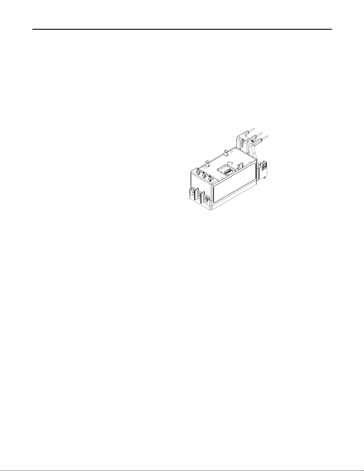
Sensing Module
Figure 1 - Sensing Module
The sensing module electronically samples the current, voltage, power, and
energy data consumed by the electric motor internal to the module. Users can
pick from one of three varieties of the sensing modules depending on the motor
diagnostic information that is needed for the motor protection application:
rrent Sensing
• Cu
• Current and Ground Fault Current Sensing
• Current, Ground Fault Current, Voltage, and Power Sensing
T
current ranges for each of three varieties of sensing module are shown below:
he
• 0.5…30 A
• 6…60 A
• 10…100 A
• 20…200 A
Users can choose how the sensing module mechanically mounts inside the
rical enclosure. The following mounting mechanisms are available for the
elect
sensing module.
• Mount to the load side of an Allen-Bradley Bulletin 100 IEC Contactor
• Mount to the load side of an Allen-Bradley Bulletin 500 NEMA
Cont
actor
• DIN Rail / Panel Mount with power terminals
• Replacement DIN Rail / Panel Mount with power terminals for an
Al
len-Bradley E3 Plus panel mount adapter
• DIN Rail / Panel Mount with pass-thru power conductors
Rockwell Automation Publication 193-UM015B-EN-P - June 2014 15
Page 16
Chapter 1 Product Overview
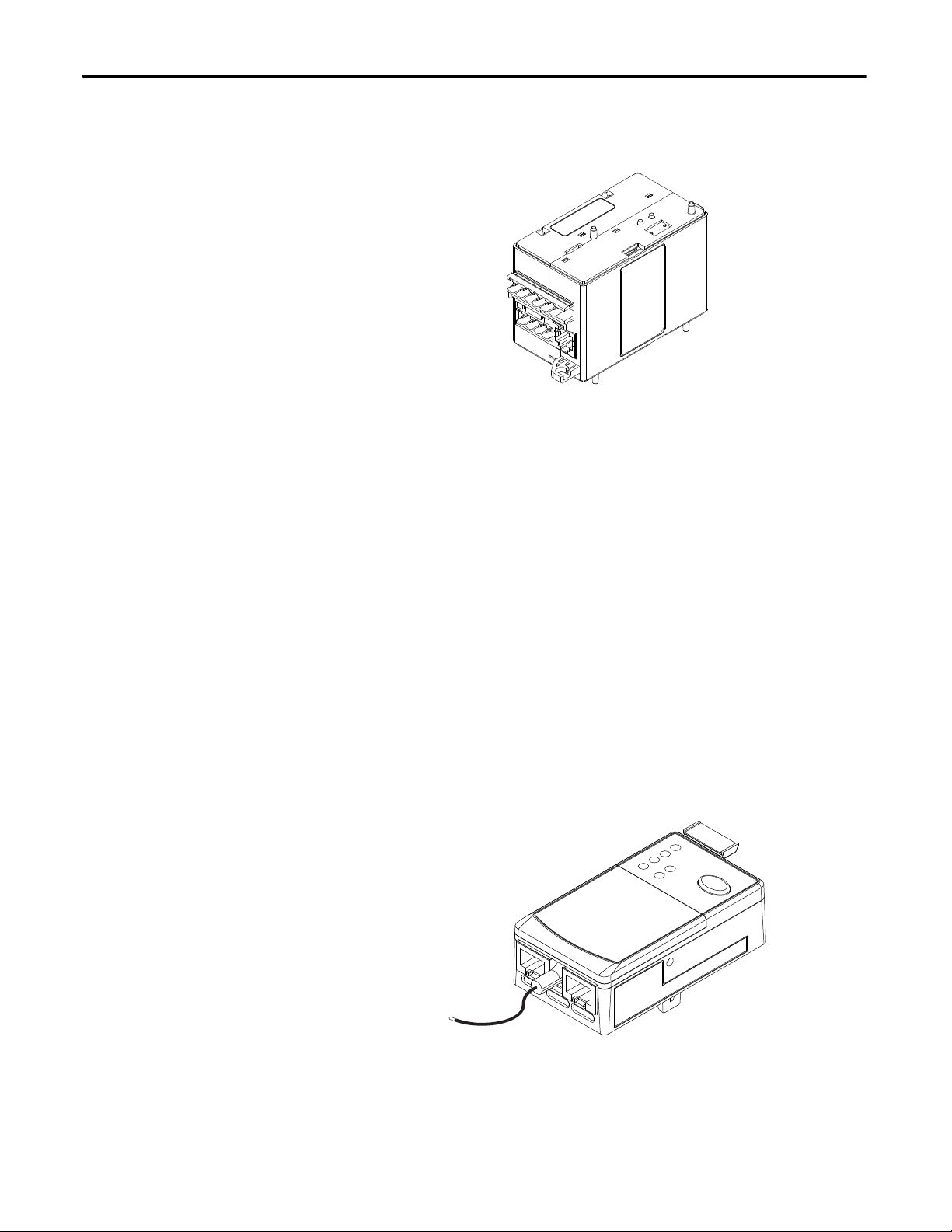
Control Module
Figure 2 - Control Module
The control module is the heart of the E300 Electronic Overload Relay and can
attach to any sensing module. The control module performs all of the protection
and motor control algorithms and contains the native I/O for the system. The
control module has two varieties:
• I/O only
• I/O and prote
ction (PTC & External Ground Fault Current Sensing)
The control module is offered in three control voltages:
• 110…120V AC, 50/60Hz
• 220…240V AC, 50/60Hz
• 24V D
Ext
ernal control voltage is required to power the E300 Electronic Overload Relay
and
activate the digital inputs.
C
Communication Module
Figure 3 - Communication Module
The communication module allows the E300 Electronic Overload Relay to be
integrated into an automation system, and it can attach to any control module.
All communication modules allow the user to set the node address with rotary
16 Rockwell Automation Publication 193-UM015B-EN-P - June 2014
Page 17

Product Overview Chapter 1
turn dials, and it provides diagnostic LEDs to provide system status at the panel.
The E300 Electronic Overload Relay supports two network protocols:
• EtherNet/IP
• DeviceNet
The
E300 EtherNet/IP Communication Module has two RJ-45 connectors that
funct
ion as a switch. Users can daisy chain multiple E300 Electronic Overload
Relays with Ethernet cable, and the module supports a Device Level Ring (DLR).
Optional Add-On Modules
Optional Expansion I/O
The E300 Electronic Overload Relay allows the user to add additional digital and
analog I/O to the system via the E300 Electronic Overload Relay Expansion Bus
if the native I/O count is not sufficient for the application on the base relay. Users
can add up to four additional Digital I/O Expansion Modules that have 4 inputs
(120V AC, 240V AC, or 24V DC) and 2 relay outputs.
Users can also add up to four additional Analog I/O Expansion Modules, which
have three independent universal analog inputs and one isolated analog output.
The independent universal analog inputs can accept the following signals:
• 4…20 m
• 0…20 mA
• 0…10V DC
• 1…5V DC
• 0…5V DC
• RTD Sensors (Pt, Cu, Ni, & NiFe)
• NTC Sensors
o
The is
signa
diagnostic values:
lated analog output can be programmed to reference a traditional analog
l (4…20 mA, 0…20 mA, or 0…10V DC) to represent the following
• Average %FLA
• %TCU
• Ground Fault Current
• Current Imbalance
• Average L-L Voltage
• Voltage Imbalance
• To ta l kW
• To ta l kVA R
• To ta l kVA
• To ta l P ow er Fa cto r
• User Defined Value
A
Rockwell Automation Publication 193-UM015B-EN-P - June 2014 17
Page 18
Chapter 1 Product Overview
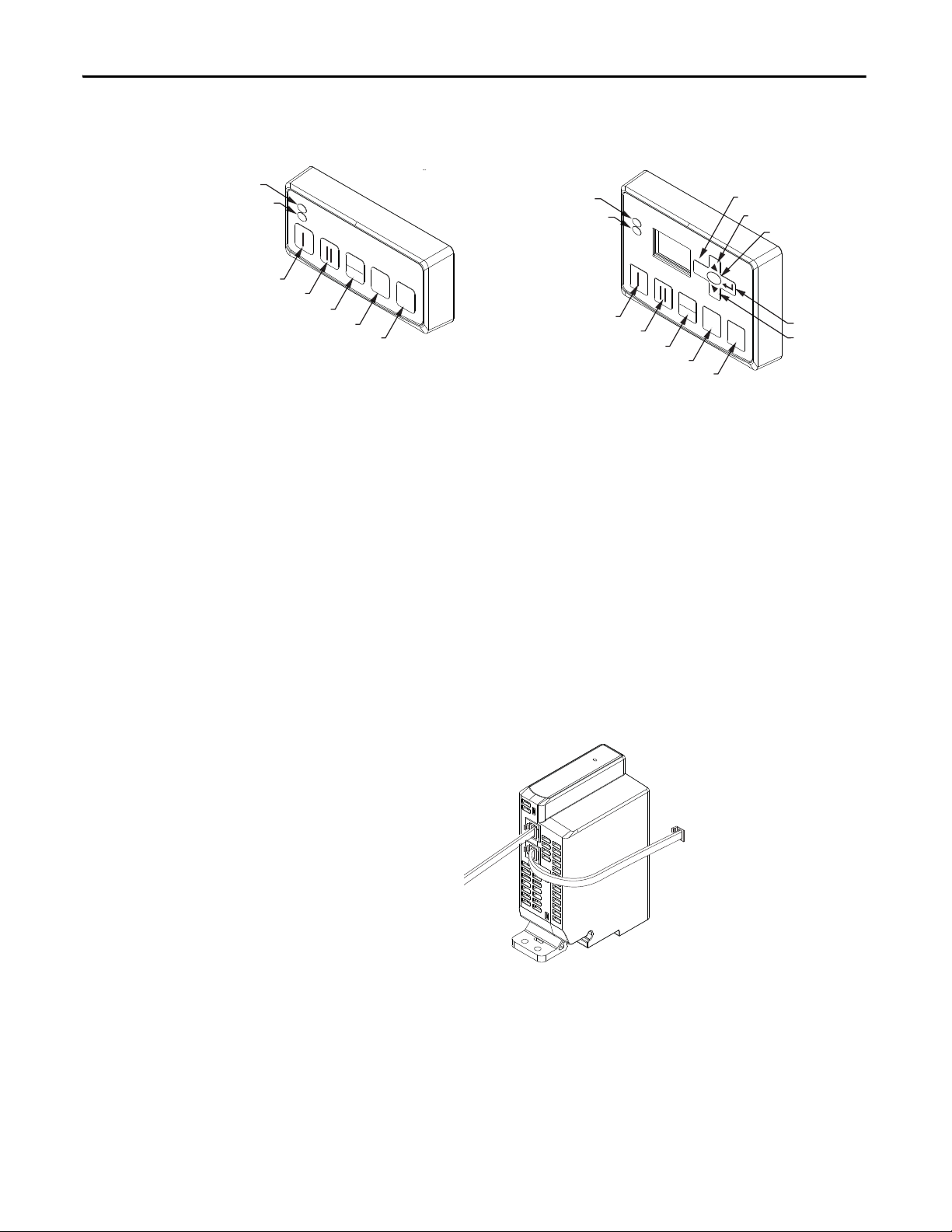
Control Station Diagnostic Station
Optional Operator Station
Figure 4 - Operator Stations
Power LED
Trip / Warn LED
Start Forward / Speed 1
Start Reverse / Speed 2
Local / Remote
Escape
Up
Select
ESC
SELECT
0
RESET
Enter
Down
Stop
LOCAL
REMOTE
Reset
Power LED
Trip / Warn LED
0
RESET
Start Forward / Speed 1
Start Reverse / Speed 2
Local / Remote
Stop
LOCAL
REMOTE
Reset
The E300 Electronic Overload Relay offers the user the capability to add one
operator interface to the Expansion Bus. There are two types of operator stations
that the user can chose from: control station or a diagnostic station. Both types of
operator stations mount into a standard 22 mm push button knockout, and they
provides diagnostic LEDs which allow the user to view the status of the E300
Electronic Overload Relay from the outside of an electrical enclosure. Both
operator stations provide push buttons which can be used for motor control
logic, and they both can be used to upload and download parameter
configuration data from the base relay. The diagnostic station contains a display
and navigation buttons that allows the user to view and edit parameters in the
base relay.
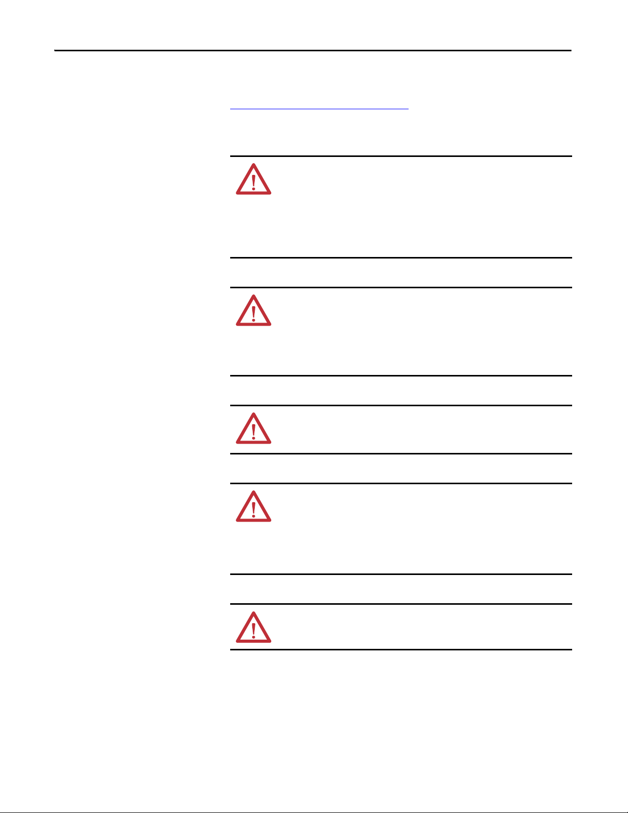
Optional Expansion Bus Power Supply
Figure 5 - Expansion Bus Power Supply
The E300 Electronic Overload Relay expansion bus provides enough current to
operate a system that has (1) Digital Expansion Module and (1) Operator
Station. An E300 Electronic Overload Relay system that contains more
expansion modules will need supplemental current for the Expansion Bus. The
E300 Electronic Overload Relay offers users two types of Expansion Bus Power
Supplies: AC (110…240V AC, 50/60 Hz) and DC (24V DC). One Expansion
Bus Power Supply supplies enough current for a fully loaded E300 Electronic
18 Rockwell Automation Publication 193-UM015B-EN-P - June 2014
Page 19

Product Overview Chapter 1
Overload Relay Expansion Bus (four Digital Expansion Modules, four Analog
Expansion Modules, and one Operator Station).
Protection Features
Standard Current-Based Protection
All versions of the E300 Electronic Overload Relay provide the following motor
protection functions:
• Thermal Overload (51)
• Phase Loss
• Current Imbalance (46)
• Undercurrent – load loss (37)
• Overcurrent – load jam (48)
• Overcurrent – load stall
• Start Inhibit (66)
Ground Fault Current Based Protection
The E300 Electronic Overload Relay sensing modules and control modules with
a ground fault current option provides the following motor protection function:
• Ground Fault – zero sequence method (50N)
Voltage and Power Based Protection
The E300 Electronic Overload Relay sensing modules with voltage sensing
provides the following motor protection functions:
• Undervoltage (27)
• Overvoltage (59)
• Phase Reversal (47) – voltage based
• Over and Under Frequency (81) – voltage based
• Voltage Imbalance (46)
• Over and Under Power (37)
• Over and Under Leading/Lagging Power Factor (55)
• Over and Under Reactive Power Generated
• Over and Under Reactive Power Consumed
• Over and Under Apparent Power
Rockwell Automation Publication 193-UM015B-EN-P - June 2014 19
Page 20

Chapter 1 Product Overview
Applications:
The E300 Electronic Overload Relay can be used with the following across the
line starter applications:
• Non-Reversing Starter
• Reversing Starter
• Wye (Star) / Delta Starter
• Two -s pe ed Motors
• Low and Medium Voltage with 2 or 3 Potential Transformers
• With or Without Phase Current Transformers
• With or Without Zero-sequence Core Balanced Current Transformer
20 Rockwell Automation Publication 193-UM015B-EN-P - June 2014
Page 21

Installation and Wiring
Chapter 2
Introduction
Receiving
Unpacking/Inspecting
Storing
This chapter provides instructions for receiving, unpacking, inspecting, and
storing the E300™ Electronic Overload Relay. Assembly, installation, and wiring
instructions for common applications are also included in this chapter.
It is the responsibility of the user to thoroughly inspect the equipment before
accepting the shipment from the freight company. Check the item(s) received
against the purchase order. If any items are damaged, it is the responsibility of the
user not to accept delivery until the freight agent has noted the damage on the
freight bill. Should any concealed damage be found during unpacking, it is again
the responsibility of the user to notify the freight agent. The shipping container
must be left intact and the freight agent should be requested to make a visual
inspection of the equipment.
Remove all packing material from around the E300 Electronic Overload Relay.
After unpacking, check the item’s nameplate catalog number against the purchase
order.
The E300 Electronic Overload Relay should remain in its shipping container
prior to installation. If the equipment is not to be used for a period of time, it
must be stored according to the following instructions in order to maintain
warranty coverage:
• Store in a clean, dry location.
• Store within an ambient temperature range
-40…+85 °C (-40…+185
of
• Store within a relative humidity range of 0…95%, non-condensing.
• Do not store where the device could be exposed to a corrosive atmosphere.
• Do not store in a construction area.
°F).
Rockwell Automation Publication 193-UM015B-EN-P - June 2014 21
Page 22
Chapter 2 Installation and Wiring
General Precautions
If the E300 Electronic Overload Relay is being deployed in an environment with
an ambient temperature greater than 30 °C (86 °F), please refer to the
Environmental Specifications on page 325
derating. In addition to the specific precautions listed throughout this manual,
the following general statements must be observed.
ATT EN TI ON : The E300 Electronic Overload Relay contains electrostatic
discharge (ESD) sensitive parts and assemblies. Status control precautions are
required when installing, testing, servicing, or repairing this assembly.
Component damage may result if ESD control procedures are not followed. If
you are not familiar with static control procedures, refer to Allen-Bradley
publication 8000-SB001_-en-p, “Guarding Against Electrostatic Damage”, or
any other applicable ESD protection handbook.
ATT EN TI ON : An incorrectly applied or installed E300 Electronic Overload Relay
can result in damage to the components or reduction in product life. Wiring or
application errors (e.g., incorrectly figuring the FLA setting, supplying incorrect
or inadequate supply voltage, connecting an external supply voltage to the
thermistor terminals, or operating or storing in excessive ambient
temperatures) may result in malfunction of the E300 Electronic Overload Relay.
for the appropriate temperature
Base Relay Assembly
ATT EN TI ON : Only personnel familiar with the E300 Electronic Overload Relay
and associated machinery should plan to install, start up, and maintain the
system. Failure to comply may result in personal injury or equipment damage.
ATT EN TI ON : The purpose of this user manual is to serve as a guide for proper
installation. The National Electrical Code (NEC) and any other governing
regional or local code will overrule this information. Rockwell Automation
cannot assume responsibility for the compliance or proper installation of the
Electronic Overload Relay or associated equipment. A hazard of personal
E300
injury and/or equipment damage exists if codes are ignored during installation.
ATT EN TI ON : The earth ground terminal of the E300 Electronic Overload Relay
shall be connected to a solid earth ground via a low-impedance connection.
The following section illustrates the E300 Electronic Overload Relay base relay
assembly instructions.
22 Rockwell Automation Publication 193-UM015B-EN-P - June 2014
Page 23
Installation and Wiring Chapter 2
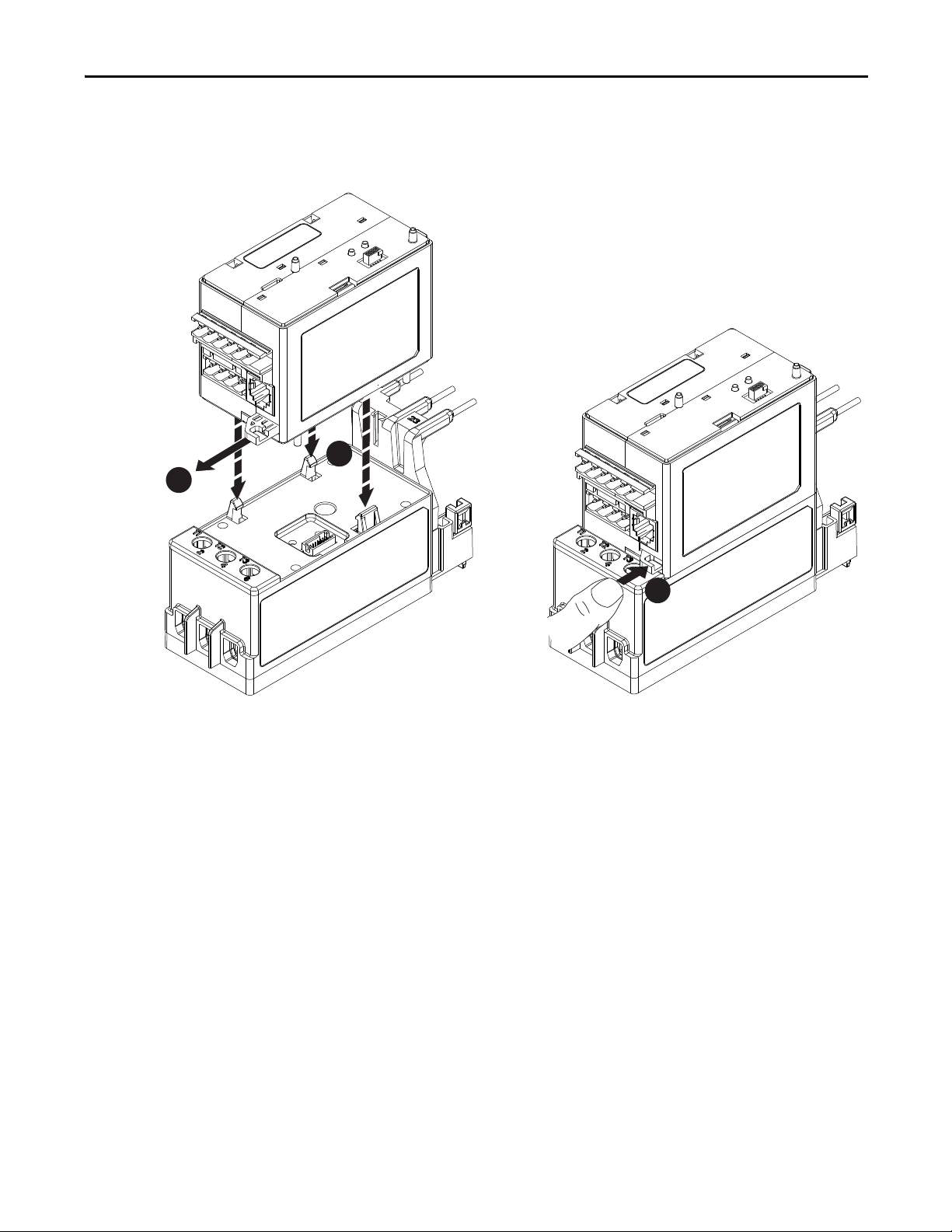
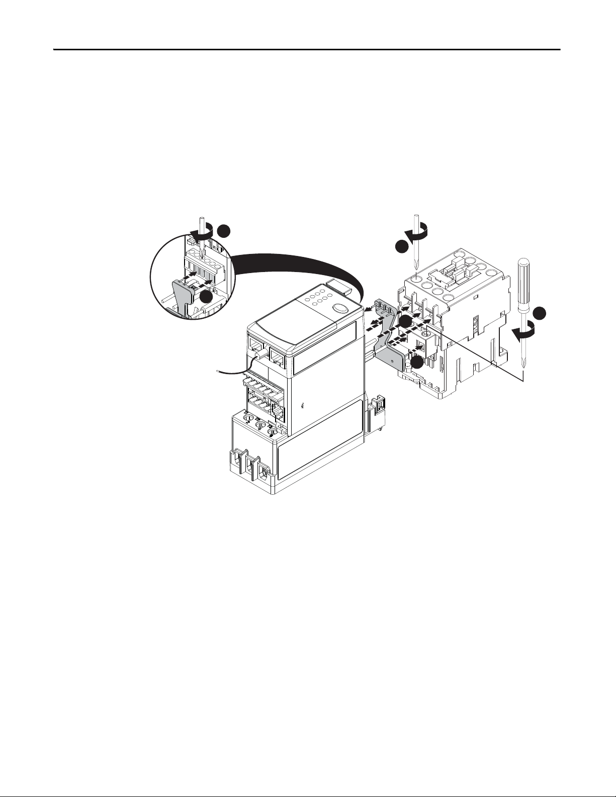
Control Module to Sensing Module Assembly
1
Any E300 Control Module can connect to any E300 Sensing Module. The
illustrations below show the steps required to make this connection.
Figure 6 - Control Module to Sensing Module Assembly\
2
3
Rockwell Automation Publication 193-UM015B-EN-P - June 2014 23
Page 24
Chapter 2 Installation and Wiring
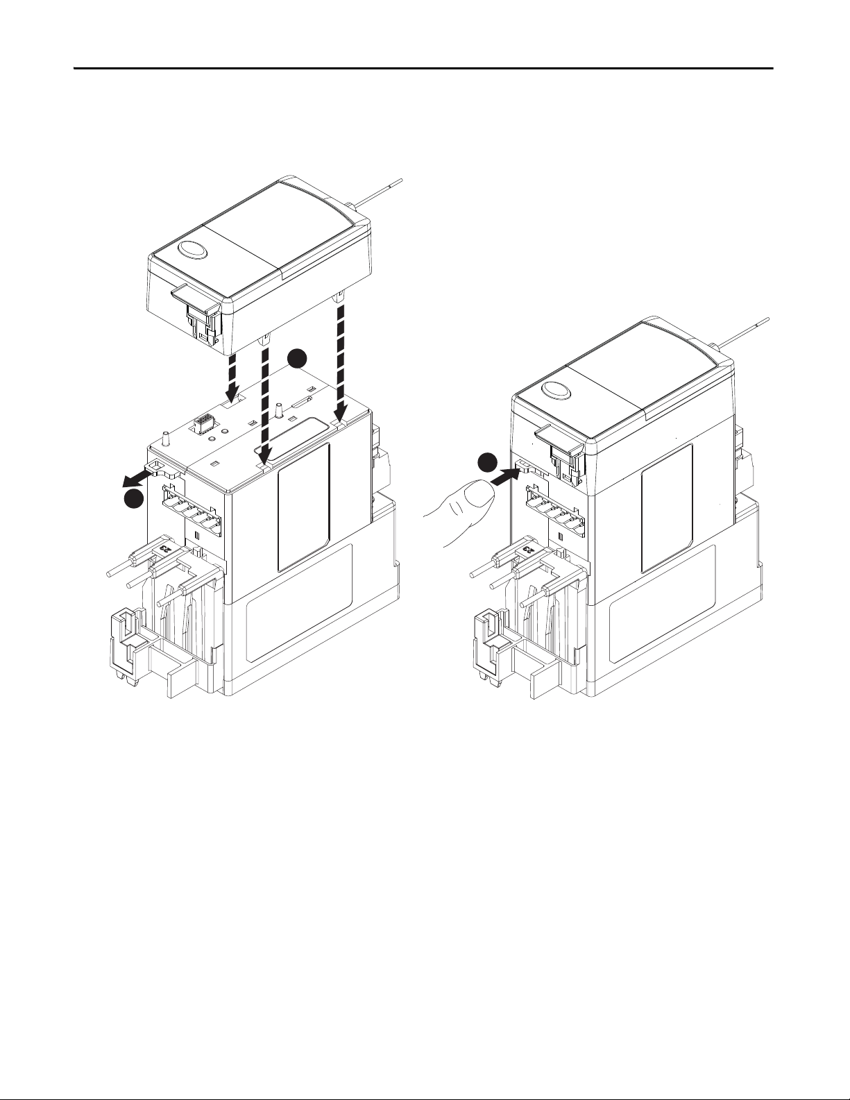
1
3
2
Communication Module to Control Module Assembly
Any E300 Communication Module can connect to any E300 Control Module.
The illustrations below show the steps required to make this connection.
Figure 7 - Communication Module to Control Module Assembly
24 Rockwell Automation Publication 193-UM015B-EN-P - June 2014
Page 25
Installation and Wiring Chapter 2
Start Forward / Speed 1
Start Reverse / Speed 2
Local / Remote
Stop
Reset
Start Forward / Speed 1
Start Reverse / Speed 2
Local / Remote
Stop
Up
Down
Reset
Escape
Power LED
Trip / Warn LED
Power LED
Trip / Warn LED
Enter
Select
0
RESET
LOCAL
REMOTE
0
RESET
SELECT
ESC
REMOTE
LOCAL
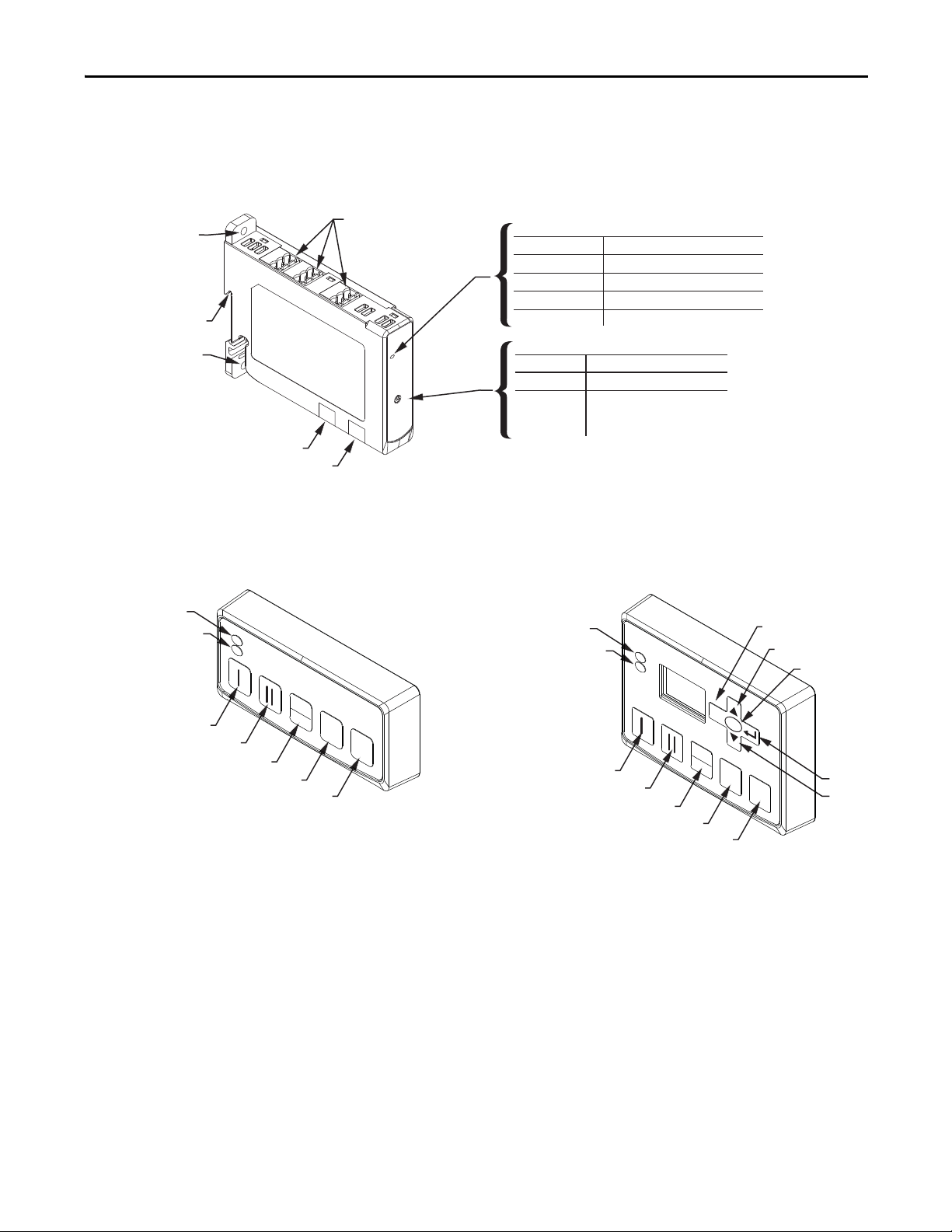
Control Station Diagnostic Station
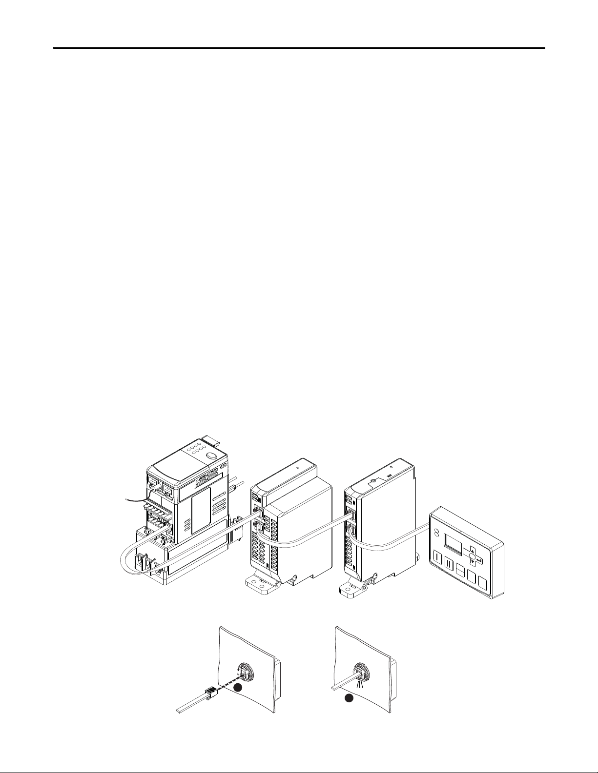
Expansion Bus Peripherals
Panel Mount
Hole
DIN Rail Mount
Panel Mount Hole
Expansion Bus Out
Expansion Bus In
The E300 Electronic Overload Relay offers a range of Expansion Digital and
Analog I/O modules that simply connect to the E300 Electronic Overload
Relay’s Expansion Bus.
Figure 8 - Expansion Bus Peripherals
Removable I/O Terminals
3
2
4
4T
1
3T
1T
2T
Color
Blinking Green
Green Module OK and active
Module Number Selector
Number
1 - 4
1T - 4T
Note: If the expansion bus does not have an operator station, then the
last expansion module number must be set to terminated.
Status LED
Description
O
No power applied
Module OK with no connection
Red Error Detected
Description
Module number
Module number with
expansion bus terminating
resistor applied
Users can also add one of the two available operator stations to the end of the
Expansion Bus.
Figure 9 - Expansion Operator Stations
The following illustrations show how to mount and connect the E300 Electronic
Overload Relay expansion bus I/O modules, expansion power supplies, and
operator stations.
Rockwell Automation Publication 193-UM015B-EN-P - June 2014 25
Page 26
Chapter 2 Installation and Wiring
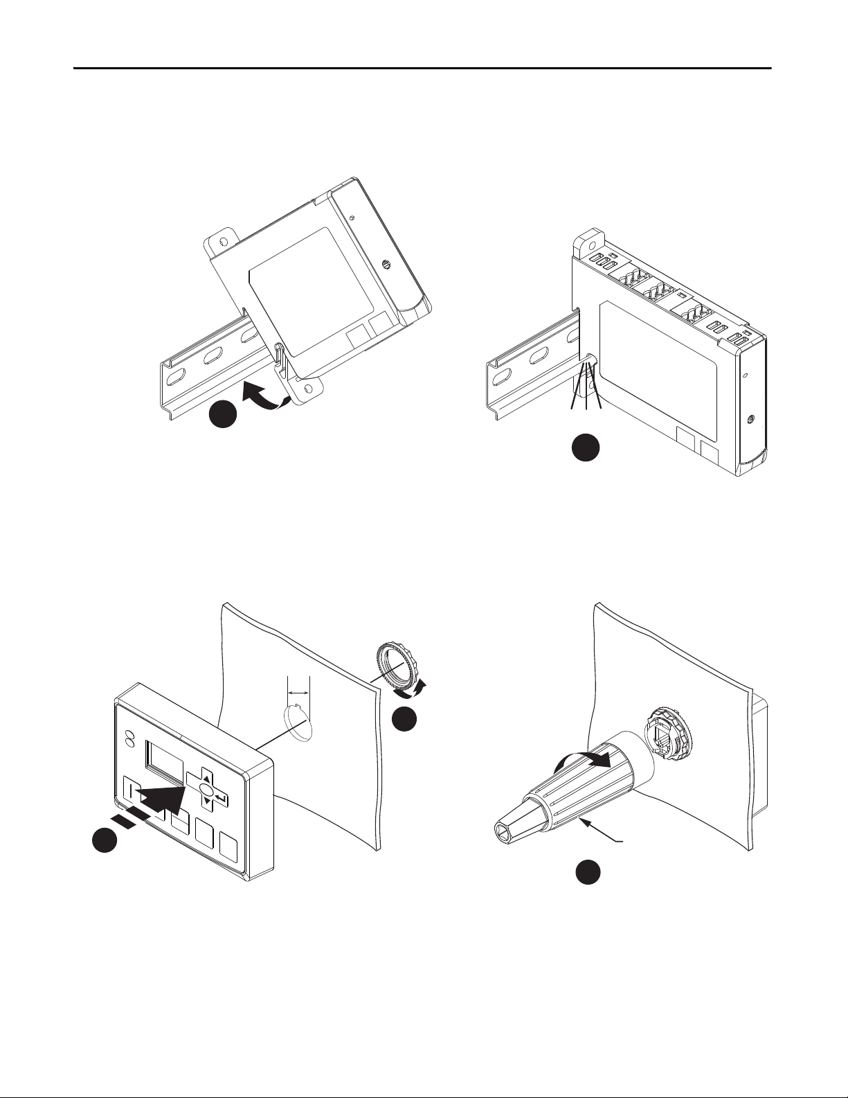
1
2
Click
2
1
1.7 N.m
(15 lb-in)
0
RESET
SELECT
ESC
REMOTE
LOCAL
800F-AW2
3
22 mm
Expansion Bus Digital & Analog I/O Modules and Power Supply Installation
Figure 10 - Expansion Bus Digital& Analog I/O Modules and Power Supply
Expansion Bus Operator
Figure 11 - Expansion Bus Operator Station
Station Installation
Expansion Bus Network Installation
26 Rockwell Automation Publication 193-UM015B-EN-P - June 2014
The E300 Electronic Overload Relay will support up (4) Expansion Digital I/O
modules, (4) Expansion Analog I/O modules, and (1) Operation Station. The
E300 Base Relay can supply enough power for (1) Expansion Digital I/O module
and (1) Operator Station. Any other combination of E300
Expansion Bus
Page 27
Installation and Wiring Chapter 2
0
RESET
SELECT
ESC
REMOTE
LOCAL
Click
1
2
peripherals will require an Expansion Bus Power Supply which connects as the
first module on the Expansion Bus.
Users will set the address dial of the Expansion Digital Module to a unique digital
module address number (1-4). If the Expansion Digital Module is the last device
on the Expansion Bus, set the address to the address value that enables in the
internal terminating resistor (1T-4T). A power cycle is required when changes
are made to the address dial.
Users will set the address dial of the Expansion Analog Module to a unique
analog module address number (1-4). If the Expansion Analog Module is the last
device on the Expansion Bus, set the address to the address value that enables in
the internal terminating resistor (1T-4T). A power cycle is required when
changes are made to the address dial.
Users will connect the E300 Base Relay to the Expansion Module’s Input Port
using the supplied Expansion Bus cable. Users will add the next Expansion
Module by connecting the supplied Expansion Bus cable to the Output Port of
the previous Expansion Module and into the Input Port of the additional
Expansion Module. The Operator Stations is the last device on the E300
Expansion Bus; it only has an Input Port with an internal Expansion Bus
terminating resistor.
If the user supplied Expansion Bus cable is not long enough for the installation,
1-meter (Cat. No. 193-EXP-CBL-1M) and 3-meter (Cat. No.
193-EXP-CBL-3M) Expansion Bus cables are available as accessories. The E300
expansion bus can support a maximum distance of 5 meters (16 ft.).
Figure 12 - Expansion Bus Network Installation
Rockwell Automation Publication 193-UM015B-EN-P - June 2014 27
Page 28
Chapter 2 Installation and Wiring
Starter Assembly
5 - 7 lb-in
IN1
The following illustrations show how to assemble an E300 Electronic Overload
Relay as a motor starter with an Allen-Bradley Bulletin 100-C contactor.
100-C09…-C55 Starter Assembly Installation
The starter assembly installation instructions are for use with E300 Sensing
Module catalog numbers 193-ESM-___-___-C23 and 193-ESM-___-___-C55
Figure 13 - 100-C09…-C55 Starter Assembly Installation
6
9 - 22 lb-in
IN0
A2
R04
R03
A1
4
5
3
2
7 -11 lb-in
1
28 Rockwell Automation Publication 193-UM015B-EN-P - June 2014
Page 29
Installation and Wiring Chapter 2
45
(1.76)
87
(3.40)
60 (2.3
35
(1.37)
n 5 (0.18)
190 (7.49)
37 (1.47)
122 (4.81)
29 (1.14)
122
(4.78)
152 (5.98)
67 (2.65)
FROM
CONTACTOR
MTG. HOLE
FROM
CONTACTOR
MTG. HOLE
(ADD 5 mm (0.19 in.)
FOR CONTACTOR COIL
ON LINE SIDE)
37 (1.48)
122 (4.81)
29 (1.13)
190 (7.49)
67 (2.65)
152 (5.98)
45
(1.76)
122
(4.78)
104
(4.10)
35
(1.374)
60 (2.36)
n 5 (0.18)
(ADD 5 mm (0.19 in.)
FOR CONTACTOR COIL
ON LINE SIDE)
FROM
CONTACTOR
MTG. HOLE
FROM
CONTACTOR
MTG. HOLE
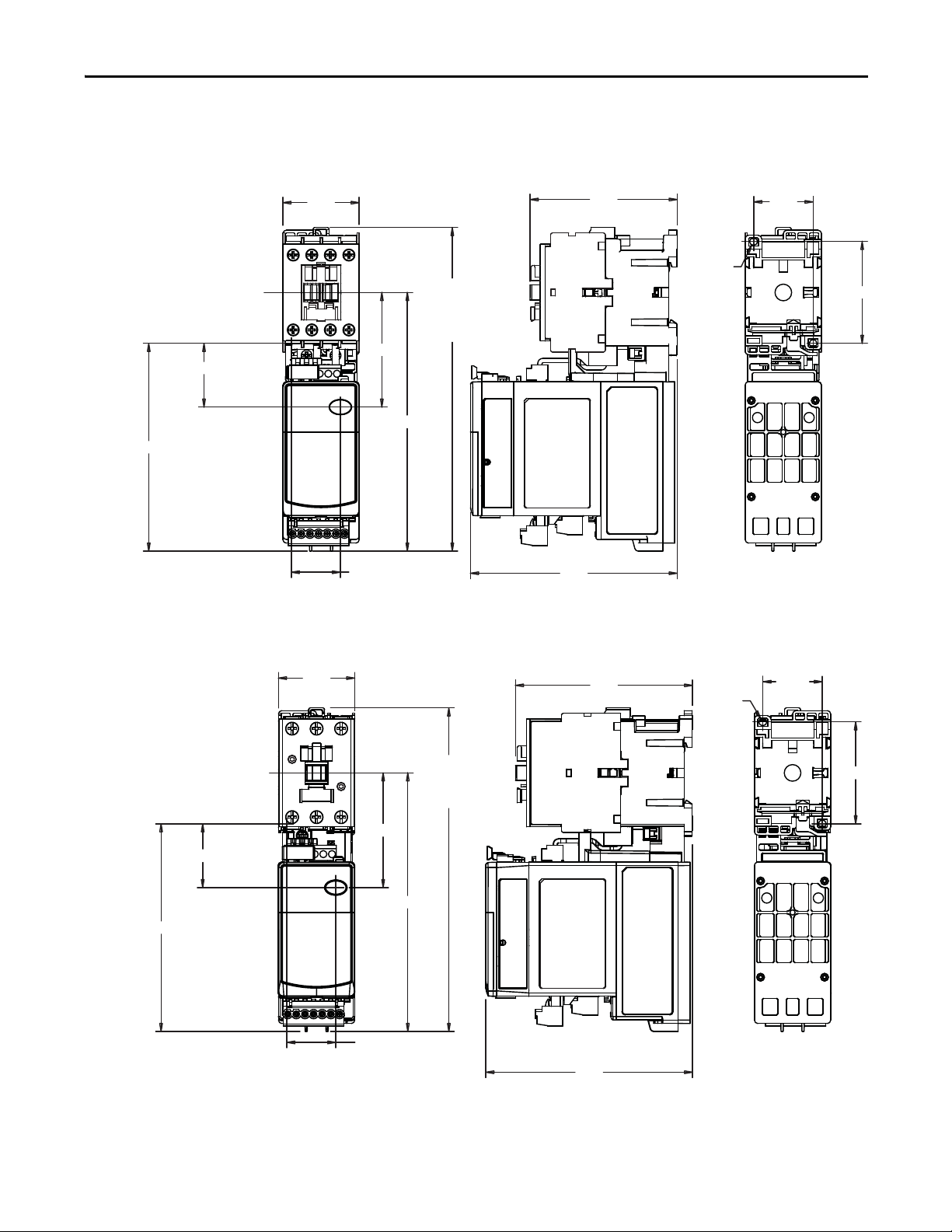
Starter Dimensions
Approximate dimensions are shown in millimeters (inches). Dimensions are not
intended to be used for manufacturing purposes.
Figure 14 - E300 Sensing Module 193-ESM-___-__-C23 with 100-C09…-C23 Contactor
Figure 15 - E300 Sensing Module 193-ESM-___-__-C55 with 100-C30…-C37 Contactor
Rockwell Automation Publication 193-UM015B-EN-P - June 2014 29
Page 30
Chapter 2 Installation and Wiring
54
(2.12)
45 (1.76)
190 (7.49)
107
(4.21)
60 (2.
45 (1.75)
n 5 (0.18)
37 (1.48)
34 (1.34)
122
(4.82)
152 (5.98)
67 (2.65)
FROM
CONTACTOR
MTG. HOLE
FROM
CONTACTOR
MTG. HOLE
(ADD 5 mm (0.19 in.)
FOR CONTACTOR COIL
ON LINE SIDE)
180 (7.06)
157 (6.17)
249 (9.78)
35 (1.38)
70
(2.75)
12 (0.46)
n 6 (0.22)
90
(3.56)
125
(4.91)
Figure 16 - E300 Sensing Module 193-ESM-___-__-C55 with 100-C43…-C55 Contactor
Figure 17 - E300 Sensing Module 592-ESM-___-__-S2 with NEMA Contactor Size 0 and Size 1
30 Rockwell Automation Publication 193-UM015B-EN-P - June 2014
Page 31

Installation and Wiring Chapter 2
219 (8.63)
184 (7.24)
276 (10.85)
n 6 (0.22)
100
(3.94)
40 (1.58)
80
(3.15)
125
(4.91)
12 (0.46)
45
(1.764)
135 (5.32)
30
(1.18)
n 5 (0.17)
6 (0.24)
6 (0.217)
9 (0.33)
148 (5.83)
4 (0.154)
46 (1.81)
4 (0.14)
126
(4.94)
101 (3.96)
4 (0.16)
8 (0.30)
q
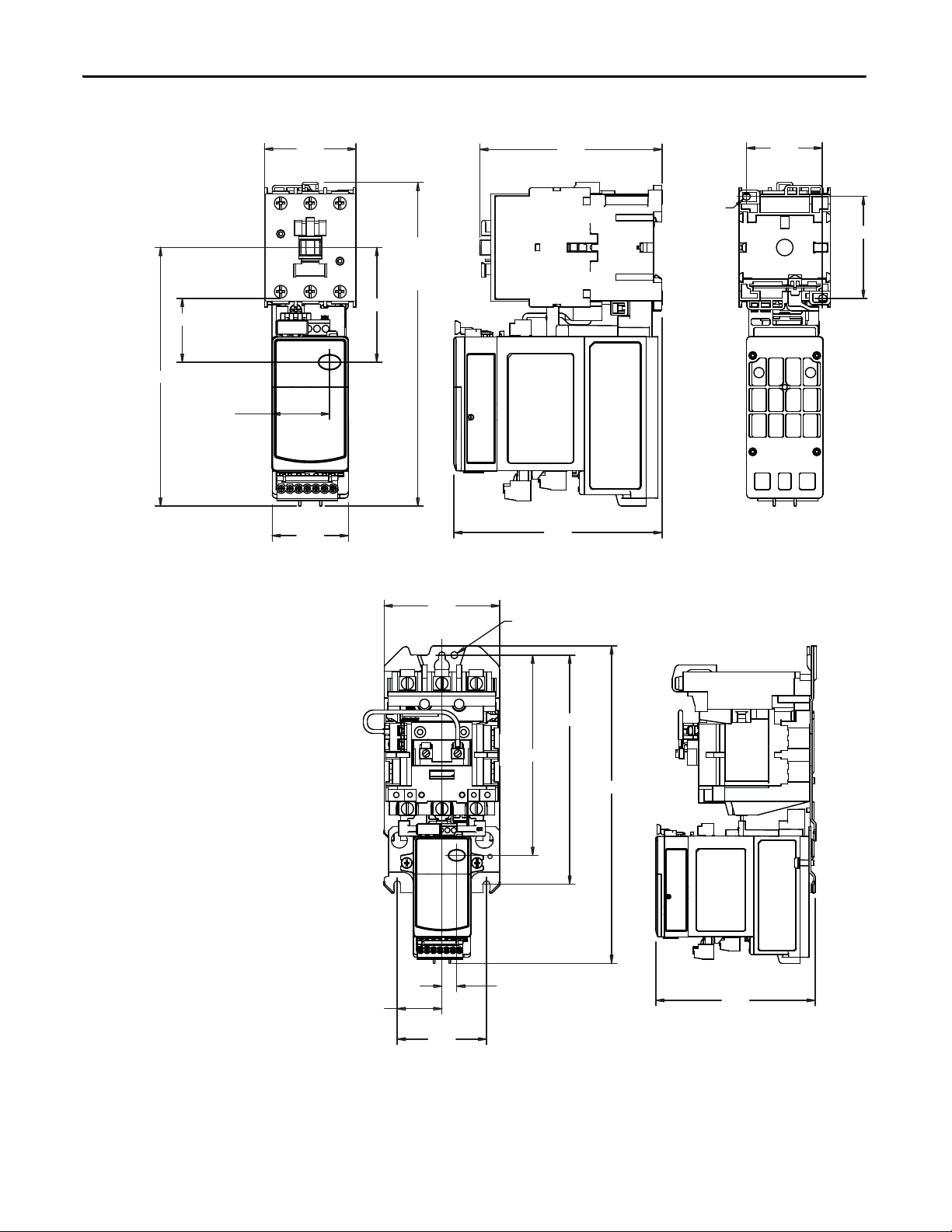
Figure 18 - E300 Sensing Module 592-ESM-___-__-S2 with NEMA Contactor Size 2
DIN Rail / Panel Mount Dimensions
Approximate dimensions are shown in millimeters (inches). Dimensions are not
intended to be used for manufacturing purposes.
Figure 19 - E300 Sensing Module 193-ESM-___-30A-E3T and 193-ESM-___-60A-E3T
Rockwell Automation Publication 193-UM015B-EN-P - June 2014 31
Page 32

Chapter 2 Installation and Wiring
2 x 4.5 (0.18) dia.
22.5
(0.89)
80.75 (3.18)
120
(4.73)
98 (3.86)
87 (3.43)
2 x 4.5 (0.18) dia.
22.5
(0.89)
80.75 (3.18)
120
(4.73)
98 (3.86)
87 (3.43)
Expansion Bus Peripherals Dimensions
Approximate dimensions are shown in millimeters. Dimensions are not intended
to be used for manufacturing purposes.
Figure 20 - E300 Digital Expansion Module 193-EXP-DIO-___
Figure 21 - E300 Expansion Analog Module 193-EXP-AIO
32 Rockwell Automation Publication 193-UM015B-EN-P - June 2014
Page 33

Figure 22 - E300 Expansion Power Supply 193-EXP-PS-___
120
(4.73)
80.75 (3.18)
45
(1.77)
4x 4.5 (0.18) dia
98
(3.86)87(3.43)
12
(0.47)
22.5 (0.89) dia.
18.5
(0.73)
13.5 (0.53)
100
(3.94)
70
(2.76)
Installation and Wiring Chapter 2
100
(3.94)
45 (1.77)
Figure 23 - E300 Starter Control Station 193-EOS-SCS
18.5
(0.73)
13.5
(0.53)
Figure 24 - E300 Starter Diagnostic Station 193-EOS-SDS
22.5 (0.89) dia.
Rockwell Automation Publication 193-UM015B-EN-P - June 2014 33
Page 34

Chapter 2 Installation and Wiring
Terminals
Sensing Module
Table 1 - E300 Sensing Module Wire Size and Torque Specifications
Wire Type Conductor Torque
Single
Stranded/Solid [AWG]
Multiple
Single
Flexible-Stranded with Ferrule Metric
Multiple
Single
Coarse-Stranded/Solid Metric
Multiple
Cat. No.
193-ESM-_ _ _-30A-_ _ _
193-ESM-_ _ _-60A-_ _ _
592-ESM-_ _ _-30A-_ _ _
592-ESM-_ _ _-60A-_ _ _
#14…6 AWG
22 lb-in.
#10…6 AWG
30 lb-in.
2.5…16 mm2
2.5 N•m
6…10 mm2
3.4 N•m
2.5…25 mm2
2.5 N•m
6…16 mm2
3.4 N•m
193-ESM-_ _ _-100A-_ _ _
592-ESM-_ _ _-100A-_ _ _
#12…1 AWG
35 lb-in.
#6…2 AWG
35 lb-in.
4…35 mm2
4 N•m
4…25 mm2
4 N•m
4…50 mm2
4 N•m
4…35 mm2
4 N•m
34 Rockwell Automation Publication 193-UM015B-EN-P - June 2014
Page 35

Control Module
193-EIOGP-42- _ _ _
193-EIOGP-22- _ _ _
Sensing Module Latch
Power / PTC
Terminals
Expansion Bus Connector
Relay / Ground Fault
Terminals
R13
R14
S1
S2
A1
A1
A2
IN2
IN3
IT1
IT2
R13
R14
S1
S2
193-EIO-63- _ _ _
193-EIO-43- _ _ _
R13
R14
R23
R24
A1
A1
A2
IN2
IN3
IN4
IN5
R13
R14
R23
R24
A1
A1
A2
IN2
IN3
A1
A1
A2
IT1
IT2
Input / Output
Terminals
Communication
Module Latch
IN1
IN0
A2
A1
R04
R03
Figure 25 - E300 Control Module Terminal Designations
Installation and Wiring Chapter 2
Rockwell Automation Publication 193-UM015B-EN-P - June 2014 35
Page 36

Chapter 2 Installation and Wiring
R24R23
RELAY 2RELAY 1
R14R13
IN3
IN2
Additional Inputs for 193-EIO-63-_ _ _
IN0
IN1
A2
PE
A1A1
A1
R03
R04
A2
IN5
IN4
(+)
(-)
RELAY 0
S2S1
RELAY 1
R14R13
IN3
IN2
IN0
IN1
A2
A1A1
A1
R03
R04
A2
IT2
IT1
(+)
(-)
RELAY 0
193-EIOGP-_ _-_ _ _193-EIO-_ _-_ _ _
PE
Ground
Fault
PTC
Additional Inputs for 193-EIOGP-42-_ _ _
+
t
Table 2 - E300 Control Module Wire Size and Torque Specifications
Cat. No.
Wire Type Conductor Torque
193-EIO-_ _-_ _ _
193-EIOGP-_ _-_ _ _
Single 24...12 AWG
Stranded/Solid [AWG]
Flexible-Stranded with Ferrule
Metric
Coarse-Stranded/Solid Metric
Multiple
(stranded only)
24...16 AWG
5 lb-in
Single 0.25…2.5 mm
Multiple
0.5...0.75 mm
0.55 N•m
Single 0.2...2.5 mm
Multiple
0.2...1.5 mm
0.55 N•m
2
2
2
2
Figure 26 - Control Module Wiring
36 Rockwell Automation Publication 193-UM015B-EN-P - June 2014
Page 37

Expansion Digital Module
IN0 IN1 INC
IN2 IN3
RS2
R04 R14 RC3
Figure 27 - E300 Expansion Digital Module Terminal Designations
Installation and Wiring Chapter 2
Table 3 - E300 Expansion Digital Module Wire Size and Torque Specifications
Wire Type Conductor Torque
Single 24...12 AWG
Stranded/Solid [AWG]
Multiple
(stranded only)
Single 0.25…2.5 mm
Flexible-Stranded with Ferrule Metric
Multiple
Single 0.2...2.5 mm
Coarse-Stranded/Solid Metric
Multiple
Cat. No.
193-EXP-DIO-42-_ _ _
24...16 AWG
5 lb-in
0.5...0.75 mm
0.55 N•m
0.2...1.5 mm
0.55 N•m
2
2
2
2
Rockwell Automation Publication 193-UM015B-EN-P - June 2014 37
Page 38

Chapter 2 Installation and Wiring
R04 R14 RC3
IN0 INCIN1 IN2 IN3
Source
+
-
IN1+ IN1- RS1
IN2+ IN2- RS2
OUT+OUT-
IN0+ IN0- RS0
Figure 28 - E300 Expansion Digital Module Wiring Diagram
Expansion Analog Module
Figure 29 - E300 Expansion Analog Module Terminal Designations
38 Rockwell Automation Publication 193-UM015B-EN-P - June 2014
Page 39

Installation and Wiring Chapter 2
Analog Current Input Analog Voltage Input
24V DC
Power
Supply
INx+
IN
x
-
+
-
Current
Input
Device
INx+
-
V
+V
INx-
Analog Voltage or Current Output
+
Out
-
Out+
Device
-
2 Wire RTD
INx+
INx-
INx-
3 Wire RTD
INx+
RS
x
Table 4 - E300 Expansion Analog Module Wire Size and Torque Specifications
Wire Type Conductor Torque
Single 24...12 AWG
Stranded/Solid [AWG]
Flexible-Stranded with Ferrule Metric
Coarse-Stranded/Solid Metric
Multiple
(stranded only)
Single 0.25…2.5 mm
Multiple
Single 0.2...2.5 mm
Multiple
Figure 30 - E300 Expansion Analog I/O Modules 193-EXP-AIO-__
Cat. No.
193-EXP-AIO-31
24...16 AWG
5 lb-in
0.5...0.75 mm
0.55 N•m
0.2...1.5 mm
0.55 N•m
2
2
2
2
Rockwell Automation Publication 193-UM015B-EN-P - June 2014 39
Page 40

Chapter 2 Installation and Wiring
A1 A2
A1 A2
Source
+
-
Expansion Power Supply
Figure 31 - E300 Expansion Power Supply Terminal Designations
Table 5 - E300 Expansion Power Supply Wire
Wire Type Conductor Torque
Stranded/Solid [AWG]
Flexible-Stranded with Ferrule Metric
Coarse-Stranded/Solid Metric
Size and Torque Specifications
Single 24...12 AWG
Multiple
(stranded only)
Single 0.25…2.5 mm
Multiple
(stranded only)
Single 0.2...2.5 mm
Multiple
(stranded only)
Figure 32 - E300 Expansion Power Supply Wiring Diagram
Cat. No.
193-EXP-PS-_ _
24...16 AWG
5 lb-in
0.5...0.75 mm
0.55 N•m
0.2...1.5 mm
0.55 N•m
2
2
2
2
40 Rockwell Automation Publication 193-UM015B-EN-P - June 2014
Page 41

Installation and Wiring Chapter 2
Grounding
Short-Circuit Ratings
The following grounding recommendations are provided to ensure EMC
requirements during installation
.
• The earth ground terminal of the E300 Electronic Overload Relay shall be
connected to a solid earth ground via a low-impedance connection.
• Wire the green shield wire of the Cat. No. 193-ECM-ETR into the earth
ound terminal of the E300 control module.
gr
• Installations employing an external ground fault sensor shall ground the
cable shield
at the sensor with no connection made at the E300 Electronic
Overload Relay.
• The PTC thermistor cable shield shall be grounded at the E300 Electronic
Ov
erload Relay with no connection made at the opposite end.
The E300 Electronic Overload Relay is suitable for use on circuits capable of
delivering not more than the RMS symmetrical amperes listed in the following
tables.
Table 6 - Standard Fault Short Circuit Ratings per UL60947-4-1 and CSA 22.2 No. EN60947-4-1
Overload Relay using Sensing Module Cat. No. Max. Available Fault Current [A] Maximum Voltage [V]
193-ESM-___-30A-C23
193-ESM-___-30A-C55
193-ESM-___-30A-E3T
193-ESM-___-30A-P
193-ESM-___-30A-T
193-ESM-VIG-30A-CT
592-ESM-___-30A-S2
193-ESM-___-60A-C55
193-ESM-___-60A-E3T
193-ESM-___-60A-P
193-ESM-___-60A-T
592-ESM-___-60A-S2
5,000 600
Table 7 - Short Circuit Ratings per EN60947-4-1
Overload Relay using Sensing Module Cat. No.
193-ESM-___-30A-C23
193-ESM-___-30A-C55
193-ESM-___-30A-E3T
193-ESM-___-30A-P
193-ESM-___-30A-T
193-ESM-VIG-30A-CT
592-ESM-___-30A-S2
193-ESM-___-60A-C55
193-ESM-___-60A-E3T
193-ESM-___-60A-P
193-ESM-___-60A-T
592-ESM-___-60A-S2
Rockwell Automation Publication 193-UM015B-EN-P - June 2014 41
Prospective Short-
Circuit Current, Ir [A]
3,000 100,000 690
Conditional Short-Circuit
Current, Iq [A]
Maximum Voltage [V]
Page 42

Chapter 2 Installation and Wiring
Table 8 - High Fault Short Circuit Ratings per UL60947-4-1 and CSA 22.2 No. EN60947-4-1 with Bul.
100-C and 100-D IEC contactors protected by fuses
Overload Relay using
Sensing Module Cat. No.
193-ESM-___-30A-C23
193-ESM-___-30A-C55,
193-ESM-___-60A-C55
Overload Relay using
Sensing Module Cat. No.
193-ESM-___-30A-C23
193-ESM-___-30A-C23
193-ESM-___-30A-C23
Contactor Cat. No. Max. Starter FLC[A]
100-C09 9
100-C12 12 20
100-C16 16 30
100-C23 23 30
100-C30 30 50
100-C37 37 50
100-C43 43 70
100-C55 55 80
Max. Available Fault
Current [A]
100,000 600
Max. Voltage [V] Class C or JJ fuse [A]
Table 9 - Short Circuit Ratings per UL60947-4-1 and CSA 22.2 No. EN60947-4-1 with Bul. 100-C IEC
contactors protected by Bul. 140U-D circuit breakers
Contactor Cat. No. Max. Starter FLC[A]
100-C09 9
100-C12 12
100-C16 16
100-C23 23
100-C09 9
100-C12 12
100-C16 16
100-C23 23
100-C09 9
100-C12 12
100-C16 16
100-C23 23
Max. Available Fault
Current [A]
65,000 480Y/277V C30 (30 A)
35,000 600Y/347V C30 (30 A)
5,000 600Y/347V C30 (30 A)
Max. Voltage [V]
20
Max. Circuit Breaker
Cat. No. 140U-D6D3-
Table 10 - High Fault Short Circuit Ratings per UL60947-4-1 and CSA 22.2 No. EN60947-4-1 with
Bul. 500 line NEMA contactors protected by fuses
Overload Relay using Sensing Module
Cat. No.
592-ESM-___-30A-S2 00 9
592-ESM-___-30A-S2 0 18
592-ESM-___-30A-S2 1 27
592-ESM-___-60A-S2 2 45
Fuse Coordination
Contactor Size Max. Starter FLC[A]
The following tables list Type I and Type II Fuse Coordination when used in
conjunction with Bulletin 100-C & 100-D and Bulletin 500 NEMA Size 00… 2
Contactors.
ATT EN TI ON : Select the motor branch circuit protection that complies with the
NEC and any other governing regional or local codes.
Max. Available Fault
Current [A]
100,000
Max. Voltage
[V]
600 — 20
240 30 30
600 30 30
240 60 100
600 30 50
240 100 200
600 60 100
Max. UL Fuse [A]
RJ
42 Rockwell Automation Publication 193-UM015B-EN-P - June 2014
Page 43

Installation and Wiring Chapter 2
Table 11 - Type 1 and Type II fuse coordination with Bul. 100-C and 100-D contactors per
EN60947-4-1
Overload Relay using
Sensing Module Cat. No.
193-ESM-___-30A-C23
193-ESM-___-30A-C55,
193-ESM-___-60A-C55
Contactor Cat.
No.
100-C09 9
100-C12 12 20 20
100-C16 16 30 30
100-C23 23
100-C30 30 50 50
100-C37 37 50 50
100-C43 43 70 70
100-C55 55 80 80
Max. Starter
FLC[A]
Prospective Short-Circuit
Current, Ir [A]
1000
3000
Conditional Short-
Circuit Current, Iq [A]
100,000 600
Max. Voltage
[V]
Type I C lass J or
CC Fuse [A]
20 15
40 40
Type II Class J
or CC Fuse [A]
Table 12 - Type 1 and Type II fuse coordination with Bul. 100-C and 100-D contactors
per EN60947-4-1
Overload Relay using Sensing
Module Cat. No.
592-ESM-___-30A-S2 0 18
592-ESM-___-30A-S2 1 27 30 30
592-ESM-___-60A-S2 2 45 60 60
Contactor Size Max. Starter FLC[A]
Prospective Short-
Circuit Current, Ir [A]
3000 100,000 600
Conditional Short-
Circuit Current, Iq
[A]
Max. Voltage
[V]
Type I C lass J
Fuse [A]
30 30
Type II Class J
Fuse [A]
Typical Motor Connections
ATT EN TI ON : When working on energized circuits, DO NOT rely on voltage and
current information provided by the E300 Electronic Overload Relay for personal
safety. Always use a portable voltage or current measurement device to
measure the signal locally.
Three-Phase Direct On-Line (DOL) & Single-Phase Full Voltage
The following wiring diagram illustrates the E300 Electronic Overload Relay
typical motor connections in a three-phase DOL and Single-Phase Full Voltage
applications.
Rockwell Automation Publication 193-UM015B-EN-P - June 2014 43
Page 44

Chapter 2 Installation and Wiring
Figure 33 - E300 DOL and Single-Phase Full Voltage Connections
Three-Phase Direct-On-Line
S.C.P.D.
L1
2/T1
T1T2T3
L2
E300
4/T2
M
L3
6/T3
Single-Phase Full-Voltage
S.C.P.D.
L1
2/T1
T1
E300
T2
M
L2
4/T2
6/T3
External Line Current Transformer Application
Current Transformer Ratio
The following E300 Electronic Overload Relay sensing module catalog numbers
can be used with step down current transformers:
• 193-
• 193-ESM-IG-30A-T
• 193-ESM-IG-30A-P
• 193-ESM-I-30A-E3T
• 193-ESM-I-30A-T
• 193-ESM-I-30A-P
• 193-ESM-VIG-30A-CT
CT Primary (Parameter 263) and CT Secondary (Parameter 264) allows the user
to identify the turns ratio of the step down current transformers in use. The E300
Electronic Overload Relay will automatically adjust the measured current based
on these two configuration parameters. Users will use the primary current for
their FLA settings.
Table 13 - CT Primary (Parameter 263)
CT Primary (Parameter 263)
Default Value 5
Minimum Value 1
Maximum Value 65535
ESM-IG-30A-E3T
44 Rockwell Automation Publication 193-UM015B-EN-P - June 2014
Page 45

Param eter Type UINT
IMPORTANT
Size (Bytes) 2
Scaling Factor 1
Units Amps
Table 14 - CT Secondary (Parameter 264)
CT Secondary (Parameter 264)
Default Value 5
Minimum Value 1
Maximum Value 65535
Param eter Type UINT
Size (Bytes) 2
Scaling Factor 1
Units Amps
ATT EN TI ON : Improper configuration of the CT Ratio parameters can result in
the E300 Electronic Overload Relay reporting inaccurate motor operational data
and possible motor damage.
Installation and Wiring Chapter 2
The E300 Electronic Overload Relay will trip on a configuration fault when the
FLA setting is outside of the legal range of the selected CT Ratio settings. The
TRIP/WARN LED status indicator will flash red 3-long, 8-short blinking pattern.
The installer shall (1) provide one CT for each motor phase and shall (2) connect
the CT’s secondary leads to the appropriate sensing module power terminals.
The CTs shall be selected to be capable of providing the required VA to the
secondary load, which includes the E300 Sensing Module burden of 0.1 VA at
the rated secondary current and the wiring burden. Finally, the CT shall (1) be
rated for Protective Relaying to accommodate the high inrush currents associated
with motor startup and shall (2) have an accuracy of ≤±2% over its normal
operating range. Typical CT ratings include:
• ANSI USA
• CSA (Canada)
• IEC (Europe)
• Class C5 BO.1
• Class 10L5
• 5 VA Class SP10
ATT EN TI ON : The improper selection of a current transformer can result in the
E300 Electronic Overload Relay reporting inaccurate motor operational data and
possible motor damage. The selected current transformer must be rated for
protective relaying applications.
Rockwell Automation Publication 193-UM015B-EN-P - June 2014 45
Page 46

Chapter 2 Installation and Wiring
NEMA
L1 L2
L3
L1/1 L2/3 L3/5
T1/2 T2/4 T3/6
M
T1
T2
T3
IEC
L1 L2
L3
K1
L1/1 L2/3 L3/5
T1/2 T2/4 T3/6
E300
M
Primary
Current
Transformers
Primary
Current
Transformers
E300
Figure 34 - External Current Transformer Connection
The E300 Electronic Overload Relay voltage based sensing modules support a
wide variety of power systems. Listed below are the power systems supported by
the specific sensing module.
Table 15 - Supported Power Systems
Catalog Number Connection Type Power System
Single Phase
193-ESM-VIG-__-__
592-ESM-VIG-__-__
193-ESM-VIG-30A-CT
Direct
Direct
3 PT
2 PT
Delta
Wye
Grounded B Phase Delta
Single Phase
Delta
Wye
Grounded B Phase Delta
Delta
Wye
Single Phase
Open Delta
Voltage Mode
Voltage Mode (Parameter 252) determines the method for how voltage is
monitored E300 Electronic Overload Relay. The user selects the connection type
for the appropriate power system.
46 Rockwell Automation Publication 193-UM015B-EN-P - June 2014
Page 47

Installation and Wiring Chapter 2
Table 16 - Voltage Mode (Parameter 352)
Default Value 0 = Delta direct or with PTs
0 = Delta direct or with PTs
1 = Wye direct or with PTs
Range
Parameter Type USINT
Size (Bytes) 1
Scaling Factor 1
Units
2 = Delta with Delta to Wye PTs
3 = Wye with D elta to Wye PTs
4 = Delta with Wye to Delta PTs
5 = Wye with Wye to De lta PTs
Potential (Voltage) Transformer Ratio
The E300 Electronic Overload Relay sensing module catalog number 193-ESMVIG-30A-CT can be used with step down potential (voltage) transformers. PT
Primary (Parameter 353) and PT Secondary (Parameter 354) allows the user to
identify the turns ratio of the step down potential (voltage) transformers in use.
The E300 Electronic Overload Relay will automatically adjust the measured
voltage based on these two configuration parameters. Users will use the primary
voltage for their voltage protection settings.
Table 17 - PT Primary (Parameter 353)
Default Value 480
Minimum Value 1
Maximum Value 65535
Param eter Type UINT
Size (Bytes) 2
Scaling Factor 1
Units Amps
Table 18 - PT Secondary (Parameter 354)
Default Value 480
Minimum Value 165535
Maximum Value
Param eter Type UINT
Size (Bytes) 2
Scaling Factor 1
Units Amps
Rockwell Automation Publication 193-UM015B-EN-P - June 2014 47
Page 48

Chapter 2 Installation and Wiring
Control Circuits
ATT EN TI ON : Do not exceed the ratings of the E300 Electronic Overload Relay’s
output and trip relay. If the coil current or voltage of the contactor exceeds the
overload relay’s ratings, an interposing relay must be used.
ATT EN TI ON : When the power is applied to the E300 Electronic Overload Relay’s
A1 and A2 terminals, the N.O. relay contact assigned as a Trip Relay will close
after approximately 2 seconds if no trip condition exists.
ATT EN TI ON : Additional control circuit protection may be required. Refer to the
applicable electrical codes.
The E300 Electronic Overload relay is capable of providing motor control logic
for many different type of motor starters (refer to Chapter 4 for more
information on Operating Modes). By default, the E300 is configured for the
Overload-Network operating mode in which Relay 0 (terminals R03 and R04) is
configured to be a normally closed Trip Relay. The following wiring diagrams are
typical control circuits for Non-Reversing and Reversing Motor starters that use
the Overload-Network operating mode.
Full-Voltage Non-Reversing Starter (with Network Control)
Figure 35 - NEMA Nomenclature
Relay 0
Relay 1
R13 R14
1
Contact shown with supply voltage applied.
A1
M
Configured as a
Trip Relay
A2
R03
R04
1
48 Rockwell Automation Publication 193-UM015B-EN-P - June 2014
Page 49

Figure 36 - CENELEC Nomenclature
Relay 1
REV
Relay 2
FOR
FOR
REV
Relay 0 Configured as a
Trip Relay
1
1
Contact shown with supply voltage applied.
R13 R14
R23 R24
A1 A2
A1 A2
95 96
Installation and Wiring Chapter 2
L1
Relay 1
R13
R14
Relay 0 Configured
as a Trip Relay
R03
2
R04
A1
K
A2
N
2
Contact shown with supply voltage applied.
Full-Voltage Reversing Starter (with Network Control)
Figure 37 - NEMA Nomenclature
Rockwell Automation Publication 193-UM015B-EN-P - June 2014 49
Page 50

Chapter 2 Installation and Wiring
Figure 38 - CENELEC Nomenclature
L1
Relay 0
Configured as a
Trip Relay
R03
2
R04
Relay 1
K2
R13
R14
Relay 2
R23
R24
K1
A1 A1
K1
A2
N
K2
A2
2
Contact shown with supply voltage applied.
50 Rockwell Automation Publication 193-UM015B-EN-P - June 2014
Page 51

System Operation and Configuration
Chapter 3
Introduction
Device Modes
This chapter provides instructions for operating and configuring an E300
Electronic Overload Relay system. Settings for Device Modes, Option Match,
Security Policy, I/O Assignments, Expansion Bus Fault, Emergency Start, and an
introduction to Operating Modes are included in this chapter.
The E300 Electronic Overload Relay has five device modes to validate
configuration of the device and limit when a user can configure the E300
Electronic Overload Relay, perform a firmware update, and issue commands.
• Administration Mode
• Operation Mode
• Run Mode
• Te st Mo de
• Invalid Configuration Mode
Administration Mode
Administration Mode is a maintenance mode for the E300 Electronic Overload
Relay which allows users to configure parameters, modify security policies, enable
web servers (see page 286
firmware upgrades, and issue commands.
to enable the EtherNet/IP web server), perform
Follow these steps to enter into Administration Mode:
1. Set the rotary dials on the E300 Communication Module to the following
values
– For EtherNet/IP set the rotary dials to 0-0-0
– For DeviceNet set the rotary dials to 7-7
2. Cycle power on the E300 Electronic Overload Relay
Af
ter commissioning activities and maintenance tasks are completed, return the
E300 Ele
rotary dials of the E300 communication module back to its previous positions
and cycle power.
Rockwell Automation Publication 193-UM015B-EN-P - June 2014 51
ctronic Overload Relay back to Operation or Run Mode by setting the
Page 52

Chapter 3 System Operation and Configuration
Bit
1514131211109876543210 Function
Operation Mode
Operation Mode is a standby mode for the E300 Electronic Overload Relay in
which the E300 is ready to protect an electric motor and no electrical current has
been detected. Users can modify configuration parameters, upgrade firmware,
and issue commands if the appropriate security policies are enabled. The Power
LED on the Communication Module and Operator Stations will be flashing
green and bit 14 in Device Status 0 (Parameter 20) is set to 1 when the device is in
Operation Mode.
Table 19 - Operation Mode Bit Function Detail — Device Status 0 (Parameter 20)
X Trip Present
X Warning Present
X Invalid Configuration
X Current Present
X GFCurrent Present
X Voltage Present
X Emergency Start Enabled
X DeviceLogix Enabled
X Feedback Timeout Enabled
X Operator Station Present
X Voltage Sensing Present
X Intern Ground Fault Sensing Present
X Extern Ground Fault Sensing Present
XPTC Sensing
XReady
Reserved
Run Mode
Run Mode is an active mode for the E300 Electronic Overload Relay in which
the E300 is sensing electrical current and is actively protecting an electric motor.
Only non-motor protection configuration parameters can be modified if the
appropriate security policies are enabled. The Power LED on the
Communication Module and Operator Stations will be solid green and bits 3, 4,
and/or 5 in Device Status 0 (Parameter 20) are set to 1 when the device is in Run
Mode.
52 Rockwell Automation Publication 193-UM015B-EN-P - June 2014
Page 53

System Operation and Configuration Chapter 3
Table 20 - Run Mode Bit Function Detail — Device Status 0 (Parameter 20)
Bit
1514131211109876543210 Function
X Trip Present
X Warning Present
X Invalid Configuration
X Current Present
X GFCurrent Present
X Voltage Present
X Emergency Start Enabled
X DeviceLogix Enabled
X Feedback Timeout Enabled
X Operator Station Present
X Voltage Sensing Present
X Intern Ground Fault Sensing Present
X Extern Ground Fault Sensing Present
XPTC Sensing
XReady
Reserved
Test Mode
Test Mode is used by installers of motor control centers who are testing and
commissioning motor starters with an automation system. A digital input of the
E300 Electronic Overload Relay is assigned to monitor the motor control center
enclosure’s Test Position. The Input Assignments (Parameters 196-201) are
described later in this chapter.
Users commissioning motor starters in an automation system can put their motor
control center enclosure into the Test Position to activate Test Mode and verify
that the digital inputs and relay outputs of the E300 Electronic Overload Relay
are operating properly with the motor starter without energizing power to the
motor. If the E300
Electronic Overload Relay senses current or voltage in Test
Mode, the E300 Electronic Overload Relay will generate a Test Mode Trip.
Invalid Configuration Mode
Invalid Configuration Mode is an active mode for the E300 Electronic Overload
Relay in which the E300 is in a tripped state due to invalid configuration data.
Invalid Configuration Parameter (Parameter 38) indicates the parameter number
that is causing the fault. Invalid Configuration Cause (Parameter 39) identifies
the reason for Invalid Configuration Mode.
Rockwell Automation Publication 193-UM015B-EN-P - June 2014 53
Page 54

Chapter 3 System Operation and Configuration
Bit
1514131211109876543210 Function
Table 21 - Invalid Configuration Cause (Parameter 39)
Code Description
0No Error
1 Value over maximum value
2 Value under minimum value
3 Illegal value
4 L3 Current detected (for single-phase applications)
5 CopyCat error
The Trip/Warn LED on the Communication Module and Operator Stations will
be flashing a pattern of red, 3 long and 8 short blinks, and bits 0 and 2 in Device
Status 0 (Parameter 20) are set to 1 when the device is in Invalid Configuration
Mode.
Table 22 - Invalid Configuration Mode Bit Function Detail — Device Status 0 (Parameter 20)
X Trip Present
X Warning Present
X Invalid Configuration
X Current Present
X GFCurrent Present
X Voltage Present
X Emergency Start Enabled
X DeviceLogix Enabled
X Feedback Timeout Enabled
X Operator Station Present
X Voltage Sensing Present
X Intern Ground Fault Sensing Present
X Extern Ground Fault Sensing Present
XPTC Sensing
XReady
Reserved
To return to Operation/Run Mode, place a valid configuration value in the
parameter identified by Invalid Configuration Parameter (Parameter 38) and
Invalid Configuration Cause (Parameter 39). Reset the trip state of the E300
Electronic Overload Relay by pressing the blue reset button on the
Communication Module, via network communications, with the internal web
server of the EtherNet/IP communications module, or by an assigned digital
input.
Option Match
Due to the modular nature of the E300 Electronic Overload Relay, a user can
enable the Option Match feature to ensure that the options that were expected
for the motor protection application are the ones that are present on the E300
54 Rockwell Automation Publication 193-UM015B-EN-P - June 2014
Page 55

System Operation and Configuration Chapter 3
Electronic Overload Relay system. Users can configure an option mismatch to
cause a protection trip or provide a warning within the E300.
Enable Option Match Protection Trip (Parameter 186)
To enable the E300 Electronic Overload Relay’s Option Match feature to cause a
protection trip in the event of an option mismatch, place a (1) in bit position 8 of
Parameter 186 (Control Trip Enable). Users can select the specific option match
features to cause a protection trip in Parameter 233 (Option Match Action).
Table 23 - Enable Option Match Protection Trip Bit Function Detail— Control Trip Enable
(Parameter 186)
Bit
1514131211109876543210 Function
X Test Trip Enable
XPTC Trip Enable
X DeviceLogix Trip Enable
X Operator Station Trip Enable
X Remote Trip Enable
X Blocked Start Trip Enable
X Hardware Fault Trip Enable
X Configuration Trip Enable
X Option Match Trip Enable
X Feedback Timeout Trip Enable
X Expansion Bus Trip Enable
Reserved
Reserved
X Non-Volatile Memory Trip Enable
XReady
Reserved
Rockwell Automation Publication 193-UM015B-EN-P - June 2014 55
Page 56

Chapter 3 System Operation and Configuration
Bit
1514131211109876543210 Function
Enable Option Match Protection Warning (Parameter 192)
To enable the E300 Electronic Overload Relay’s Option Match feature to cause a
warning in the event of an option mismatch, place a (1) in bit position 8 of
Parameter 192 (Control Warning Enable). Users can select the specific option
match features to cause a warning in Parameter 233 (Option Match Action).
Table 24 - Enable Option Match Protection Warning Bit Function Detail— Control Warning
Enable (Parameter 192)
Reserved
Reserved
X DeviceLogix Warning Enable
Reserved
Reserved
Reserved
Reserved
Reserved
X Option Match Warning Enable
X Feedback Timeout Warning Enable
X Expansion Bus Warning Enable
X Number Of Starts Warning Enable
X Operating Hours Warning Enable
Reserved
Control Module Type (Parameter 221)
The E300 Electronic Overload Relay offers six different control modules. Place
the value of the expected control module into Parameter 221. A value of (0)
disables the Option Match feature for the control module.
Table 25 - Control Module Type (Parameter 221)
Code Description Control Module Cat. No.
0Ignore —
1 6 Inputs, 24V DC / 3 Relay Outputs 193-EIO-63-24D
2 4 Inputs, 110-120V AC 50/60Hz / 3 Relay Outputs 193-EIO-43-120
3 4 Inputs, 220-240V AC 50/60Hz / 3 Relay Outputs 193-EIO-43-240
4 4 Inputs, 24V DC / 2 Relay Outputs / External Ground Fault / PTC 193-EIOGP-42-24D
5 2 Inputs, 110-120V AC 50/60Hz / 2 Relay Outputs / External Ground Fault / PTC 193-EIOGP-22-120
6 2 Inputs, 220-240V AC 50/60Hz / 2 Relay Outputs / External Ground Fault / PTC 193-EIOGP-22-240
56 Rockwell Automation Publication 193-UM015B-EN-P - June 2014
Page 57

System Operation and Configuration Chapter 3
Sensing Module Type (Parameter 222)
The E300 Electronic Overload Relay offers 12 different sensing modules. Place
the value of the expected sensing module into Parameter 222. A value of (0)
disables the Option Match feature for the sensing module.
Table 26 - Sensing Module Type (Parameter 222)
Code Description Sensing Module Cat. No.
0 Ignore —
1 Voltage / Current 0.5…30 A / Ground Fault 193-ESM-VIG-30A-__ or 592-ESM-VIG-30A-__
2 Voltage / Current 6…60 A / Ground Fault 193-ESM-VIG-60A-__ or 592-ESM-VIG-60A-__
3 Voltage / Current 10…100 A / Ground Fault 193-ESM-VIG-100A-__ or 592-ESM-VIG-100A-__
4 Voltage / Current 20…200 A / Ground Fault 193-ESM-VIG-200A-__ or 592-ESM-VIG-200A-__
5 Current 0.5…30 A / Ground Fault 193-ESM-IG-30A-__ or 592-ESM-IG-30A-__
6 Current 6…60 A / Ground Fault 193-ESM-IG-60A-__ or 592-ESM-IG-60A-__
7 Current 10…100 A / Ground Fault 193-ESM-IG-100A-__ or 592-ESM-IG-100A-__
8 Current 20…200 A / Ground Fault 193-ESM-IG-200A-__ or 592-ESM-IG-200A-__
9 Current 0.5…30 A 193-ESM-I-30A-__ or 592--ESM-I-30A-__
10 Current 6…60 A 193-ESM-I-60A-__ or 592--ESM-I-60A-__
11 Current 10…100 A 193-ESM-I-100A-__ or 592--ESM-I-100A-__
12 Current 20…200 A 193-ESM-I-200A-__ or 592--ESM-I-200A-__
Communication Module Type (Parameter 223)
The E300 Electronic Overload Relay offers two different communication
modules. Place the value of the expected communication module into Parameter
223. A value of (0) disables the Option Match feature for the communication
module.
Table 27 - Communication Module Type (Parameter 223)
Code Description Communication Module Cat. No.
0Ignore —
1 EtherNet/IP with Dual Port Switch supporting DLR 193-ECM-ETR
2 DeviceNet 193-ECM-DNT
Rockwell Automation Publication 193-UM015B-EN-P - June 2014 57
Page 58

Chapter 3 System Operation and Configuration
Operator Station Type (Parameter 224)
The E300 Electronic Overload Relay offers two different types of operator
stations. Place the value of the expected operator station into Parameter 224. A
value of (0) disables the Option Match feature for the operator station. A value of
(1), “No Operator Station”, makes the operator station not available to the
Expansion Bus and prevents a user from connecting an operator station to the
E300 Electronic Overload Relay system.
Table 28 - Operator Station Type (Parameter 224)
Code Description Operator Station Cat. No.
0Ignore —
1 No Operator Station (Operator Station Not Available) —
2 Control Station 193-EOS-SCS
3 Diagnostic Station with LCD 193-EOS-SDS
Digital I/O Expansion Module 1 Type (Parameter 225)
The E300 Electronic Overload Relay supports up to four additional Digital I/O
expansion modules. This parameter configures the Option Match feature for the
Digital I/O expansion module at Digital Module Address 1. There are three
different types of Digital I/O expansion modules. Place the value of the expected
Digital I/O expansion module at Digital Module Address 1 into Parameter 225.
A value of (0) disables the Option Match feature for this Digital I/O expansion
module. A value of (1), “No Digital I/O Expansion Module at Digital Module
Address 1”, makes the Digital I/O expansion module at Digital Module Address 1
not available to the Expansion Bus and prevents a user from connecting a Digital
I/O expansion module at Digital Module Address 1 to the E300 Electronic
Overload Relay system.
Table 29 - Digital I/O Expansion Module 1 Type (Parameter 225)
Code Description Digital I/O Expansion Module Cat. No.
0 Ignore —
No Digital I/O Expansion Module (Digital I/O Expansion
1
Module Not Available)
2 4 Inputs, 24V DC / 2 Relay Outputs 193-EXP-DIO-42-24D
3 4 Inputs, 110-120V AC 50/60Hz / 2 Relay Outputs 193-EXP-DIO-42-120
4 4 Inputs, 220-240V AC 50/60Hz / 2 Relay Outputs 193-EXP-DIO-42-240
—
58 Rockwell Automation Publication 193-UM015B-EN-P - June 2014
Page 59

System Operation and Configuration Chapter 3
Digital I/O Expansion Module 2 Type (Parameter 226)
The E300 Electronic Overload Relay supports up to four additional Digital I/O
expansion modules. This parameter configures the Option Match feature for the
Digital I/O expansion module at Digital Module Address 2. There are three
different types of Digital I/O expansion modules. Place the value of the expected
Digital I/O expansion module at Digital Module Address 2 into Parameter 226.
A value of (0) disables the Option Match feature for this Digital I/O expansion
module. A value of (1),“No Digital I/O Expansion Module at Digital Module
Address 2”, makes the Digital I/O expansion module at Digital Module Address 2
not available to the Expansion Bus and prevents a user from connecting a Digital
I/O expansion module at Digital Module Address 2 to the E300 Electronic
Overload Relay system.
Table 30 - Digital I/O Expansion Module 2 Type (Parameter 226)
Code Description Digital I/O Expansion Module Cat. No.
0Ignore —
No Digital I/O Expansion Module (Digital I/O Expansion
1
Module Not Available)
2 4 Inputs, 24V DC / 2 Relay Outputs 193-EXP-DIO-42-24D
3 4 Inputs, 110-120V AC 50/60Hz / 2 Relay Outputs 193-EXP-DIO-42-120
4 4 Inputs, 220-240V AC 50/60Hz / 2 Relay Outputs 193-EXP-DIO-42-240
—
Digital I/O Expansion Module 3 Type (Parameter 227)
The E300 Electronic Overload Relay supports up to four additional Digital I/O
expansion modules. This parameter configures the Option Match feature for the
Digital I/O expansion module at Digital Module Address 3. There are three
different types of Digital I/O expansion modules. Place the value of the expected
Digital I/O expansion module at Digital Module Address 3 into Parameter 227.
A value of (0) disables the Option Match feature for this Digital I/O expansion
module. A value of (1),“No Digital I/O Expansion Module at Digital Module
Address 3”, makes the Digital I/O expansion module at Digital Module Address 3
not available to the Expansion Bus and prevents a user from connecting a Digital
I/O expansion module at Digital Module Address 3 to the E300 Electronic
Overload Relay system.
Table 31 - Digital I/O Expansion Module 3 Type (Parameter 227)
Code Description Digital I/O Expansion Module Cat. No.
0Ignore —
No Digital I/O Expansion Module (Digital I/O Expansion
1
Module Not Available)
2 4 Inputs, 24V DC / 2 Relay Outputs 193-EXP-DIO-42-24D
3 4 Inputs, 110-120V AC 50/60Hz / 2 Relay Outputs 193-EXP-DIO-42-120
4 4 Inputs, 220-240V AC 50/60Hz / 2 Relay Outputs 193-EXP-DIO-42-240
—
Rockwell Automation Publication 193-UM015B-EN-P - June 2014 59
Page 60

Chapter 3 System Operation and Configuration
Digital I/O Expansion Module 4 Type (Parameter 228)
The E300 Electronic Overload Relay supports up to four additional Digital I/O
expansion modules. This parameter configures the Option Match feature for the
Digital I/O expansion module at Digital Module Address 4. There are three
different types of Digital I/O expansion modules. Place the value of the expected
Digital I/O expansion module at Digital Module Address 4 into Parameter 228.
A value of (0) disables the Option Match feature for this Digital I/O expansion
module. A value of (1), “No Digital I/O Expansion Module at Digital Module
Address 4”, makes the Digital I/O expansion module at Digital Module Address 4
not available to the Expansion Bus and prevents a user from connecting a Digital
I/O expansion module at Digital Module Address 4 to the E300 Electronic
Overload Relay system.
Table 32 - Digital I/O Expansion Module 4 Type (Parameter 228)
Code Description Digital I/O Expansion Module Cat. No.
0Ignore —
No Digital I/O Expansion Module (Digital I/O Expansion
1
Module Not Available)
2 4 Inputs, 24V DC / 2 Relay Outputs 193-EXP-DIO-42-24D
3 4 Inputs, 110-120V AC 50/60Hz / 2 Relay Outputs 193-EXP-DIO-42-120
4 4 Inputs, 220-240V AC 50/60Hz / 2 Relay Outputs 193-EXP-DIO-42-240
—
Analog I/O Expansion Module 1 Type (Parameter 229)
The E300 Electronic Overload Relay supports up to four additional Analog I/O
expansion modules. This parameter configures the Option Match feature for the
Analog I/O expansion module at Analog Module Address 1. There are three
different types of Analog I/O expansion modules. Place the value of the expected
Analog I/O expansion module at Analog Module Address 1 into Parameter 229.
A value of (0) disables the Option Match feature for this Analog I/O expansion
module. A value of (1), “No Analog I/O Expansion Module at Analog Module
Address 1”, makes the Analog I/O expansion module at Analog Module Address 1
not available to the Expansion Bus and prevents a user from connecting a Analog
I/O expansion module at Analog Module Address 1 to the E300 Electronic
Overload Relay system.
Table 33 - Analog I/O Expansion Module 1 Type (Parameter 229)
Code Description Analog I/O Expansion Module Cat. No.
0 Ignore —
No Analog I/O Expansion Module (Analog I/O Expansion
1
Module Not Available)
2 3 Universal Analog Inputs / 1 Analog Output 193-EXP-AIO-31
—
60 Rockwell Automation Publication 193-UM015B-EN-P - June 2014
Page 61

System Operation and Configuration Chapter 3
Analog I/O Expansion Module 2 Type (Parameter 230)
The E300 Electronic Overload Relay supports up to four additional Analog I/O
expansion modules. This parameter configures the Option Match feature for the
Analog I/O expansion module at Analog Module Address 2. There are three
different types of Analog I/O expansion modules. Place the value of the expected
Analog I/O expansion module at Analog Module Address 2 into Parameter 230.
A value of (0) disables the Option Match feature for this Analog I/O expansion
module. A value of (1), “No Analog I/O Expansion Module at Analog Module
Address 2”, makes the Analog I/O expansion module at Analog Module Address 2
not available to the Expansion Bus and prevents a user from connecting a Analog
I/O expansion module at Analog Module Address 2 to the E300 Electronic
Overload Relay system.
Table 34 - Analog I/O Expansion Module 2 Type (Parameter 230)
Code Description Analog I/O Expansion Module Cat. No.
0 Ignore —
No Analog I/O Expansion Module (Analog I/O Expansion
1
Module Not Available)
2 3 Universal Analog Inputs / 1 Analog Output 193-EXP-AIO-31
—
Analog I/O Expansion Module 3 Type (Parameter 231)
The E300 Electronic Overload Relay supports up to four additional Analog I/O
expansion modules. This parameter configures the Option Match feature for the
Analog I/O expansion module at Analog Module Address 3. There are three
different types of Analog I/O expansion modules. Place the value of the expected
Analog I/O expansion module at Analog Module Address 3 into Parameter 231.
A value of (0) disables the Option Match feature for this Analog I/O expansion
module. A value of (1), “No Analog I/O Expansion Module at Analog Module
Address 3”, makes the Analog I/O expansion module at Analog Module Address 3
not available to the Expansion Bus and prevents a user from connecting a Analog
I/O expansion module at Analog Module Address 3 to the E300 Electronic
Overload Relay system.
Table 35 - Analog I/O Expansion Module 3 Type (Parameter 231)
Code Description Analog I/O Expansion Module Cat. No.
0 Ignore —
No Analog I/O Expansion Module (Analog I/O Expansion
1
Module Not Available)
2 3 Universal Analog Inputs / 1 Analog Output 193-EXP-AIO-31
—
Rockwell Automation Publication 193-UM015B-EN-P - June 2014 61
Page 62

Chapter 3 System Operation and Configuration
Analog I/O Expansion Module 4 Type (Parameter 232)
The E300 Electronic Overload Relay supports up to four additional Analog I/O
expansion modules. This parameter configures the Option Match feature for the
Analog I/O expansion module at Analog Module Address 4. There are three
different types of Analog I/O expansion modules. Place the value of the expected
Analog I/O expansion module at Analog Module Address 4 into Parameter 232.
A value of (0) disables the Option Match feature for this Analog I/O expansion
module. A value of (1), “No Analog I/O Expansion Module at Analog Module
Address 4”, makes the Analog I/O expansion module at Analog Module Address 4
not available to the Expansion Bus and prevents a user from connecting a Analog
I/O expansion module at Analog Module Address 4 to the E300 Electronic
Overload Relay system.
Table 36 - Analog I/O Expansion Module 4 Type (Parameter 232)
Code Description Analog I/O Expansion Module Cat. No.
0Ignore —
No Analog I/O Expansion Module (Analog I/O Expansion
1
Module Not Available)
2 3 Universal Analog Inputs / 1 Analog Output 193-EXP-AIO-31
—
Option Match Action (Parameter 233)
The Option Match feature for the E300 Electronic Overload Relay allows the
user to specify an action when there is an option mismatch – Protection Trip or
Warning. Place a (0) in the appropriate bit position for a warning, and place a
(1) in the appropriate bit position to cause a protection trip if there is an option
mismatch.
Table 37 - Option Match Action (Parameter 233) Bit Function Detail
Bit
1514131211109876543210 Function
X Control Module Mismatch Action
X Sensing Module Mismatch Action
X
X Operator Station Mismatch Action
X Digital Module 1 Mismatch Action
X Digital Module 2 Mismatch Action
X Digital Module 3 Mismatch Action
X Digital Module 4 Mismatch Action
X Analog Module 1 Mismatch Action
X Analog Module 2 Mismatch Action
X Analog Module 3 Mismatch Action
X Analog Module 4 Mismatch Action
Communication Module Mismatch
Action
62 Rockwell Automation Publication 193-UM015B-EN-P - June 2014
Page 63

System Operation and Configuration Chapter 3
Security Policy
The E300 Electronic Overload Relay has a security policy that can be used to
prevent users with malicious intent to potentially damage a motor or piece of
equipment. By default, the user can only modify the security policy when the
E300 Electronic Overload Relay is in Administration Mode (see page 51
how to enable Administration Mode).
Table 38 - Security Policy (Parameter 211) Bit Function Detail
Bit
1514131211109876543210 Function
X Device Configuration Enable
X Device Reset Enable
X Firmware Update Enable
Reserved
Reserved
Reserved
Reserved
Reserved
Reserved
Reserved
Reserved
Reserved
Reserved
Reserved
Reserved
X Security Policy Config Enable
to learn
Device Configuration Policy
The Device Configuration Policy allows users to send external message
instructions via a communications network to write values to configuration
parameters. When this policy is disabled, all external message instructions with
configuration data will return a communications error when the E300 Electronic
Overload Relay is in Operation Mode or Run Mode.
Device Reset Policy
The Device Reset Policy allows users to send external message instruction via a
communications network to perform a soft device reset when the E300
Electronic Overload Relay is in Operation Mode. When this policy is disabled,
all external reset message instructions will return a communications error when
the E300 Electronic Overload Relay is in Operation Mode or Run Mode.
Rockwell Automation Publication 193-UM015B-EN-P - June 2014 63
Page 64

Chapter 3 System Operation and Configuration
Firmware Update Policy
The Firmware Update Policy allows users to update the internal firmware of the
communication module and control module via ControlFlash when the E300
Electronic Overload Relay is in Operation Mode. When this policy is disabled,
firmware updates will return a communications error when the E300 Electronic
Overload Relay is in Operation Mode or Run Mode.
Security Configuration Policy
The Security Configuration Policy allows users to modify the Security Policy of
the E300 Electronic Overload Relay in Operation Mode. When this policy is
disabled, the Security Policy can only be modified when the E300 Electronic
Overload Relay is in Administration Mode.
I/O Assignments
The E300 Electronic Overload Relay has native digital inputs and relay outputs
in the Control Module. This I/O can be assign to dedicated functions. Listed
below are the function assignments for the available Control Module I/O.
Input Pt00 Assignment (Parameter 196)
Input Pt00 Assignment (Parameter 196) allows the user to assign this digital
input for the following functions:
Table 39 - Input Pt00 Assignment (Parameter 196)
Value Assignment Description
0 Normal Function as a digital input
1 Trip Reset Reset the E300 when it is in a tripped state
2 Remote Trip Force a the E300 to go into a tripped state
3Activate FLA2
4 Force Snapshot Force the E300 to update its Snapshot log
5 Emergency Start Issue an Emergency Start command
6 Test Mode Enable Test Mode monitoring
7 L1 Line Loss Arm Activate L1 Line Loss Protection
8 L2 Line Loss Arm Activate L2 Line Loss Protection
9 L3 Line Loss Arm Activate L3 Line Loss Protection
10 L1 L2 Line Loss Arm Activate L1 and L2 Line Loss Protection
11 L2 L3 Line Loss Arm Activate L2 and L3 Line Loss Protection
12 L1 L3 Line Loss Arm Activate L1 and L3 Line Loss Protection
13 L1 L2 L3 Line Loss Arm Activate L1, L2, and L3 Line Loss Protection
Use the value in FLA2 Setting (Parameter 177) for the current based
protection algorithms
64 Rockwell Automation Publication 193-UM015B-EN-P - June 2014
Page 65

System Operation and Configuration Chapter 3
Input Pt01 Assignment (Parameter 197)
Input Pt01 Assignment (Parameter 197) allows the user to assign this digital
input for the following functions:
Table 40 - Input Pt01 Assignment (Parameter 197)
Value Assignment Description
0 Normal Function as a digital input
1 Trip Reset Reset the E300 when it is in a tripped state
2 Remote Trip Force a the E300 to go into a tripped state
3Activate FLA2
4 Force Snapshot Force the E300 to update its Snapshot log
5 Emergency Start Issue an Emergency Start command
6 Test Mode Enable Test Mode monitoring
7 L1 Line Loss Arm Activate L1 Line Loss Protection
8 L2 Line Loss Arm Activate L2 Line Loss Protection
9 L3 Line Loss Arm Activate L3 Line Loss Protection
10 L1 L2 Line Loss Arm Activate L1 and L2 Line Loss Protection
11 L2 L3 Line Loss Arm Activate L2 and L3 Line Loss Protection
12 L1 L3 Line Loss Arm Activate L1 and L3 Line Loss Protection
13 L1 L2 L3 Line Loss Arm Activate L1, L2, and L3 Line Loss Protection
Use the value in FLA2 Setting (Parameter 177) for the current based protection
algorithms
Input Pt02 Assignment (Parameter 198)
Input Pt02 Assignment (Parameter 198) allows the user to assign this digital
input for the following functions:
Table 41 - Input Pt02 Assignment (Parameter 198)
Value Assignment Description
0 Normal Function as a digital input
1 Trip Reset Reset the E300 when it is in a tripped state
2 Remote Trip Force a the E300 to go into a tripped state
3Activate FLA2
4 Force Snapshot Force the E300 to update its Snapshot log
5Emergency StartIssue an Emergency Start command
6 Test Mode Enable Test Mode monitoring
7 L1 Line Loss Arm Activate L1 Line Loss Protection
8 L2 Line Loss Arm Activate L2 Line Loss Protection
9 L3 Line Loss Arm Activate L3 Line Loss Protection
10 L1 L2 Line Loss Arm Activate L1 and L2 Line Loss Protection
11 L2 L3 Line Loss Arm Activate L2 and L3 Line Loss Protection
12 L1 L3 Line Loss Arm Activate L1 and L3 Line Loss Protection
13 L1 L2 L3 Line Loss Arm Activate L1, L2, and L3 Line Loss Protection
Use the value in FLA2 Setting (Parameter 177) for the current based protection
algorithms
Rockwell Automation Publication 193-UM015B-EN-P - June 2014 65
Page 66

Chapter 3 System Operation and Configuration
Input Pt03 Assignment (Parameter 199)
Input Pt03 Assignment (Parameter 199) allows the user to assign this digital
input for the following functions:
Table 42 - Input Pt03 Assignment (Parameter 199)
Value Assignment Description
0 Normal Function as a digital input
1 Trip Reset Reset the E300 when it is in a tripped state
2 Remote Trip Force a the E300 to go into a tripped state
3Activate FLA2
4 Force Snapshot Force the E300 to update its Snapshot log
5 Emergency Start Issue an Emergency Start command
6 Test Mode Enable Test Mode monitoring
7 L1 Line Loss Arm Activate L1 Line Loss Protection
8 L2 Line Loss Arm Activate L2 Line Loss Protection
9 L3 Line Loss Arm Activate L3 Line Loss Protection
10 L1 L2 Line Loss Arm Activate L1 and L2 Line Loss Protection
11 L2 L3 Line Loss Arm Activate L2 and L3 Line Loss Protection
12 L1 L3 Line Loss Arm Activate L1 and L3 Line Loss Protection
13 L1 L2 L3 Line Loss Arm Activate L1, L2, and L3 Line Loss Protection
Use the value in FLA2 Setting (Parameter 177) for the current based protection
algorithms
Input Pt04 Assignment (Parameter 200)
Input Pt04 Assignment (Parameter 200) allows the user to assign this digital
input for the following functions:
Table 43 - Input Pt04 Assignment (Parameter 200)
Value Assignment Description
0 Normal Function as a digital input
1 Trip Reset Reset the E300 when it is in a tripped state
2 Remote Trip Force a the E300 to go into a tripped state
3Activate FLA2
4 Force Snapshot Force the E300 to update its Snapshot log
5 Emergency Start Issue an Emergency Star t command
6 Test Mode Enable Test Mode monitoring
7 L1 Line Loss Arm Activate L1 Line Loss Protection
8 L2 Line Loss Arm Activate L2 Line Loss Protection
9 L3 Line Loss Arm Activate L3 Line Loss Protection
10 L1 L2 Line Loss Arm Activate L1 and L2 Line Loss Protection
11 L2 L3 Line Loss Arm Activate L2 and L3 Line Loss Protection
12 L1 L3 Line Loss Arm Activate L1 and L3 Line Loss Protection
13 L1 L2 L3 Line Loss Arm Activate L1, L2, and L3 Line Loss Protection
Use the value in FLA2 Setting (Parameter 177) for the current based protection
algorithms
66 Rockwell Automation Publication 193-UM015B-EN-P - June 2014
Page 67

System Operation and Configuration Chapter 3
Input Pt05 Assignment (Parameter 201)
Input Pt05 Assignment (Parameter 201) allows the user to assign this digital
input for the following functions:
Table 44 - Input Pt05 Assignment (Parameter 201)
Value Assignment Description
0 Normal Function as a digital input
1 Trip Reset Reset the E300 when it is in a tripped state
2 Remote Trip Force a the E300 to go into a tripped state
3Activate FLA2
4 Force Snapshot Force the E300 to update its Snapshot log
5 Emergency Start Issue an Emergency Start command
6 Test Mode Enable Test Mode monitoring
7 L1 Line Loss Arm Activate L1 Line Loss Protection
8 L2 Line Loss Arm Activate L2 Line Loss Protection
9 L3 Line Loss Arm Activate L3 Line Loss Protection
10 L1 L2 Line Loss Arm Activate L1 and L2 Line Loss Protection
11 L2 L3 Line Loss Arm Activate L2 and L3 Line Loss Protection
12 L1 L3 Line Loss Arm Activate L1 and L3 Line Loss Protection
13 L1 L2 L3 Line Loss Arm Activate L1, L2, and L3 Line Loss Protection
Use the value in FLA2 Setting (Parameter 177) for the current based protection
algorithms
Rockwell Automation Publication 193-UM015B-EN-P - June 2014 67
Page 68

Chapter 3 System Operation and Configuration
Output Pt00 Assignment (Parameter 202)
Output Pt00 Assignment (Parameter 202) allows the user to assign this relay
output for the following functions:
Table 45 - Output Pt00 Assignment (Parameter 202)
Value Assignment Description
0 Normal Function as a relay output
1Trip Relay
2Control Relay
3Trip Alarm
4 Warning Alarm
Function as a normally closed contact until the E300 is in a tripped state in which the relay
opens. The Trip Relay remains open until a trip reset is issued.
Function as a combination Normal and Trip Relay. The Control Relay is in a normally open
state until the relay is commanded to close by communications or via a DeviceLogix
program. When the E300 enters into a tripped state the Control Relay opens and remains
open until a trip reset is issued.
Function as a normally open contact until the E300 is in a tripped state in which the relay
closes. The Trip Alarm remains closed until a trip reset is issued.
Function as a normally open contact until the E300 is in a protection warning state in which
the relay closes. The Warning Alarm remains closed until the protection warning clears.
Output Pt01 Assignment (Parameter 203)
Output Pt01 Assignment (Parameter 203) allows the user to assign this relay
output for the following functions:
Table 46 - Output Pt01 Assignment (Parameter 203)
Value Assignment Description
0 Normal Function as a relay output
1Trip Relay
2Control Relay
3Trip Alarm
4 Warning Alarm
Function as a normally closed contact until the E300 is in a tripped state in which the relay
opens. The Trip Relay remains open until a trip reset is issued.
Function as a combination Normal and Trip Relay. The Control Relay is in a normally open
state until the relay is commanded to close by communications or via a DeviceLogix
program. When the E300 enters into a tripped state the Control Relay opens and remains
open until a trip reset is issued.
Function as a normally open contact until the E300 is in a tripped state in which the relay
closes. The Trip Alarm remains closed until a trip reset is issued.
Function as a normally open contact until the E300 is in a protection warning state in which
the relay closes. The Warning Alarm remains closed until the protection warning clears.
68 Rockwell Automation Publication 193-UM015B-EN-P - June 2014
Page 69

System Operation and Configuration Chapter 3
Output Pt02 Assignment (Parameter 204)
Output Pt02 Assignment (Parameter 204) allows the user to assign this relay
output for the following functions:
Table 47 - Output Pt02 Assignment (Parameter 204)
Value Assignment Description
0 Normal Function as a relay output
1Trip Relay
2Control Relay
3Trip Alarm
4 Warning Alarm
Function as a normally closed contact until the E300 is in a tripped state in which the relay
opens. The Trip Relay remains open until a trip reset is issued.
Function as a combination Normal and Trip Relay. The Control Relay is in a normally open
state until the relay is commanded to close by communications or via a DeviceLogix
program. When the E300 enters into a tripped state the Control Relay opens and remains
open until a trip reset is issued.
Function as a normally open contact until the E300 is in a tripped state in which the relay
closes. The Trip Alarm remains closed until a trip reset is issued.
Function as a normally open contact until the E300 is in a protection warning state in which
the relay closes. The Warning Alarm remains closed until the protection warning clears.
Activate FLA2 with Output Relay (Parameter 209)
Expansion Bus Fault
Activate FLA2 with Output Relay (Parameter 209) allows a user to activate the
value in FLA2 Setting (Parameter 177) for the current based protection
algorithms when the assigned output relay is in an energized state.
Table 48 - Activate FLA2 with Output Relay (Parameter 209)
Value Description
0 Disable
1 Pt00 Output
2 Pt01 Output
3 Pt02 Output
The E300 Electronic Overload Relay’s expansion bus can be used to expand the
I/O capabilities of the E300 Electronic Overload Relay with the addition of
digital and analog expansion I/O modules. The Expansion Bus Fault allows a user
to have the E300 Electronic Overload Relay go into a Trip or Warning state when
established Expansion Bus communications is disrupted between the Control
Module and any digital and analog expansion I/O modules.
The Expansion Bus Fault is used when the Option Match feature is not enabled
for the digital and/or analog expansion I/O modules. The Expansion Bus Fault
only monitors for communication disruptions between the Control Module and
digital and/or analog expansion I/O modules. Expansion bus communication
disruptions between the Control Module and Operator Station do not affect the
Expansion Bus fault.
Rockwell Automation Publication 193-UM015B-EN-P - June 2014 69
Page 70

Chapter 3 System Operation and Configuration
Bit
1514131211109876543210 Function
Expansion Bus Trip
Expansion Bus Trip is enabled by setting Control Trip Enable (Parameter 186)
bit 10 to 1. When communications is disrupted between the Control Module
and digital and/or analog expansion I/O modules, the E300 Electronic Overload
Relay will go into a tripped state in which the Trip/Warn LED on the
Communication Module and Operator station will blink a red 3 long and 11
short blinking pattern.
Table 49 - Expansion Bus Trip Bit Function Detail— Control Trip Enable (Parameter 186)
X Test Trip Enable
XPTC Trip Enable
X DeviceLogix Trip Enable
X Operator Station Trip Enable
X Remote Trip Enable
X Blocked Start Trip Enable
X Hardware Fault Trip Enable
X Configuration Trip Enable
X Option Match Trip Enable
X Feedback Timeout Trip Enable
X Expansion Bus Trip Enable
Reserved
Reserved
X Non-Volatile Memory Trip Enable
XReady
Reserved
To return to Operation/Run Mode, verify that the expansion bus cables are
properly plugged into the Bus In and Bus Out ports of all of the expansion
modules. When all of the expansion I/O modules’ status LEDs are solid green,
reset the trip state of the E300 Electronic Overload Relay by pressing the blue
reset button on the Communication Module, via network communications, with
the internal web server of the EtherNet/IP communications module, or by an
assigned digital input.
70 Rockwell Automation Publication 193-UM015B-EN-P - June 2014
Page 71

System Operation and Configuration Chapter 3
Expansion Bus Warning
Expansion Bus Warning is enabled by setting Control Warning Enable
(Parameter 192) bit 10 to 1. When communications is disrupted between the
Control Module and digital and/or analog expansion I/O modules, the E300
Electronic Overload Relay will go into a warning state in which the Trip/Warn
LED on the Communication Module and Operator station will blink a yellow 3
long and 11 short blinking pattern.
Table 50 - Expansion Bus Warning Bit Function Detail— Control Warning Enable (Parameter 192)
Bit
1514131211109876543210 Function
Reserved
X P TC Warn ing En able
X DeviceLogix Warning Enable
X Operator Station Warning Enable
Reserved
Reserved
Reserved
Reserved
X Option Match Warning Enable
X Feedback Timeout Warning Enable
X Expansion Bus Warning Enable
X Number Of Starts Warning Enable
X Operating Hours Warning Enable
Reserved
Emergency Start
To return to Operation/Run Mode, verify that the expansion bus cables are
properly plugged into the Bus In and Bus Out ports of all of the expansion
modules. When all of the expansion I/O modules’ status LEDs are solid green,
the warning state of the E300 Electronic Overload Relay will automatically clear.
In an emergency, it may be necessary to start a motor even if a protection fault or
a communication fault exists. The trip condition may be the result of a thermal
overload condition or the number of starts exceeded its configuration. These
conditions can be overridden using the Emergency Start feature of the E300
Electronic Overload Relay.
To enable the Emergency Start feature in the E300 Electronic Overload Relay set
the Emergency Start Enable (Parameter 216) to Enable.
Table 51 - Emergency Start (Parameter 216)
Value Description
0 Disable
1Enable
Rockwell Automation Publication 193-UM015B-EN-P - June 2014 71
Page 72

Chapter 3 System Operation and Configuration
Configure one of the Ptxx Input Assignments (Parameters 196…201) to
Emergency Start and activate the corresponding digital input.
Table 52 - Emergency Start (Parameter 216) Input PTXX Assignment (Parameters 196…201)
Value Assignment Description
0 Normal Function as a digital input
1 Trip Reset Reset the E300 when it is in a tripped state
2 Remote Trip Force a the E300 to go into a tripped state
3Activate FLA2
4 Force Snapshot Force the E300 to update its Snapshot log
5 Emergency Start Issue an Emergency Start command
Use the value in FLA2 Setting (Parameter 177) for the current based
protection algorithms
The user can also use a network command to activate the Emergency Start
feature. For the EtherNet/IP communications module, the user would set the
Emergency Start bit to 1 in Output Assembly 144. See EtherNet/IP
Communications on page 279 for more information on EtherNet/IP
communications.
When the Emergency Start feature is active, the following actions occur in the
E300 Electronic Overload Relay:
• Protection trips are ignored
• Output relays configured as Trip Relays are put into closed state
• Normal operation resumes with any Normal or Control Relay assigned
put relay
out
he Emergency Start Active bit is set to 1 in Device Status 0
• T
(Paramete
Table 53 - Emergency Start (Parameter 216) Bit Function Detail— Device Status 0 (Parameter 20)
r 20) bit 6
Bit
1514131211109876543210 Function
X Current Present
X GFCurrent Present
X Voltage Present
X Emergency Start Enabled
X DeviceLogix Enabled
X Feedback Timeout Enabled
X Operator Station Present
X Voltage Sensing Present
X Intern Ground Fault Sensing Present
X Extern Ground Fault Sensing Present
XPTC Sensing
XReady
72 Rockwell Automation Publication 193-UM015B-EN-P - June 2014
X Trip Present
X Warning Present
X Invalid Configuration
Reserved
Page 73

System Operation and Configuration Chapter 3
Introduction to Operating Modes
The E300 Electronic Overload Relay supports a number of Operating Modes,
which consist of configuration rules and logic to control typical full voltage
motor starters, including :
• Overload
• Non-Reversing Starter
• Reversing Starter
• Wye/Delta (Star/Delta) Starter
• Two-Speed Starter
• Monitor
The default Operating Mode (Parameter 195) for the E300 Electronic Overload
Relay is Overload (Network) in which the E300 Electronic Overload Relay
operates like a traditional overload relay and has one of the output relays assigned
as a Trip Relay. Users can use network commands to control the remaining
output relays that are assigned as Normal output relays. One output relay must be
assigned as a Trip Relay; otherwise, the E300 Electronic Overload Relay will go
into Invalid Configuration Mode and trip on a configuration trip. Operating
Modes on page 75 describes the functionality of all the available Operating
Modes for the E300 Electronic Overload Relay and their associated
configuration rules.
Rockwell Automation Publication 193-UM015B-EN-P - June 2014 73
Page 74

Chapter 3 System Operation and Configuration
74 Rockwell Automation Publication 193-UM015B-EN-P - June 2014
Page 75

Operating Modes
Chapter 4
Introduction
Overload (Network)
The E300™ Electronic Overload Relay supports up to 54 Operating Modes which
consist of configuration rules and logic to control typical full voltage motor
starters including :
verload
• O
• Non-Reversing Starter
• Reversing Starter
• Wye/Delta (Star/Delta) Starter
• Two Speed Starter
• Monitoring Device
is chapter explains the configuration rules, logic, and control wiring required
Th
for the
available Operating Modes (Parameter 195). Failure to follow the
configuration rules will cause the E300 Electronic Overload Relay to go into
Invalid Configuration Mode and trip the E300 Electronic Overload Relay on a
configuration trip.
The E300 Electronic Overload Relay’s default Operating Mode (Parameter 195)
is Overload (Network) in which the E300 Electronic Overload Relay operates as
a traditional overload relay with one output relay assigned as a normally closed
Trip Relay. Users can use network commands to control the remaining output
relays that are assigned as Normal output relays.
Rules
1. One output relay must be assigned as a Trip Relay. Set any of the Output
Ptxx Assignments (Parameters 202-204) to Trip Relay.
2. Overload Trip must be enabled in TripEnableI (Parameter 183).
Wiring Diagram
The E300 Electronic Overload Relay is wired as a traditional overload relay with
one of the output relays configured as a normally closed Trip Relay. The example
below is a wiring diagram of a Non-Reversing Starter. Relay 0 is configured as a
Trip Relay, and Relay 1 is configured as a normally open Normal Relay which
receives commands from an automation controller to energize the contactor coil.
Rockwell Automation Publication 193-UM015B-EN-P - June 2014 75
Page 76

Chapter 4 Operating Modes
Relay 1
Relay 0
Configured as a
Trip Relay
R13 R14
A1
A2
M
R03
R04
1
1
Contact shown with supply voltage applied.
Figure 39 - Wiring Diagram
Timing Diagram
Figure 40 - Timing Diagram
Trip Relay
Monitor (Custom)
Device
Status0.Trip
Present
Trip Reset
The E300 Electronic Overload Relay’s Monitor (Custom) Operating Mode
allows the user to use the E300 Electronic Overload Relay as a monitoring device.
No configuration rules apply in this operating mode if the motor protection
features are disabled.
Rules
1. If any protection trips are enabled (excluding Configuration, NVS, and
Hardware Fault trip), then set any of the Output Ptxx Assignments
(Parameters 202…204) to the appropriate value of Trip Relay, Control
Relay, Monitor Lx Trip Relay, or Monitor Lx Control Relay.
Wiring Diagram
76 Rockwell Automation Publication 193-UM015B-EN-P - June 2014
Not Applicable
Timing Diagram
Not Applicable
Page 77

Protective Trip and Warning Functions
Chapter 5
Introduction
Current Based Protection
The purpose of this chapter is to provide detailed information regarding the
protective trip and warning functions of the E300Electronic Overload Relay.
The protective trip and warning functions are organized into five sections:
rrent Based
• Cu
• Vol ta ge B as ed
• Power Based
• Control Based
• Analog Based
is chapter explains the trip and warning protection features of the E300
Th
ctronic Overload Relay and the associated configuration parameters.
Ele
The E300 Electronic Overload Relay digitally monitors the electrical current
consumed by an electric motor. This electric current information is used for the
following protective trip and warning functions:
• Overload Trip/Warning
• Phase Loss Trip
• Ground Fault Trip/Warning
• Stall Trip
• Jam Trip/Warning
• Underload Trip/Warning
• Current Imbalance Trip/Warning
• Line Under Current Trip/Warning
• Line Over Current Trip/Warning
• Line Loss Trip/Warning
Rockwell Automation Publication 193-UM015B-EN-P - June 2014 77
Page 78

Chapter 5 Protective Trip and Warning Functions
Bit
15 14 13 12 11 10 9 8 7 6 5 4 3 2 1 0 Function
X
Current Trip Enable (Parameter 183) and Current Warning Enable (Parameter
189) are used to enable the respective current based protective trip and warning
functions.
Table 54 - Current Trip Enable (Parameter 183)
X
Overload Trip
X
Phase Loss Trip
X
X
X
X
X
X
X
X
X
X
X
X
X
Ground Fault Trip
Stall Trip
Jam Trip
Underload Trip
Current Imbalance Trip
L1 Under Current Trip
L2 Under Current Trip
L3 Under Current Trip
L1 Over Current Trip
L2 Over Current Trip
L3 Over Current Trip
L1 Line Loss Trip
L2 Line Loss Trip
L3 Line Loss Trip
Table 55 - Current Warning Enable (Parameter 189)
Bit
15 14 13 12 11 10 9 8 7 6 5 4 3 2 1 0 Function
X
Overload Warning
Reserved
X
X
X
X
X
X
X
X
X
X
X
X
X
Ground Fault Warning
Reserved
Jam Warning
Underload Warning
Current Imbalance Warning
L1 Under Current Warning
L2 Under Current Warning
L3 Under Current Warning
L1 Over Current Warning
L2 Over Current Warning
L3 Over Current Warning
L1 Line Loss Warning
L2 Line Loss Warning
L3 Line Loss Warning
78 Rockwell Automation Publication 193-UM015B-EN-P - June 2014
Page 79

Protective Trip and Warning Functions Chapter 5
Current Trip Status (Parameter 4) and Current Warning Status (Parameter 10)
are used to monitor the respective current based protective trip and warning
functions.
Table 56 - Current Trip Status (Parameter 4)
Bit
15 14 13 12 11 10 9 8 7 6 5 4 3 2 1 0 Function
X
Overload Trip
X
Phase Loss Trip
X
X
X
X
X
X
X
X
X
X
X
X
X
X
Ground Fault Current Trip
Stall Trip
Jam Trip
Underload Trip
Current Imbalance Trip
L1 Under Current Trip
L2 Under Current Trip
L3 Under Current Trip
L1 Over Current Trip
L2 Over Current Trip
L3 Over Current Trip
L1 Line Loss Trip
L2 Line Loss Trip
L3 Line Loss Trip
Table 57 - Current Warning Status (Parameter 10)
Bit
15 14 13 12 11 10 9 8 7 6 5 4 3 2 1 0 Function
X
X
X
X
X
X
X
X
X
X
X
X
X
X
Overload Warning
Reserved
Ground Fault Warning
Reserved
Jam Warning
Underload Warning
Current Imbalance Warning
L1 Under Current Warning
L2 Under Current Warning
L3 Under Current Warning
L1 Over Current Warning
L2 Over Current Warning
L3 Over Current Warning
L1 Line Loss Warning
L2 Line Loss Warning
L3 Line Loss Warning
Rockwell Automation Publication 193-UM015B-EN-P - June 2014 79
Page 80

Chapter 5 Protective Trip and Warning Functions
Overload Protection
The E300 Electronic Overload Relay provides overload protection through true
RMS current measurements of the individual phase currents of the connected
motor. Based on the highest current measured, the programmed FLA Setting,
and Trip Class, a thermal model that simulates the actual heating of the motor is
calculated. Percent Thermal Capacity Utilized (Parameter 1) reports this
calculated value and can be read via the communications network.
Overload Trip
The E300 Electronic Overload Relay will trip with an overload indication if:
• No trip currently exists
• Overload trip protection is enabled
• Current is present
• % Thermal Capacity Utilized reaches 100%
the E300 Electronic Overload Relay trips on an overload, the following will
If
occur
:
• The TRIP/WARN LED will flash a red short-1 blink pattern,
• Bit 0 in Current Trip Status (Parameter 4) will set to 1
• Bit 0 in Device Status 0 (Parameter 20) will set to 1
• Any relay outputs configured as a Trip Relay will open
• Any relay outputs configured as a Control Relay will open
• Any relay outputs configured as a Trip Alarm will close
• Any relay outputs configured as a Normal Relay will be placed in their
otection Fault state (if so programmed)
r
P
80 Rockwell Automation Publication 193-UM015B-EN-P - June 2014
Page 81

Protective Trip and Warning Functions Chapter 5
IMPORTANT
The Protection Fault State of Relay 0, Relay 1, Relay 2, Digital Module 1 Output
Relays, Digital Module 2 Output Relays, Digital Module 3 Output Relays, and
Digital Module 4 Output Relays are defined by the respective parameters:
• Output PT00 Protection Fault Action (Parameter 304)
• Output PT00 Protection Fault Value (Parameter 305)
• Output PT01 Protection Fault Action (Parameter 310)
• Output PT01 Protection Fault Value (Parameter 311)
• Output PT02 Protection Fault Action (Parameter 316)
• Output PT02 Protection Fault Value (Parameter 317)
• Output Digital Module 1 Protection Fault Action (Parameter 322)
• Output Digital Module 1 Protection Fault Value (Parameter 323)
• Output Digital Module 2 Protection Fault Action (Parameter 328)
• Output Digital Module 2 Protection Fault Value (Parameter 329)
• Output Digital Module 3 Protection Fault Action (Parameter 334)
• Output Digital Module 3 Protection Fault Value (Parameter 335)
• Output Digital Module 4 Protection Fault Action (Parameter 340)
• Output Digital Module 4 Protection Fault Value (Parameter 342)
Full Load Amps Setting
FLA (Parameter 171) is one of two parameters that affect the E300 Electronic
Overload Relay’s thermal capacity utilization algorithm. The installer enters the
motor’s full-load current rating into this parameter.
Table 58 - FLA (Parameter 171)
FLA (Parameter 171)
0.50 (0.5…30 A Sensing Modules)
Default Value
Minimum Value 0.50
Maximum Value 65535.00
Parameter Type UDINT
Size (Bytes) 4
Scaling Factor 100
Units Amps
FLA2 (Parameter 177) is provided for programming the high-speed FLA value in
two-speed motor applications. Activating FLA2 is described in Chapter 3
6.00 (6…60 A Sensing Modules)
10.00 (10…100 A Sensing Modules)
20.00 (20…200 A Sensing Modules)
.
Rockwell Automation Publication 193-UM015B-EN-P - June 2014 81
Page 82

Chapter 5 Protective Trip and Warning Functions
Table 59 - FLA2 (Parameter 177)
FLA2 (Parameter 177)
0.50 (0.5…30 A Sensing Modules)
Default Value
Minimum Value 0.50
Maximum Value 65535.00
Parameter Type UDINT
Size (Bytes) 4
Scaling Factor 100
Units Amps
6.00 (6…60 A Sensing Modules)
10.00 (10…100 A Sensing Modules)
20.00 (20…200 A Sensing Modules)
USA & Canada Guidelines
• Motor Service Factor ≥ 1.15: For motors with a service factor rating of
1.15 or greater, program the FLA setting to the printed nameplate’s full
load current rating.
• Motor Service Factor < 1.15: For motors with a service factor rating less
th
an 1.15, program the FLA setting to 90% of the printed nameplate’s full
load current rating.
• Wye-Delta (Y-Δ) Applications: Follow the application’s service factor
in
structions, except divide the printed nameplate’s full-load current rating
by 1.73.
Outside USA & Canada Guidelines
• Maximum Continuous Rated (MCR) Motors: Program the FLA setting
to the printed nameplate’s full-load current rating.
• Star-Delta (Y-Δ) Applications: Follow the MCR instructions, except
divi
de the printed nameplate’s full-load current rating by 1.73.
Trip Class
Trip Class is the second of two parameters that affect the E300 Electronic
Overload Relay’s thermal capacity utilization algorithm. Trip class is defined as
the maximum time (in seconds) for an overload trip to occur when the motor’s
operating current is six times its rated current. The E300 Electronic Overload
Relay offers an adjustable trip class range of 5…30. The user enters the
applications trip class into Trip Class (Parameter 172).
Table 60 - Trip Class (Parameter 172)
Trip Class (Parameter 172)
Default Value 10
Minimum Value 5
Maximum Value 30
Parameter Type USINT
Size (Bytes) 1
Scaling Factor 1
Units
82 Rockwell Automation Publication 193-UM015B-EN-P - June 2014
Page 83

Protective Trip and Warning Functions Chapter 5
1
10
100
1000
100% 1000%
Time (seconds)
Trip Class 5
Current (% FLA)
Trip Class 30
1
10
100
1000
10000
100% 1000%
Current (% FLA)
Time (seconds)
1
10
100
1000
10000
100%
1000%
Trip Class 20
Time (seconds)
Current (% FLA)
1
10
100
1000
100% 1000%
Time (seconds)
Trip Class 10
Current (% FLA)
Cold Trip
Hot Trip
Trip Curves
The following figures illustrate the E300 Electronic Overload Relay’s timecurrent characteristics for trip classes 5, 10, 20, and 30.
Figure 41 - Time-Current Characteristics for Trip Classes 5, 10, 20, & 30
For trip class time-current characteristics other than 5, 10, 20, or 30, scale the
Class 10 trip time according to the following table:
Table 61 - Time-Current Characteristic Scaling Factors
Trip Clas s
5 0.5 14 1.4 23 2.3
6 0.6 15 1.5 24 2.4
7 0.7 16 1.6 25 2.5
8 0.8 17 1.7 26 2.6
9 0.9 18 1.8 27 2.7
10 1.0 19 1.9 28 2.8
11 1.1 20 2.0 29 2.9
12 1.2 21 2.1 30 3.0
13 1.3 22 2.2
Rockwell Automation Publication 193-UM015B-EN-P - June 2014 83
Trip Class 10
Multiplier
Trip Class
Trip Class 10
Multiplier
Trip Class
Trip Class 10
Multiplier
Page 84

Chapter 5 Protective Trip and Warning Functions
Automatic/Manual Reset
Overload Reset Mode (Parameter 173) allows the user to select the reset mode
for the E300 Electronic Overload Relay after an overload or thermistor (PTC)
trip. If an overload trip occurs and automatic reset mode is selected, the E300
Electronic Overload Relay will automatically reset when the value stored in %
Thermal Capacity Utilized (Parameter 1) falls below the value stored in
Overload Reset Level (Parameter 174). If manual reset mode is selected, the
E300 Overload Relay can be manually reset after the % Thermal Capacity
Utilized is less than the OL Reset Level.
Table 62 - Overload Reset Mode (Parameter 173)
Overload Reset Mode (Parameter 173)
Default Value 0 = Manual
Minimum Value 0 = Manual
Maximum Value 1 = Automatic
Parameter Type BOOL
Size (Bytes) 1
Scaling Factor 1
Units
Table 63 - Overload Reset Level (Parameter 174)
Overload Reset Level (Parameter 174)
Default Value 75
Minimum Value 0
Maximum Value 100
Parameter Type USINT
Size (Bytes) 1
Scaling Factor 1
Units %TCU
84 Rockwell Automation Publication 193-UM015B-EN-P - June 2014
Page 85

Protective Trip and Warning Functions Chapter 5
Overload Reset Level (Parameter 174) is adjustable from 1 to 100% TCU. The
following figures illustrate the typical overload reset time delay when Overload
Reset Level is set to 75% TCU.
Figure 42 - Overload Reset Times
100
90
80
70
60
50
40
30
20
10
OL Reset Level (% TCU)
0
0 500 1000 1500 2000 2500 3000 3500 4000 4500 5000
Time to Reset in Seconds
100
90
80
70
60
OL Reset Level (% TCU)
50
0 100 200 300 400 500
Trip Class 5 Trip Class 10 Trip Class 20 Trip Class 30
Time to Reset in Seconds
ATT EN TI ON : In explosive environment applications, Overload Reset Mode
(Parameter 173) must be set to Manual.
ATT EN TI ON : In an explosive environment application Overload Reset Level
(Parameter 174) must be set as low as possible or in accordance with the motor
thermal time constant.
Overload Warning
The E300 Electronic Overload Relay will indicate an overload warning if:
• No warning currently exists
• Overload warning is enabled
• Current is present
• % Thermal Capacity Utilized is equal to or greater than Overload Warning
l
Leve
When the overload warning conditions are satisfied, the:
• TRIP/WARN LED status indicator will flash a yellow short-1 blink
ttern
pa
• Bit 0 in Current Warning Status (Parameter 10) will set to 1
Rockwell Automation Publication 193-UM015B-EN-P - June 2014 85
Page 86

Chapter 5 Protective Trip and Warning Functions
• Bit 1 in Device Status 0 (Parameter 20) will set to 1
• Any relay outputs configured as Warning Alarm will close
Ov
erload Warning Level (Parameter 175) can be used as an alert for an
imp
ending overload trip and is adjustable from 0…100% TCU.
Table 64 - Overload Warning Level (Parameter 175)
Overload Warning Level (Parameter 175)
Default Value 85
Minimum Value 0
Maximum Value 100
Parameter Type USINT
Size (Bytes) 1
Scaling Factor 1
Units %TCU
Time to Trip
When the measured motor current exceeds the trip rating of the E300 Electronic
Overload Relay, Overload Time to Trip (Parameter 2) indicates the estimated
time remaining before an overload trip occurs. When the measured current is
below the trip rating, the Overload Time to Trip value is reported as 9,999
seconds.
Table 65 - Overload Time to Trip (Parameter 2)
Overload Time to Trip (Parameter 2)
Default Value 9999
Minimum Value 0
Maximum Value 9999
Param eter Type UINT
Size (Bytes) 2
Scaling Factor 1
Units Sec
Time To Reset
After an overload trip, the E300 Electronic Overload Relay will report the time
remaining until the device can be reset through Overload Time to Reset
(Parameter 3). When the % Thermal Capacity Utilized value falls to or below the
Overload Reset Level (Parameter 174), the Overload Time to Reset value will
indicate zero until the overload trip is reset. After an overload trip is reset, the
Overload Time to Reset value is reported as 0 seconds.
86 Rockwell Automation Publication 193-UM015B-EN-P - June 2014
Page 87

Protective Trip and Warning Functions Chapter 5
Table 66 - Overload Time to Reset (Parameter 3)
Overload Time to Reset (Parameter 3)
Default Value 0
Minimum Value 0
Maximum Value 9999
Param eter Type UINT
Size (Bytes) 2
Scaling Factor 1
Units Sec
Non-Volatile Thermal Memory
The E300 Electronic Overload Relay includes a non-volatile circuit to provide
thermal memory. The time constant of the circuit corresponds to a Trip Class 20
setting. During normal operation, the thermal memory circuit is continuously
monitored and updated to accurately reflect the thermal capacity utilization of
the connected motor. If power is removed, the thermal memory of the circuit
decays at a rate equivalent to the cooling of a Trip Class 20 application. When the
power is re-applied, the E300 Electronic Overload Relay checks the thermal
memory circuit voltage to determine the initial value of % Thermal Capacity
Utilized (Parameter 1).
Phase Loss Protection
A high current imbalance, or phase failure, can be caused by defective contacts in
a contactor or circuit breaker, loose terminals, blown fuses, sliced wires, or faults
in the motor. When a phase failure exists, the motor can experience an additional
temperature rise or excessive mechanical vibration. This may result in a
degradation of the motor insulation or increased stress on the motor bearings.
Rapid phase loss detection helps to minimize the potential damage and loss of
production.
Phase Loss Inhibit Time
Phase Loss Inhibit Time (Parameter 239) allows the user to inhibit a phase loss
trip from occurring during the motor starting sequence. It is adjustable from
0…250 seconds.
Table 67 - Phase Loss Inhibit Time (Parameter 239)
Phase Loss Inhibit Time (Parameter 239)
Default Value 0
Minimum Value 0
Maximum Value 250
Parameter Type USINT
Size (Bytes) 1
Scaling Factor 1
Units Sec
Rockwell Automation Publication 193-UM015B-EN-P - June 2014 87
Page 88

Chapter 5 Protective Trip and Warning Functions
IMPORTANT
IMPORTANT
The phase loss inhibit timer starts after the maximum phase of load current
transitions from 0 A to 30% of the device’s minimum FLA Setting. The E300
Electronic Overload Relay does not begin monitoring for a phase loss condition
until the Phase Loss Inhibit Time expires.
Phase Loss Trip
The E300 Electronic Overload Relay will trip with a phase loss indication if:
• No trip currently exists
• Phase Loss Protection is enabled
• Current is Present
• Phase Loss Inhibit Time has expired
• Current Imbalance is equal to or greater than 100% for a time period
r
eater than the programmed Phase Loss Trip Delay
g
If the E300 Electronic Overload Relay trips on a phase loss, the:
• TRIP/WARN LED status indicator will flash a red short-2 blink pattern
• Bit 1 in Current Trip Status (Parameter 4) will set to 1
• Bit 0 of Device Status 0 (Parameter 20) will set to 1
• Any relay outputs configured as a Trip Relay will open
• Any relay outputs configured as a Control Relay will open
• Any relay outputs configured as a Trip Alarm will close
• Any relay outputs configured as a Normal Relay will be placed in their
r
otection Fault state (if so programmed)
P
The Protection Fault State of Relay 0, Relay 1, Relay 2, Digital Module 1 Output
Relays, Digital Module 2 Output Relays, Digital Module 3 Output Relays, and
Digital Module 4 Output Relays are defined by the respective parameters:
• Output PT00 Protection Fault Action (Parameter 304)
• Output PT00 Protection Fault Value (Parameter 305)
• Output PT01 Protection Fault Action (Parameter 310)
• Output PT01 Protection Fault Value (Parameter 311)
• Output PT02 Protection Fault Action (Parameter 316)
• Output PT02 Protection Fault Value (Parameter 317)
• Output Digital Module 1 Protection Fault Action (Parameter 322)
• Output Digital Module 1 Protection Fault Value (Parameter 323)
• Output Digital Module 2 Protection Fault Action (Parameter 328)
• Output Digital Module 2 Protection Fault Value (Parameter 329)
• Output Digital Module 3 Protection Fault Action (Parameter 334)
• Output Digital Module 3 Protection Fault Value (Parameter 335)
• Output Digital Module 4 Protection Fault Action (Parameter 340)
• Output Digital Module 4 Protection Fault Value (Parameter 342)
88 Rockwell Automation Publication 193-UM015B-EN-P - June 2014
Page 89

Protective Trip and Warning Functions Chapter 5
Phase Loss Trip Delay
Phase Loss Trip Delay (Parameter 240) allows the user to define the time period
for which a phase loss condition must be present before a trip occurs. It is
adjustable from 0.1…25.0 seconds.
Table 68 - Phase Loss Trip Delay (Parameter 240)
Phase Loss Trip Delay (Parameter 240)
Default Value 1.0
Minimum Value 0.1
Maximum Value 25.0
Parameter Type USINT
Size (Bytes) 1
Scaling Factor 10
Units Sec
Ground Fault Current Protection
In isolated or high impedance-grounded systems, core-balanced current sensors
are typically used to detect low level ground faults caused by insulation
breakdowns or entry of foreign objects. Detection of such ground faults can be
used to interrupt the system to prevent further damage or to alert the appropriate
personnel to perform timely maintenance.
The E300 Electronic Overload Relay provides core-balanced ground fault
current detection capability, with the option of enabling Ground Fault Trip,
Ground Fault Warning, or both. The ground fault detection method and range
depends upon the catalog number of the E300 Sensing Module and Control
Module ordered.
Table 69 - Ground Fault Capabilities
Catalog Number Ground Fault Method
193-ESM-IG-__-__
592-ESM-IG-__-__
193-ESM-VIG-__-__
592-ESM-VIG-__-__
193-EIOGP-22-___
193-EIOGP-42-___
Internal 0.5…5.0 A
External ➊ 0.02…5.0 A
Ground Fault Trip/Warning
Range
➊ One of the following Catalog Number 193-CBCT_ Core Balance Ground Fault Sensors must be used:
1 — Ø 20 mm window
2 — Ø 40 mm window
3 — Ø 65 mm window
4 — Ø 85 mm window
Rockwell Automation Publication 193-UM015B-EN-P - June 2014 89
Page 90

Chapter 5 Protective Trip and Warning Functions
ATT EN TI ON : The E300 Electronic Overload Relay is not a ground fault circuit
interrupt or for personal protection as defined in Article 100 of the NEC.
ATT EN TI ON : The E300 Electronic Overload Relay is not intended to signal a
disconnecting means to open the faulted current. A disconnecting device must
be capable of interrupting the maximum available fault current of the system
on which it is used.
Ground Fault Type
The E300 Electronic Overload Relay has two options available to measure
ground fault current. Ground Fault Type (Parameter 241) allows the user to
select the internal option or the external option with the appropriate
measurement range.
Table 70 - Ground Fault Type (Parameter 241)
Ground Fault Type (Parameter 241)
Default Value 1 = Internal 0.500…5.000 A
1 = Internal 0.500…5.000 A
2 = External 0.020…0.100 A
Range
Parameter Type USINT
Size (Bytes) 1
Scaling Factor 1
Units
3 = External 0.100…0.500 A
4 = External 0.200…1.000 A
5 = External 1.000…5.000 A
Ground Fault Maximum Inhibit
Ground faults can quickly rise from low-level arcing levels to short circuit
magnitudes. A motor starting contactor may not have the necessary rating to
interrupt a high magnitude ground fault. In these circumstances it is desirable for
an upstream circuit breaker with the proper rating to interrupt the ground fault.
When enabled, Ground Fault Maximum Inhibit (Parameter 248), inhibits a
ground fault trip from occurring when the ground fault current exceeds the
maximum range of the core-balance sensor (approximately 6.5 A).
90 Rockwell Automation Publication 193-UM015B-EN-P - June 2014
Page 91

Protective Trip and Warning Functions Chapter 5
Table 71 - Overload Reset Level (Parameter 248)
Overload Reset Level (Parameter 248)
Default Value 0 = Disable
Minimum Value 0 = Disable
Maximum Value 1 = Enable
Parameter Type BOOL
Size (Bytes) 1
Scaling Factor 1
Units
Ground Fault Filter
An E300 Electronic Overload Relay has the capability to filter ground fault
currents for High Resistance Grounded (HRG) systems from its current-based
protection trip and warning functions which includes:
• Thermal Overload
• Current Imbalance
• Jam
• Stall
Ground Fault Filter is useful for smaller-sized motors that trip unexpectedly
The
due to
a controlled ground fault current that is significant relative to the current
draw of the electric motor. Ground Fault Filter (Parameter 131) allows the user
to enable this filter.
Table 72 - Ground Fault Filter (Parameter 247
Ground Fault Filter (Parameter 247)
Default Value 0 = Disable
Minimum Value 0 = Disable
Maximum Value 1 = Enable
Parameter Type BOOL
Size (Bytes) 1
Scaling Factor 1
Units
This filter only disables the effects of the ground fault current from the current
based motor protection trip and warning functions. Current-based diagnostic
data will be reported unfiltered when this feature is enabled.
Ground Fault Inhibit Time
Ground Fault Inhibit Time (Parameter 242) allows the user to inhibit a ground
fault trip and warning from occurring during the motor starting sequence and is
adjustable from 0…250 seconds. The ground fault inhibit time begins when the
Current Present (bit 3) or Ground Fault Current Present (bit 4) is set in Device
Status 0 (Parameter 20).
Rockwell Automation Publication 193-UM015B-EN-P - June 2014 91
Page 92

Chapter 5 Protective Trip and Warning Functions
Bit
15 14 13 12 11 10 9 8 7 6 5 4 3 2 1 0 Function
X
X
X
X
X
X
X
X
X
X
X
XInternal Ground Fault Sensing
XExternal Ground Fault Sensing
X
X
Table 73 - Ground Fault Inhibit Time (Parameter 242
Ground Fault Inhibit Time (Parameter 242)
Default Value 0
Minimum Value 0
Maximum Value 250
Parameter Type USINT
Size (Bytes) 1
Scaling Factor 1
Units Sec
Table 74 - Device Status 0 (Parameter 20)
Tri p Pr ese nt
War ning Pres ent
Invalid Configuration
Current Present
Ground Fault Current Present
Voltage Present
Emergency Start Enabled
DeviceLogix Enabled
Feedback Timeout Enabled
Operator Station Present
Voltage Sensing Present
Present
Present
PTC Sensing
Ready
Reserved
Ground Fault Trip
The E300 Electronic Overload Relay will trip with a ground fault indication if:
• No trip currently exists
• Ground fault protection is enabled
• Ground fault current is present
• Ground Fault Inhibit Time has expired
• Ground Fault Current is equal to or greater than the Ground Fault Trip
vel for a time period greater than the Ground Fault Trip Delay
Le
If the E300 Electronic Overload Relay trips on a ground fault, the:
RIP/WARN LED will flash a red 3-short blink pattern
• T
• Bit 2 in Current Trip Status (Parameter 4) will set to 1
92 Rockwell Automation Publication 193-UM015B-EN-P - June 2014
Page 93

Protective Trip and Warning Functions Chapter 5
IMPORTANT
• Bit 0 of Device Status 0 (Parameter 20) will set to 1
• Any relay outputs configured as a Trip Relay will open
• Any relay outputs configured as a Control Relay will open
• Any relay outputs configured as a Trip Alarm will close
• Any relay outputs configured as a Normal Relay will be placed in their
otection Fault state (if so programmed)
Pr
The Protection Fault State of Relay 0, Relay 1, Relay 2, Digital Module 1 Output
Relays, Digital Module 2 Output Relays, Digital Module 3 Output Relays, and
Digital Module 4 Output Relays are defined by the respective parameters:
• Output PT00 Protection Fault Action (Parameter 304)
• Output PT00 Protection Fault Value (Parameter 305)
• Output PT01 Protection Fault Action (Parameter 310)
• Output PT01 Protection Fault Value (Parameter 311)
• Output PT02 Protection Fault Action (Parameter 316)
• Output PT02 Protection Fault Value (Parameter 317)
• Output Digital Module 1 Protection Fault Action (Parameter 322)
• Output Digital Module 1 Protection Fault Value (Parameter 323)
• Output Digital Module 2 Protection Fault Action (Parameter 328)
• Output Digital Module 2 Protection Fault Value (Parameter 329)
• Output Digital Module 3 Protection Fault Action (Parameter 334)
• Output Digital Module 3 Protection Fault Value (Parameter 335)
• Output Digital Module 4 Protection Fault Action (Parameter 340)
• Output Digital Module 4 Protection Fault Value (Parameter 342)
Ground Fault Trip Delay
Ground Fault Trip Delay (Parameter 243) allows the user to define the time
period a ground fault condition must be present before a trip occurs and is
adjustable from 0.0…25.0 s.
Rockwell Automation Publication 193-UM015B-EN-P - June 2014 93
Page 94

Chapter 5 Protective Trip and Warning Functions
IMPORTANT
Table 75 - Ground Fault Trip Delay (Parameter 243)
Ground Fault Trip Delay (Parameter 243)
Default Value 0.5
Minimum Value 0.0
Maximum Value 25.0
Parameter Type USINT
Size (Bytes) 1
Scaling Factor 10
Units Sec
Ground Fault Trip Level
Ground Fault Trip Level (Parameter 244) allows the user to define the ground
fault current in which the E300 Electronic Overload Relay will trip and is
adjustable from:
• 0.500…5.00 A (In
• 0.020…5.00 A (Ext
ternal)
ernal)
Table 76 - Ground Fault Trip Level (Parameter 244)
Ground Fault Trip Level (Parameter 244)
Default Value 2.5
Minimum Value 0.5 (internal); 0.02 (external)
Maximum Value 5.00
Parame ter Type UINT
Size (Bytes) 2
Scaling Factor 100
Units Amps
The ground fault inhibit timer starts after the maximum phase load current
transitions from 0 A to 30% of the device’s minimum FLA rating or the ground
fault current is greater than or equal to 50% of the device’s minimum ground
fault current rating. The E300 Electronic Overload Relay does not begin
monitoring for a ground fault condition until the Ground Fault Current Inhibit
Time expires.
Ground Fault Warning
The E300 Electronic Overload Relay will indicate a ground fault warning if:
• No warning currently exists
• Ground Fault Warning is enabled
• Current is present
• Ground Fault Inhibit Time has expired
94 Rockwell Automation Publication 193-UM015B-EN-P - June 2014
Page 95

Protective Trip and Warning Functions Chapter 5
• Ground Fault Current is equal to or greater than the Ground Fault
Warning Level for a time period greater than the Ground Fault Warning
Delay.
When the ground fault warning conditions are satisfied, the:
RIP/WARN LED status indicator will flash a yellow 3-short blink
• T
pa
ttern
• Bit 2 in Current Warning Status (Parameter 10) will set to 1
• Bit 1 of Device Status 0 (Parameter 20) will set to 1
• Any relay outputs configured as a Warning Alarm will close
Ground Fault Warning Level
Ground Fault Warning Level (Parameter 246) allows the user to define the
ground fault current at which the E300 Electronic Overload Relay will indicate a
warning and is adjustable from 0.20…5.00 A.
Table 77 - Ground Fault Warning Level (Parameter 246)
Ground Fault Warning Level (Parameter 246)
Default Value 2.00
Minimum Value 0.20
Maximum Value 5.00
Parame ter Type UINT
Size (Bytes) 2
Scaling Factor 100
Units Amps
Ground Fault Warning Delay
Ground Fault Warning Delay (Parameter 245) allows the user to define the time
period (adjustable from 0.0…25.0 s) for which a ground fault condition must be
present before a warning occurs.
Table 78 - Ground Fault Warning Delay (Parameter 245)
Ground Fault Warning Delay (Parameter 245)
Default Value 0.0
Minimum Value 0.0
Maximum Value 25.00
Parameter Type USINT
Size (Bytes) 1
Scaling Factor 10
Units Sec
Rockwell Automation Publication 193-UM015B-EN-P - June 2014 95
Page 96

Chapter 5 Protective Trip and Warning Functions
Stall Protection
A motor stalls when its inrush current lasts for a longer than normal period of
time during its starting sequence. As a result, the motor heats up very rapidly and
reaches the temperature limit of its insulation. Rapid stall detection during the
starting sequence can extend the motor’s life, as well as minimize potential
damage and loss of production. The E300 Electronic Overload Relay can
monitor for this condition with its Stall Trip function and stop the motor before
damage and loss of production can occur.
Stall Trip
The E300 Electronic Overload Relay will trip with a Stall Trip indication when:
• No trip currently exists
• Stall protection is enabled
• Current is present
• The maximum phase current is greater than the Stall Trip Level for a time
riod greater than the Stall Enabled Time
pe
If the E300 Electronic Overload Relay trips on a stall, the:
• TRIP/WARN LED status indicator will flash a red 4-short blink pattern
• Bit 3 in Current Trip Status Parameter 4) will set to 1
• Bit 0 in Device Status 0 (Parameter 20) will set to 1
• Any relay outputs configured as a Trip Relay will open
• Any relay outputs configured as a Control Relay will open
• Any relay outputs configured as a Trip Alarm will close
• Any relay outputs configured as a Normal Relay will be placed in their
r
otection Fault state (if so programmed)
P
96 Rockwell Automation Publication 193-UM015B-EN-P - June 2014
Page 97

Protective Trip and Warning Functions Chapter 5
IMPORTANT
The Protection Fault State of Relay 0, Relay 1, Relay 2, Digital Module 1 Output
Relays, Digital Module 2 Output Relays, Digital Module 3 Output Relays, and
Digital Module 4 Output Relays are defined by the respective parameters:
• Output PT00 Protection Fault Action (Parameter 304)
• Output PT00 Protection Fault Value (Parameter 305)
• Output PT01 Protection Fault Action (Parameter 310)
• Output PT01 Protection Fault Value (Parameter 311)
• Output PT02 Protection Fault Action (Parameter 316)
• Output PT02 Protection Fault Value (Parameter 317)
• Output Digital Module 1 Protection Fault Action (Parameter 322)
• Output Digital Module 1 Protection Fault Value (Parameter 323)
• Output Digital Module 2 Protection Fault Action (Parameter 328)
• Output Digital Module 2 Protection Fault Value (Parameter 329)
• Output Digital Module 3 Protection Fault Action (Parameter 334)
• Output Digital Module 3 Protection Fault Value (Parameter 335)
• Output Digital Module 4 Protection Fault Action (Parameter 340)
• Output Digital Module 4 Protection Fault Value (Parameter 342)
Stall Enabled Time
Stall Enabled Time (Parameter 249) allows the user to adjust the time the E300
Electronic Overload Relay monitors for a stall condition during the motor
starting sequence and is adjustable from 0…250 s.
Table 79 - Stall Enabled Time (Parameter 249)
Stall Enabled Time (Parameter 249)
Default Value 10
Minimum Value 0
Maximum Value 250
Parameter Type USINT
Size (Bytes) 1
Scaling Factor 1
Units Sec
Stall Trip Level
Stall Trip Level (Parameter 250) allows the installer to define the locked rotor
current and is adjustable from 100…600% of the FLA Setting (Parameter 171).
Rockwell Automation Publication 193-UM015B-EN-P - June 2014 97
Page 98

Chapter 5 Protective Trip and Warning Functions
IMPORTANT
IMPORTANT
Table 80 - Stall Trip Level (Parameter 250)
Stall Trip Level (Parameter 250)
Default Value 600
Minimum Value 100
Maximum Value 600
Parame ter Type UINT
Size (Bytes) 2
Scaling Factor 1
Units %FLA
Stall Protection is only enabled during the motor starting sequence. If the
maximum phase of load current falls below the programmed Stall Trip Level
before the Stall Enabled Time elapses, the E300 Electronic Overload Relay
disables Stall Protection until the next motor starting sequence.
The E300 Electronic Overload Relay considers a motor to have begun its
starting sequence if the maximum phase of motor current transitions from 0A
to approximately 30% of the device’s minimum FLA Setting.
Jam Protection
A motor goes into a jam condition when a running motor begins to consume
current greater than50% of the motor’s nameplate rating. An example of this
condition could be an overloaded conveyor or jammed gear. These conditions
can result in the overheating of the motor and equipment damage. The E300
Electronic Overload Relay can monitor for this condition with its Jam Trip and
Warning function to detect for a rapid jam fault to minimize damage and loss of
production.
Jam Inhibit Time
Jam Inhibit Time (Parameter 251) allows the installer to inhibit a jam trip and
warning from occurring during the motor starting sequence. It is adjustable from
0…250 s.
Table81‐JamTripInhibitTi me(Parameter251)
Default Value 10
Minimum Value 0
Maximum Value 250
Parameter Type USINT
Size (Bytes) 1
Scaling Factor 1
Units Sec
98 Rockwell Automation Publication 193-UM015B-EN-P - June 2014
Page 99

Protective Trip and Warning Functions Chapter 5
IMPORTANT
Jam Trip
The E300 Electronic Overload Relay will trip with a jam indication if:
• No trip currently exists
• Jam Trip is enabled
• Jam Inhibit Time has expired
• The maximum phase current is greater than the Jam Trip Level for a time
riod greater than the Jam Trip Delay.
pe
If the E300 Electronic Overload Relay trips on a jam, the:
RIP/WARN LED status indicator will flash a red 5-short blink pattern
• T
• Bit 4 in Current Trip Status (Parameter 4) will set to 1
• Bit 0 in Device Status 0 (Parameter 20) will set to 1
• Any relay outputs configured as a Trip Relay will open
• Any relay outputs configured as a Control Relay will open
• Any relay outputs configured as a Trip Alarm will close
• Any relay outputs configured as a Normal Relay will be placed in their
otection Fault state (if so programmed)
Pr
Jam Trip Delay
The Protection Fault State of Relay 0, Relay 1, Relay 2, Digital Module 1 Output
Relays, Digital Module 2 Output Relays, Digital Module 3 Output Relays, and
Digital Module 4 Output Relays are defined by the respective parameters:
• Output PT00 Protection Fault Action (Parameter 304)
• Output PT00 Protection Fault Value (Parameter 305)
• Output PT01 Protection Fault Action (Parameter 310)
• Output PT01 Protection Fault Value (Parameter 311)
• Output PT02 Protection Fault Action (Parameter 316)
• Output PT02 Protection Fault Value (Parameter 317)
• Output Digital Module 1 Protection Fault Action (Parameter 322)
• Output Digital Module 1 Protection Fault Value (Parameter 323)
• Output Digital Module 2 Protection Fault Action (Parameter 328)
• Output Digital Module 2 Protection Fault Value (Parameter 329)
• Output Digital Module 3 Protection Fault Action (Parameter 334)
• Output Digital Module 3 Protection Fault Value (Parameter 335)
• Output Digital Module 4 Protection Fault Action (Parameter 340)
• Output Digital Module 4 Protection Fault Value (Parameter 342)
Jam Trip Delay (Parameter 252) allows the installer to define the time period a
jam condition must be present before a trip occurs. It is adjustable from
0.1…25.0 s.
Rockwell Automation Publication 193-UM015B-EN-P - June 2014 99
Page 100

Chapter 5 Protective Trip and Warning Functions
IMPORTANT
Table 82 - Jam Trip Delay (Parameter 252)
Default Value 5.0
Minimum Value 0.1
Maximum Value 25.0
Parameter Type USINT
Size (Bytes) 1
Scaling Factor 10
Units Sec
Jam Trip Level
Jam Trip Level (Parameter 253) allows the installer to define the current at which
the E300 Electronic Overload Relay will trip on a jam. It is user-adjustable from
50…600% of the FLA Setting (Parameter 171).
Table 83 - Jam Trip Level (Parameter 253)
Default Value 250
Minimum Value 50
Maximum Value 600
Parame ter Type UINT
Size (Bytes) 2
Scaling Factor 1
Units %FLA
The Jam Inhibitor timer starts after the maximum phase of load current
transitions from 0 A to 30% of the device’s minimum FLA setting. The E300
Electronic Overload Relay does not begin monitoring for a jam condition until
the Jam Inhibit Time expires.
Jam Warning
The E300 Electronic Overload Relay will indicate a Jam warning if:
• No warning currently exists
• Jam Warning is enabled
• Current is present
• Jam Inhibit Time has expired
• The maximum phase current is equal to or greater than the Jam Warning
e
l
Lev
When the Jam Warning conditions are satisfied, the:
• TRIP/WARN LED will flash a yellow 5-short blink pattern
• Bit 4 in Current Warning Status (Parameter 10) will set to 1
• Bit 1 in Device Status 0 (Parameter 20) will set to 1
• Any relay outputs configured as a Warning Alarm will close
100 Rockwell Automation Publication 193-UM015B-EN-P - June 2014
 Loading...