

Page 1

Common
Memory Module
(M/N 57C413B)
(M/N 57C423)
Instruction Manual JĆ3636Ć2
Page 2
The information in this user's manual is subject to change without notice.
DANGER
ONLY QUALIFIED ELECTRICAL PERSONNEL FAMILIAR WITH THE
CONSTRUCTION AND OPERATION OF THIS EQUIPMENT AND THE HAZARDS
INVOLVED SHOULD INSTALL, ADJUST, OPERATE, AND/OR SERVICE THIS
EQUIPMENT. READ AND UNDERSTAND THIS MANUAL IN ITS ENTIRETY
BEFORE PROCEEDING. FAILURE TO OBSERVE THIS PRECAUTION COULD
RESULT IN SEVERE BODILY INJURY OR LOSS OF LIFE.
WARNING
INSERTING OR REMOVING A MODULEMAY RESULT IN UNEXPECTED MACHINE
MOTION. POWER TO THE MACHINE SHOULD BE TURNED OFF BEFORE
INSERTING OR REMOVING THE MODULE. FAILURE TO OBSERVE THESE
PRECAUTIONS COULD RESULT IN BODILY INJURY.
WARNING
THIS MODULE CONTAINS STATICĆSENSITIVE COMPONENTS. DO NOT TOUCH
THE CONNECTORS ON THE BACK OF THE MODULE. WHEN NOT IN USE, THE
MODULE SHOULD BE STORED IN AN ANTIĆSTATIC BAG. THE PLASTIC COVER
SHOULD NOT BE REMOVED. FAILURE TO OBSERVE THIS PRECAUTION COULD
RESULT IN DAMAGE TO OR DESTRUCTION OF THE EQUIPMENT.
ReSourcet and AutoMaxt are trademarks of Reliance Electric Company or its
subsidiaries.
Reliancer is a registered trademark of Reliance Electric Company or its subsidiaries.
Page 3

Table of Contents
1.0 Introduction 1Ć1...............................................
2.0 Mechanical/Electrical Description 2Ć1...........................
2.1 Mechanical Description 2Ć1...................................
2.1.1 Checking the Status of the OnĆBoard Battery 2Ć1..........
2.2 Electrical Description 2Ć3.....................................
3.0 Installation 3Ć1................................................
3.1 Initial Installation 3Ć1.........................................
3.2 Module Replacement 3Ć2.....................................
3.3 OnĆBoard Battery Replacement 3Ć3............................
4.0 Programming 4Ć1..............................................
4.1 Configuration 4Ć1...........................................
4.1.1 Variable Control and Access 4Ć1.........................
4.1.2 Variable Storage 4Ć2...................................
4.1.3 Configuration Method 4Ć2..............................
4.2 Restrictions 4Ć2.............................................
4.2.1 Rack Slot Restrictions 4Ć3..............................
4.2.2 Remote Racks 4Ć3.....................................
5.0 Diagnostics and Troubleshooting 5Ć1............................
5.1 The SYSTEM WATCHDOG" LED is Off 5Ć1.....................
5.2 The BAT.OK" LED is Off 5Ć1..................................
5.3 Incorrect Data 5Ć1...........................................
5.4 Bus Error 5Ć2...............................................
I
Page 4

Appendices
Appendix A
Technical Specifications AĆ1......................................
Appendix B
Module Block Diagram BĆ1......................................
Appendix C
Configuring the Common Memory Module in DCS 5000 or
AutoMax V 2.1 or Earlier Systems CĆ1.............................
Appendix D
Summary of Common Memory Module Features DĆ1................
Appendix E
How Removing/Replacing the Common Memory Module
Affects Tasks and Variables in a DCS 5000 Rack EĆ1................
Appendix F
How Removing/Replacing the Common Memory Module
Affects Tasks and Variables in an AutoMax Rack FĆ1................
II
Page 5

List of Figures
Figure 2.1 Ć Module Faceplate 2Ć2.....................................
Figure 3.1 Ć Rack Slot Numbers 3Ć2...................................
III
Page 6

fadfdfdasfdsfdsdsdfdsfdsfdsfsdfdsa
dfdsfdsfdfdsfdsfsadfda
fdfaddfdd
Page 7

1.0 INTRODUCTION
The products described in this instruction manual are manufactured
or distributed by Reliance Electric Industrial Company.
The Common Memory module (57C413B and 57C423) is required in
slot 0 of a DCS 5000/AutoMax rack that contains more than one
Processor module. The Common Memory module stores the
configuration data that must be shared among Processors, such as
definitions of physical I/O. This frees Processor module memory for
application tasks. The Common Memory module also arbitrates the
Processors' access to the bus.
The Common Memory module may also be placed in slot 0 of
a singleĆProcessor rack. As in the case above, the configuration data
which normally resides on the Processor module in a
singleĆProcessor rack is stored on the Common Memory module.
When the Common Memory module is placed in any even slot other
than 0, it is used for userĆdefinable data storage only. This mode is
useful if you need to control explicitly the physical allocation of
memory, e.g., to define consecutive registers for shaft register
instructions. Note, however, that it is not possible to define arrays in
this mode.
The module incorporates bus arbitration logic, a system watchdog
for multiĆprocessing, and batteryĆbacked RAM for data storage.
When used in slot 0, M/N 57C413B has 128K bytes (64K registers) of
memory; M/N 57C423 has 256K bytes (128K registers) of memory.
Both versions of the module make available 128K bytes only when
used in any even slot other than 0. An onĆboard lithium battery and a
superĆcapacitor protect the Common Memory module from power
failures. Note that the battery backup is designed to maintain the
contents of RAM only. It is not a source of uninterruptible power.
Should the rack lose power, the onĆboard battery can maintain the
contents of RAM for a minimum of 600 days.
This manual describes the functions and specifications of the
module. It also includes a detailed overview of installation and
servicing procedures, as well as examples of programming methods.
Unless specifically noted otherwise, the information in this manual
describes both the M/N 57C413B and M/N 57C423 Common
Memory modules.
Related publications that may be of interest:
D JĆ3630 ReSource AutoMax PROGRAMMING
D JĆ3649 AutoMax CONFIGURATION TASK MANUAL
D JĆ3650 AutoMax PROCESSOR MODULE INSTRUCTION
D JĆ3675 AutoMax ENHANCED BASIC LANGUAGE
D JĆ3676 AutoMax CONTROL BLOCK LANGUAGE
D JĆ3677 AutoMax LADDER LOGIC LANGUAGE
EXECUTIVE INSTRUCTION MANUAL
VERSION 1.0
MANUAL
INSTRUCTION MANUAL
INSTRUCTION MANUAL
INSTRUCTION MANUAL
1Ć1
Page 8

D JĆ3684 ReSource AutoMax PROGRAMMING
D JĆ3750 ReSource AutoMax PROGRAMMING
D IEEE 518 GUIDE FOR THE INSTALLATION OF ELECTRICAL
EXECUTIVE INSTRUCTION MANUAL
VERSION 2.0
EXECUTIVE INSTRUCTION MANUAL
VERSION 3.0
EQUIPMENT TO MINIMIZE ELECTRICAL NOISE
INPUTS TO CONTROLLERS FROM EXTERNAL
SOURCES
1Ć2
Page 9

2.0 MECHANICAL/ELECTRICAL
DESCRIPTION
The following is a description of the faceplate LEDs and the basic
circuit functions on the module.
2.1 Mechanical Description
The Common Memory module is a printed circuit board assembly
that plugs into the backplane of the DCS 5000/AutoMax rack. The
module consists of a printed circuit board, a faceplate, and a
protective enclosure. The faceplate contains tabs at the top and
bottom to simplify removing the module from the rack. On the back
of the module are two edge connectors that attach to the system
backplane. Module dimensions are listed in Appendix A. See figure
2.1 for module faceplates.
The faceplate contains two green status lights. The upper status light,
labeled BAT.OK", indicates whether the onĆboard battery is
providing sufficient voltage to retain the contents of RAM (ON) or
should be replaced (OFF). See section 3.3 for directions on replacing
the battery and Appendix A for battery specifications. The lower
status light, labeled SYSTEM WATCHDOG", is lit only when the
module is in slot 0, the module has passed its powerĆup
diagnostics, and the bus arbitration clock is present on the
backplane. If the status light is off, it indicates the module is not
operational, either because it is malfunctioning or because it is
located in a slot other than 0 and is providing data storage only.
2.1.1 Checking the Status of the OnĆBoard Battery
The status of the Common Memory module onĆboard battery can be
checked in the following ways:
If the Common Memory module is in slot 0:
D the BAT. OK" LED on the faceplate will be ON to indicate the
battery is providing sufficient voltage to maintain the contents of
RAM memory and OFF if the battery should be replaced.
D the Info/Log Processor Information Display from the ON LINE
menu of the AutoMax Programming Executive will show the
battery status.
If the Common Memory module is not in slot 0 (i.e., it is in any other
evenĆnumbered slot and is being used for data storage only), the
battery status is indicated only by the status of the BAT.OK" LED on
the module faceplate.
2Ć1
Page 10
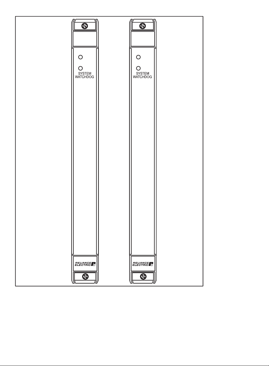
COMMON
MEMORY
MODULE
57C413B
COMMON
MEMORY
MODULE
57C423
BAT.OK
BAT.OK
2Ć2
Figure 2.1 Ć Module Faceplate
Page 11

2.2 Electrical Description
The Common Memory module incorporates the bus arbitration logic
required when there are two or more Processor modules in a rack.
Note that bus arbitration logic is enabled only when the module is in
slot 0. The bus arbitration logic will support up to a maximum of four
Processors located in slots 1Ć4.
The bus arbiter resolves the contention problem that arises when
two or more Processors attempt to access the backplane bus at the
same time. Bus arbitration logic guarantees that every Processor
requesting the bus will be given a turn on the bus before any other
Processor can access it a second time. If two Processors attempt to
use the bus at the same time and neither one has previously
accessed the bus, the Processor module located in the
lowerĆnumbered slot will be permitted to access the bus first.
The superĆcapacitor on the Common Memory module can be
charged to more than 90% of its rated capacity in approximately 8
minutes. It is typically capable of retaining the contents of RAM
memory for approximately 400 minutes should the BAT.OK" light go
out and power is removed from the module. (Removing or replacing
the Common Memory module may affect tasks and variables in the
rack. Appendix E describes the effect on tasks and variables in a
DCS 5000 rack. Appendix F describes the effect on tasks and
variables in an AutoMax rack.)
The module also contains a watchdog timer that is used to detect
Processor failures in a multiĆProcessor system. If a Processor is
unable to reset the watchdog timer, the timer will generate an
interrupt to notify the other Processors in the rack of the failure. A
4.6" will appear on the faceplate of all Processor modules except
the one that timed out. The watchdog timer is enabled only when the
module is in slot 0.
PowerĆup diagnostics for this module are run by a Processor module.
Diagnostics are performed on the RAM memory, control registers,
and watchdog timers.
2Ć3
Page 12

fadfdfdasfdsfdsdsdfdsfdsfdsfsdfdsa
dfdsfdsfdfdsfdsfsadfda
fdfaddfdd
Page 13

3.0 INSTALLATION
This section describes how to install and remove the module and the
onĆboard battery. Note that removing or replacing the Common
Memory module may affect tasks and variables in the rack. Appendix
E illustrates how tasks and variables are affected in a DCS 5000 rack.
Appendix F illustrates how tasks and variables are affected in an
AutoMax rack.
DANGER
THE USER IS RESPONSIBLE FOR CONFORMING TO THE NATIONAL ELECTRIC
CODE AND ALL OTHER APPLICABLE CODES WITH RESPECT TO WIRING,
GROUNDING, DISCONNECTS, AND OVERCURRENT PROTECTION. FAILURE TO
OBSERVE THIS PRECAUTION COULD RESULT IN SEVERE BODILY INJURY OR
LOSS OF LIFE.
3.1 Initial Installation
Use the following procedure to install the module:
Step 1. Turn off power to the rack and all connections.
Step 2. Take the module out of its shipping container. Take it out of
Step 3. Activate the onĆboard battery. When viewing the Common
Step 4. Insert the module into the desired slot in the rack. Use a
the antiĆstatic bag, being careful not to touch the
connectors on the back of the module.
Memory module from the front, you can access the battery
through the opening in the right wall portion of the
protective enclosure. Activate the battery by taking it out of
its holder and removing the tape that covers it. Replace
the battery in its holder. Make certain that the battery is
facing in the proper direction, i.e., the end marked +" on
the battery is facing the end marked +" on the battery
holder. For maximum battery life, you should not remove
the tape from the battery unless you intend to turn power
on to the module immediately.
screwdriver to secure the module into the slot. To enable
bus arbitration logic, the Common Memory module must
be placed in slot 0. For M/N 57C413B, the slot to the right
of the Common Memory module must contain either a
Processor module or be empty because the Common
Memory module takes up two slots of logical address
space. For M/N 57C423, the 3 slots to the right of the
module must contain either a Processor module or be
empty because the module takes up four slots of logical
address space when in slot 0. Refer to figure 3.1.
To serve as data storage, the module must be placed in an
even numbered slot (2,4,6,8,10,12,14). The slot to the right
of the Common Memory module must be empty because
the module (both 57C413B and 57C423) takes up two
slots of logical address space when used in this way.
Refer to figure 3.1.
3Ć1
Page 14

Typical 16 Slot Rack
16
Typical 10 Slot Rack
P/S
0123456789101112131415
Step 5. Turn on power to the rack.
Step 6. Verify the installation. If the Common Memory module was
10
Figure 3.1Ć Rack Slot Numbers
placed in slot 0, the powerĆup diagnostics performed
automatically by a Processor module should verify that the
module is operational.
If the Common Memory module is placed in any even slot
other than 0, it must be manually tested like a standard I/O
module. Connect the personal computer to the system
and run the Programming Executive Software.
Stop all programs that may be running.
Use the I/O MONITOR function and enter the module slot
number and any valid register number (0Ć32767). Also
enter the slot number +1 and any valid register number
(0Ć32767) to test the upper 32K register of memory. Verify
that data can be read from and written to the registers. To
ensure your application task does not access old or
incorrect data, you may want to create a BASIC task to
write zeroes to each register location before you run any
other application tasks. This is only required if you do not
initialize values in your application tasks.
3.2 Module Replacement
Removing or replacing the Common Memory module may affect
tasks and variables in the rack. Before beginning the procedure
below, refer to Appendix E for DCS 5000 racks or Appendix F for
AutoMax racks.
Use the following procedure to replace a module:
Step 1. Stop any application tasks that may be running.
Step 2. Turn off power to the rack and all connections.
Step 3. Use a screwdriver to loosen the screws that hold the
Step 4. Place the module in the antiĆstatic bag it came in, being
3Ć2
module in the rack. Remove the module from the slot in
the rack.
careful not to touch the connectors on the back of the
Page 15

module. Place the module in the cardboard shipping
container.
Step 5. Take the new module out of the antiĆstatic bag, being
Step 6. Activate the battery by taking it out of its holder and
Step 7. Insert the module into the desired slot in the rack. Use a
Step 8. If you are replacing the M/N 57C413 Common Memory
Step 9. Turn on power to the rack.
THE BATTERY USED WITH THIS DEVICE MAY PRESENT A HAZARD IF
MISTREATED. DO NOT RECHARGE, DISASSEMBLE, HEAT ABOVE 100_C
(212_F), INCINERATE, OR SWALLOW. REPLACE BATTERY WITH RELIANCE
ELECTRIC M/N 57C385 ONLY. DISPOSE OF USED BATTERY PROMPTLY.FAILURE
TO OBSERVE THIS PRECAUTION COULD RESULT IN BODILY INJURY.
careful not to touch the connectors on the back of the
module.
removing the tape that covers it. Replace the battery in its
holder. Make certain that the battery is facing in the proper
direction, i.e., the end marked +" on the battery is facing
the end marked +" on the battery holder.
screwdriver to secure the module into the slot.
module that required an external battery backup with M/N
57C413B or 57C423, you may now remove the battery
backup from the power supply. The battery backup is not
required when the Common Memory module is placed in
an AutoMax rack containing Processor models 57C430,
57C431, 57C435 or later. DO NOT REMOVE THE
BATTERY BACKUP FROM RACKS CONTAINING DCS
PROCESSOR M/N 57C407. The external battery is
required to back up this Processor.
WARNING
3.3 OnĆBoard Battery Replacement
See section 5.2 for a list of the possible reasons that the BAT. OK"
light on the faceplate can shut off. If you need to replace the battery,
the superĆcapacitor will typically provide 400 minutes of backĆup
power between the time the BAT.OK" light goes off and power is
removed from the rack, and the time you insert and activate the new
battery.
Note that the superĆcapacitor on the module is charged by the power
supply. Therefore, be sure power has been turned on to the module
for at least 8 minutes to ensure the superĆcapacitor is sufficiently
charged to retain the contents of RAM memory when the battery is
removed.
Use the following procedure to replace the battery on the Common
Memory module.
Step 1. Stop any application tasks that may be running.
Step 2. Turn off power to the system.
Step 3. Loosen the screws that hold the module in the rack.
Remove the module from the slot in the rack, being careful
not to touch the connectors on the back of the module.
3Ć3
Page 16

Step 4. Take the old battery out of the holder. Remove the tape
Step 5. ReĆinsert the module into the correct slot in the rack. Use a
Step 6. Turn on power to the rack. The BAT. OK" LED should be
from the new battery and insert the battery in the holder.
Make certain that the battery is facing the proper direction,
i.e., the end marked +" on the battery is facing the end
marked +" on the battery holder.
screwdriver to secure the module into the rack.
lit.
3Ć4
Page 17

4.0 PROGRAMMING
This section describes how the data is organized in the module and
provides examples of how the module is accessed by the application
software.
The Common Memory module has two distinct modes of operation
depending on the slot that it is in. If the module is located in slot 0,
the bus arbitration logic and watchdog timer are enabled and the
module is controlled entirely by the leftĆmost Processor module. If it is
in any other even slot, the bus arbitration logic and watchdog timer
are disabled and the module provides userĆconfigurable data storage
only. This mode is useful if you need to control explicitly the physical
allocation of memory, e.g., to define consecutive registers for shift
register instructions. Note, however, that it is not possible to define
arrays in this mode.
4.1 Configuration
Before creating AutoMax application tasks, the user must configure
the hardware in the system. Configuration is the process of assigning
variable names to I/O and memory locations in modules located in
the rack. The configuration process makes it possible to create
application tasks that reference variable names instead of fixed
locations. This information must be loaded onto the Processor
modules in the rack before application tasks can run.
This section outlines some basic system parameters that determine
how to configure the Common Memory module and reference
memory stored on the module. Unless specifically noted otherwise,
the information below applies to both M/N 57C413B and M/N 57C423
Common Memory modules as they operate in both DCS 5000 and
AutoMax systems. Recall that when either module is in an even slot
other than 0, only 64K x 16 worth of memory (two logical slots in the
rack) is available for configuration by the user.
4.1.1 Variable Control and Access
To understand the effect of a Common Memory module in a rack, it is
important to understand variable control in AutoMax systems. There
are two types of variable control in AutoMax systems: common and
local. Control" refers to whether the variable will be accessed
exclusively by one application task (local), or whether it must be
accessible for reads or writes by more than one application task in
the rack (common). Defining variable control is accomplished as
follows:
local variable: a) default control type; not defined
in configuration
common variable: a) defined in configuration; there are
two types, memory and I/O. If
memory, can be volatile or
nonĆvolatile
Variable access in an application task is enabled by declaring the
variable common or local in application tasks that reference the
variable. See the appropriate programming language reference
manuals for specific information on declaring variables local or
common.
4Ć1
Page 18

4.1.2 Variable Storage
Local variables are stored on the Processor module in which the
application task that declares them will run. Common variables are
stored on the Processor module, unless there is a Common Memory
module in slot 0 of the rack, in which case the common variables are
stored on the Common Memory module instead. This frees up
memory on the Process module for application tasks. Because
common variables can be stored on either the Processor module or a
Common Memory module if it is located in slot 0, a variable defined
in the configuration and declared common in an application task is
not necessarily one that is stored on the Common Memory module.
In other words, when used to describe a variable in AutoMax,
common" refers strictly to variable control, not to variable storage.
A Common Memory module located in a nonĆ0 slot is treated by the
system as two generic" I/O modules with 32K registers each (32K in
the actual slot location and 32K in the slot to the immediate right).
Because all I/O variables are considered common by the system,
variables defined on this module are treated like any other common
variables for storage purposes: they are stored on the Processor
module in a singleĆProcessor rack, or on the Common Memory
module in slot 0 if it is installed.
When the Common Memory module is in slot 0, the allocation of its
memory is under system control. During configuration, the user
specifies only the name and type (e.g., boolean) of each common
variable. These variables are accessible to application tasks and
Programming Executive functions (e.g., monitoring) by name only.
If the Common Memory module is in any other even slot, memory on
the module is allocated by register/bit address exactly as specified by
the user during configuration. These variables are accessible to
application tasks and Programming Executive functions by name or
register/bit address
4.1.3 Configuration Method
The method used to configure the Common Memory module
depends both upon the Programming Executive software version
being used, and on the slot number (0 or any other even slot) of the
module. For Programming Executive software V3.0 and later, the
module is configured like all other modules, i.e., using the Rack
Configurator menu option. See JĆ3750, the Programming Executive
V3.0 instruction manual for information on configuring the module in
both slot 0 and other even slots.
For Programming Executive software V2.1 and earlier, the Common
Memory module is configured in a special type of application task
called the configuration task, one of which is required per rack. See
Appendix C for detailed instructions on configuring the module if you
are using V2.1 and earlier of the Programming Executive software.
4.2 Restrictions
This section describes limitations and restrictions on the use of this
module.
4Ć2
Page 19

4.2.1 Rack Slot Restrictions
A Common Memory module is required in slot 0 in a rack that
contains more than one Processor module. The slot to the right of the
Common Memory module must either be empty or contain a
Processor module for M/N 57C413B. For M/N 57C423, the 3 slots to
the right of the module must either be empty or contain a Processor
module.
This module may also be plugged into even slots (2,4,6,8,10,12, or
14). Since the 128K bytes (64K registers) of memory available (for
both modules in a nonĆ0 slot) require two slots of address space, the
slot to the right of the Common Memory module must be empty.
4.2.2 Remote Racks
This module cannot be used in a remote I/O rack.
4Ć3
Page 20

fadfdfdasfdsfdsdsdfdsfdsfdsfsdfdsa
dfdsfdsfdfdsfdsfsadfda
fdfaddfdd
Page 21

5.0 DIAGNOSTICS AND
TROUBLESHOOTING
This section explains how to troubleshoot the Common Memory
module.
5.1 The SYSTEM WATCHDOG" LED is Off
Problem: The green SYSTEM WATCHDOG" LED on a Common
Memory module located in slot 0 is off, and a Processor module in
the rack displays codes 4.0 through 4.6. These error codes mean
that the Common Memory module has failed one of its powerĆup
diagnostics.
Systematically swap out the Common Memory module and the
Processor module(s). Make certain power is off before removing any
module from the rack. After each swap, if the problem is not
corrected, replace the original item before going on to the next item.
If the problem persists, take all of the modules except the Common
Memory module and one Processor module out of the rack. If the
problem is now corrected, another module in the rack is causing the
problem. Replace the remaining modules one at a time until the
problem reappears. If none of these tests reveals the problem, try
replacing the backplane.
5.2 The BAT.OK" LED is Off
Problem: The BAT. OK" LED on the Common Memory module
faceplate is off. The possible causes of this problem are the following:
D the tape covering the battery has not been removed
D the battery is not facing in the proper direction
D the battery is missing
D the battery is malfunctioning
D the power supply is malfunctioning
To correct the problem, first turn off power to the rack. Refer to steps
1Ć3 in section 3.3 for instructions on taking the Common Memory
module out of the rack to inspect the battery. If the tape is still
covering the battery, remove it. If the battery is missing or not facing
in the proper direction, insert the battery with the +" end facing the
+" marking on the battery holder. If none of the above actions
correct the problem, replace the battery.
5.3 Incorrect Data
Problem: The output is either always off, always on, or different than
expected. The possible causes of this error are a module in the
wrong slot, a malfunctioning module, or a programming error. Use
the following procedure to isolate the problem:
Step 1. Verify that the module is in the correct slot.
Refer to figure 3.1. Verify that the correct number of slots
to the right of the Common Memory module are either
5Ć1
Page 22

empty or contain a Processor module. If this is not the
case, multiple modules will respond to references.
If the module is not in slot 0, i.e., it is serving as data
storage, verify that the definition statements in the
configuration are associated with the correct slots.
Step 2. Verify that the variables are being referenced correctly.
Verify that all tasks that reference variables on this module
declare them COMMON. Only one task should be writing
to any one variable.
Step 3. Verify that the module can be accessed.
Connect the personal computer to the system and run the
Programming Executive Software.
Stop all programs that may be running.
If the module is in slot 0, use the VARIABLE MONITOR to
read and write to the variable by name. If the variable
cannot be accessed correctly, proceed to step 4.
If the module is in any even slot other than 0, use the I/O
MONITOR to read and write to the desired register. If the
register cannot be accessed correctly, proceed to step 4.
Step 4. Verify that the hardware is working correctly.
Systematically swap out the Common Memory module
and the Processor module(s). Make certain power is off
before removing any module from the rack. After each
swap, if the problem is not corrected, replace the original
item before going on to the next item. If the problem
persists, take all of the modules except one Processor
module and the Common Memory module out of the
backplane. If the problem is now corrected, one of the
other modules in the rack is malfunctioning. Reconnect
the other modules one at a time until the problem
reappears. If none of these tests reveals the problem,
replace the rack/backplane.
5.4 Bus Error
Problem: A 31" or 51" through 58" appears on the Processor
module's LED. This error message indicates that there was a bus
error when the system attempted to access the module. The possible
causes of this error are a missing module, a module in the wrong
slot, or a malfunctioning module. Use the following procedure to
isolate a bus error:
Step 1. Verify that the Common Memory module is in the correct
Step 2. Verify that the module can be accessed.
5Ć2
slot.
If the module is in slot 0, proceed to step 4. If the module
is in any other even slot, proceed to step 2.
Connect the personal computer to the system and run the
Programming Executive Software.
Stop all programs that may be running.
The cause of a 31" error message is most likely an error
in an address calculation performed by an application
Page 23

program. Verify that any IOREAD functions and IOWRITE
statements are using valid addresses.
If IOREAD functions and IOWRITE statements are using
valid addresses or if the error message in question was
51" through 58", use the I/O MONITOR function to
display the registers on the memory module. Remember
to specify the correct logical slot.
If you can monitor the inputs, the problem lies in the
application software (proceed to step 3). If you cannot
monitor the inputs, the problem lies in the hardware
(proceed to step 4).
Step 3. Verify that the variable names are consistent with what is
Step 4. Verify that the hardware is working correctly.
used in the application task.
If you are using the AutoMax Programming Executive
Version 2.1 or earlier, verify that the variables defined by
IODEF and MEMDEF statements in the configuration task
match the variable names used in the application task.
In AutoMax Version 3.0 or later, verify the information on
the Variable Configurator form" (screen) is consistent with
the variable names used in the application task.
Systematically swap out the Common Memory module,
the Processor module(s) and the backplane. Make certain
power is off before removing any module from the rack.
After each swap, if the problem has not been corrected,
replace the original item before swapping out the next
item.
5Ć3
Page 24

fadfdfdasfdsfdsdsdfdsfdsfdsfsdfdsa
dfdsfdsfdfdsfdsfsadfda
fdfaddfdd
Page 25

Appendix A
Technical Specifications
Ambient Conditions
D Storage temperature: -40oCĆ85oC
o
D Operating temperature: 0
D Humidity: 5Ć90% nonĆcondensing
Maximum Module Power Dissipation
D 5.3 Watts
Dimensions
D Height: 11.75 inches
D Width: 1.25 inches
D Depth: 7.375 inches
System Power Requirements
D +5 volts: 1050 mA
Battery Specifications
D Type: Lithium
D Size: AA
D Voltage: 3.6 Volts
D Amp Hrs.: 2.0
CĆ60oC
Memory Retention
D Minimum holdĆup with battery:ă600 days
D Typical holdĆup with battery: 2000 days
D Minimum holdĆup without battery:ă130 minutes
D Typical holdĆup without battery:ă400 minutes
D Maximum chargeĆup time:ă8 minutes
AĆ1
Page 26

fadfdfdasfdsfdsdsdfdsfdsfdsfsdfdsa
dfdsfdsfdfdsfdsfsadfda
fdfaddfdd
Page 27

Appendix B
Module Block Diagram
Common Memory Module (57C413 and 57C423)
Common Memory Module (57C413)
ADDRESS
BUS
BUS
ADDRESS
WDOG OK
BD RESET
INITIALIZE
BYTE HI EN
WRITE MEM
READ MEM
YACK
SYSTEM WATCHDOG INTERRUPT
BUSY
BUS GRANTS
BCLK
BUS REQUESTS
ID BUS
BUS
ADDRESS
DECODER
EVEN
SLOT
CONTROL
LOGIC
DATA
TRANSCEIVERS
BUS
ARBITRATION
SLOT 0
READ
WRITE
BUS CLOCK OK
DIAGNOSTICS OK
MEMORY
64K x 16 = M/N 57C413B
128K x 16 = M/N 57C423
SYSTEM
WATCHDOG
RAM
BATTERY
BACKUP
BAT. OK
SYSTEM
WATCHDOG
BĆ1
Page 28

fadfdfdasfdsfdsdsdfdsfdsfdsfsdfdsa
dfdsfdsfdfdsfdsfsadfda
fdfaddfdd
Page 29

Appendix C
Configuring the Common Memory Module
in DCS 5000 or AutoMax V 2.1
or Earlier Systems
In DCS 5000 or AutoMax Version 2.1 or earlier systems, a configuration task must
be created and loaded onto the Processor(s) in the rack before any application
task can be executed. The configuration task defines all common variables, i.e.,
variables that are accessible to more than one application task in the rack
(physical inputs/outputs and memory variables). The location of the Common
Memory module in the rack determines the type of statement required to define
these variables. This appendix describes the configuration task statements
required to configure the Common Memory module in DCS 5000 or AutoMax 2.1
Systems.
Common Memory Module Located in Slot 0
When the Common Memory module is in slot 0, the allocation of data storage on
the module is automatic and completely under the control of the operating
system. This means you can reserve storage space for the common variable, but
not specify its actual address. You define common variables in the configuration
task by using either the MEMDEF or NVMEMDEF statement. These statements
are described in detail below.
MEMDEF Statement
The MEMDEF statement is used to define common variables that will not retain
their current values in the event of a power loss. On power up, these volatile
variables are set to zero if there is a battery backup. However, if there is no
battery backup, all common data (variables) stored on the Common Memory
module is lost. This statement may be used to define any valid data type, i.e.,
real, integer, double integer, boolean, and string. Common variables can then be
accessed by any task that declares their variable names COMMON.
The following example defines a single precision integer (16 bits) with the name
WINDOW%", and a boolean (1 bit) with the name STOPPB@". Note the
terminating characters are used to specify data type. See JĆ3649 for more
information on data types.
1000 MEMDEF WINDOW%, STOPPB@
The MEMDEF statement also allows you to define array variables. The following
example defines an array of 20 (0-19) singleĆprecision integers with the name
SIZES%".
1650 MEMDEF SIZES%(19)
NVMEMDEF Statement
The NVMEMDEF statement is used to define common variables that will retain
their current value in the event of a power loss i.e., nonĆvolatile variables.
However, if the battery fails, all common data (variables) stored on the Common
Memory module is lost. This statement may be used to define variables of any
valid data type which can be accessed by any task that declares them COMMON.
The following example defines a single precision integer (16 bits) with the name
WINDOW%", and a boolean (1 bit) with the name STOPPB@".
CĆ1
Page 30

Appendix C
(Continued)
1000 NVMEMDEF WINDOW%, STOPPB@
The NVMEMDEF statement also allows you to define array variables. The
following example defines an array of 20 (0Ć19) singleĆprecision integers with the
name SIZES%".
1650 NVMEMDEF SIZES%(19)
Common Memory Module Located in Any
Even Slot Other Than 0
This section describes how to configure the Common Memory module when it is
located in any even slot other than 0. In this situation the Common Memory
module provides userĆconfigurable data storage only. In other words, you can
specify the exact address at which to store data.
The slot to the right of the Common Memory module must be empty because the
module contains 64K userĆconfigurable registers, or the equivalent of the address
space of two slots. Therefore, if the Common Memory module is placed in slot 6,
the first 32K registers are addressed as slot 6. The second 32K registers are
addressed as slot 7. Refer to the figure below.
Register 0 Register 0
SLOT 6 SLOT 7
Common
Memory
Module
Register 32767 Register 32767
64K Registers
(128K Bytes Memory)
Empty
Slot
32 Bit Register Reference Format
Use the following method to reference 32 bits of data as a single value. One
statement is required in the configuration task for each variable. The symbolic
name of each value should be as meaningful as possible:
nnnnn IODEF SYMBOLIC_NAME![ SLOT=s, REGISTER=r]
When referenced as a double precision integer of 32 bits, register r" is the high
order 16 bits and register r+1" is the low order 16 bits.
CĆ2
Page 31

Appendix C
(Continued)
16 Bit Register Reference Format
Use the following method to reference a 16 bit register as a single precision
integer. One statement is required in the configuration task for each variable. The
symbolic name of each value should be as meaningful as possible:
nnnnn IODEF SYMBOLIC_NAME%[ SLOT=s, REGISTER=r]
Bit Reference Format
Use the following method to reference individual bits in a register. One statement
is required in the configuration task for each variable. The symbolic name of each
bit should be as meaningful as possible:
nnnnn IODEF SYMBOLIC_NAME@[ SLOT=s, REGISTER=r, BIT=b]
where:
nnnnn - BASIC statement number. This number may range from 1Ć32767.
SYMBOLIC_NAME! - A symbolic name chosen by the user and ending with (!).
This indicates a double precision, or long integer data type and all references will
access registers r and r+1.
SYMBOLIC_NAME% - A symbolic name chosen by the user and ending with
(%). This indicates a single precision integer data type and all references will
access register r".
SYMBOLIC_NAME@ - A symbolic name chosen by the user and ending with
(@). This indicates a boolean data type and all references will access bit number
b" in register r".
SLOT - Slot number that the module is plugged into. This number may range
from 2-14. If you are referencing registers on the upper half of the card,
remember to use the slot number of the empty slot to the right of the module in
the rack.
REGISTER - Specifies the register that is being referenced. This number may
range from 0Ć32767 for both slots.
BIT - Used with boolean data types only. Specifies the bit in the register that is
being referenced. This number may range from 0Ć15.
Examples of Configuration Statements
The following statement assigns the symbolic name WINDOW! to register 2000
and 2001 on the memory module located in slot 10:
1000 IODEF WINDOW![ SLOT=10, REGISTER=2000]
The following statement assigns the symbolic name
POSITION% to register 250 of the input module located in slot 4:
1020 IODEF POSITION%[ SLOT=4, REGISTER=250]
The following statement assigns the symbolic name LIGHT@ to bit 9 of register
10 on the input module located in slot 6:
2050 IODEF LIGHT@[ SLOT=6, REGISTER=10, BIT=9]
CĆ3
Page 32

fadfdfdasfdsfdsdsdfdsfdsfdsfsdfdsa
dfdsfdsfdfdsfdsfsadfda
fdfaddfdd
Page 33

Appendix D
Summary of Common
Memory Module Features
M/N 57C413
This module has 128K bytes of memory and requires external battery backup
(M/N 57C492) to mainain the contents of memory in the event of a power failure.
M/N 57C413B
This module has 128K bytes of memory and an onĆboard lithium battery to
maintain the contents of memory in the event of a power failure.
M/N 57C423
This module has 256K bytes of memory available when plugged into slot 0, and
128K bytes available when plugged into any other nonĆzero slot. An onĆboard
lithium battery maintains the contents of memory in the event of a power failure.
This module is supported only by the following Program Executive version: 2.1E,
and 3.1C and later.
DĆ1
Page 34

fadfdfdasfdsfdsdsdfdsfdsfdsfsdfdsa
dfdsfdsfdfdsfdsfsadfda
fdfaddfdd
Page 35

Appendix E
How Removing/Replacing The Common
Memory Module Affects Tasks and
Variables in a DCS 5000 Rack
The following tables illustrate how removing or replacing the Common Memory
module affects tasks and variables in a DCS 5000 rack. (Refer to Appendix F for
information regarding the effect on tasks and variables in an AutoMax rack.) In
each case, assume a BASIC task has written to variables in both the Processor
(local) and the Common Memory module (common). Also assume the task was
stopped before power was removed from the rack.
The following information applies only if an external battery backup (57C492) is
connected to the power supply. The external battery backup is required for DCS
5000 Processor memory backup. If the battery backup is not used, all tasks are
deleted when power is removed from the rack.
Common Memory Module Located In Slot 0
For the following, assume the Common Memory module is in slot 0 and a
Processor module is in slot 1.
Status of Data
Common
Action
Replace 57C413A with
Same or new 57C413A
ąAt power up
Replace 57C413A with
New 57C413B or 57C423
ąAt power up
Replace 57C413B or
57C423 with new or used
57C413B or 57C423
(module may contain data
from another application)
ąAt power up
Replace battery on
57C413B or 57C423 and
return same module to
rack
ąAt power up***
App.
Ta s k
Deleted?
YES* N/A N/A N/A N/A
NO UNINSTALLED* N/A N/A N/A
NO STOP Data OK Zero Data OK
App.
Ta s k
Status
Error Code 13 appears on Processor LEDs**
NonVol Vol Local
* You must reĆload the configuration and application tasks onto the rack. This
procedure is described in the Programming Executive instruction manual
(JĆ3630).
** Select DOWNLOAD from the ON LINE menu to download the configuration
and application tasks. Select ERROR CLEAR to clear the LED fault code on
the Processor module. Refer to JĆ3630 for more information about the ON
LINE menu.
*** Assumes superĆcapacitor has maintained memory on the module during the
time required to replace the battery.
EĆ1
Page 36

Appendix E
(Continued)
The Common Memory Module Is In Any
Even Slot Other Than 0
In the following, assume the Common Memory module is in slot 2 and the single
Processor module in the rack is in slot 1. Recall that in this configuration, common
variables, as well as local variables, are being stored on the Processor module.
Status of Data
Common
Action
Replace 57C413A with
Same or new 57C413A
ąAt power up
Replace 57C413A with
New 57C413B or
57C423
ąAt power up
Replace 57C413A with
programmed 57C413B
or 57C423 (module may
contain data from
another application)
ąAt power up
Replace 57C413B or
57C423 with New
57C413B or 57C423
ąAt power up
Replace 57C413B or
57C423 with proĆ
grammed 57C413B or
57C423 (module may
contain data from
another application)
ąAt power up
Replace battery on
57C413B or 57C423 and
return same module to
rack
ąAt power ***
App.
Ta s k
Deleted?
NO STOP Data OK Zero Lost
NO STOP Data OK Zero Zero* Data OK
NO STOP Data OK Zero Value from
NO STOP Data OK Zero Zero* Data OK
NO STOP Data OK Zero Data OK Data OK
App.
Ta s k
Status
NonVol Vo l I/O Local
(Random)
programmed
module at
same
address*
Error Code 13 appears on Processor LEDs**
Data OK
Data OK
* To ensure your application task does not access old or incorrect data, create
a BASIC task to write zeroes to each register location before you run any
other application tasks.
** Select DOWNLOAD from the ON LINE menu to download the configuration
and application tasks. Select ERROR CLEAR to clear the LED fault code on
the Processor module. Refer to JĆ3630 for more information about the ON
LINE menu.
*** Assumes superĆcapacitor has maintained memory on the module during the
time required to replace the battery.
EĆ2
Page 37

Appendix F
How Removing/Replacing The Common
Memory Module Affects Tasks and
Variables in an AutoMax Rack
The following tables illustrate how removing or replacing the Common Memory
module affects tasks and variables in an AutoMax rack. (Refer to Appendix E for
information regarding the effect on tasks and variables in a DCS 5000 rack.) In
each case, assume a BASIC task has written to variables in both the Processor
(local) and the Common Memory module (common). Also assume the task was
stopped before power was removed from the rack.
Common Memory Module Located In Slot 0
For the following, assume the Common Memory module is in slot 0 and a
Processor module is in slot 1.
Status of Data
Common
Action
Replace 57C413A with
Same or new 57C413A
ąAt power up
Replace 57C413A with
New 57C413B or 57C423
ąAt power up
Replace 57C413B or
57C423 with new or used
57C413B or 57C423 (modĆ
ule may contain data from
another application)
ąAt power up
Replace battery on
57C413B or 57C423 and
return same module to
rack
ąAt power up**
App.
Ta s k
Deleted?
YES* N/A N/A N/A N/A
YES* N/A N/A N/A N/A
YES* N/A N/A N/A N/A
NO STOP Data OK Zero Data OK
App.
Ta s k
Status
NonVol Vol Local
* You must reĆload the configuration and application tasks onto the rack. This
procedure is described in the AutoMax Programming Executive instruction
manual. Refer JĆ3750 if you are using AutoMax Version 3.0 or later. Refer to
JĆ3684 if you are using AutoMax Version 2.1 or earlier.
** Assumes superĆcapacitor has maintained memory on the module during the
time required to replace the battery.
FĆ1
Page 38

Appendix F
(Continued)
The Common Memory Module Is In Any
Even Slot Other Than 0
In the following, assume the Common Memory module is in slot 2 and the single
Processor module in the rack is in slot 1. Recall that in this configuration, common
variables, as well as local variables, are being stored on the Processor module.
Status of Data
Common
Action
Replace 57C413A with
Same or new 57C413A
ąAt power up
Replace 57C413A with
New 57C413B or
57C423
ąAt power up
Replace 57C413A with
used 57C413B or
57C423 (module may
contain data from
another application)
ąAt power up
Replace 57C413B or
57C423 with New
57C413B
ąAt power up
Replace 57C413B or
57C423 with used
57C413B or 57C423
(module may contain
data from another
application)
ąAt power up
Replace battery on
57C413B or 57C423 and
return same module to
rack
ąAt power up***
App.
Ta s k
Deleted?
NO STOP Data OK Zero Lost
NO STOP Data OK Zero Zero* Data OK
NO STOP Data OK Zero Value from
NO STOP Data OK Zero Zero* Data OK
NO STOP Data OK Zero
NO STOP Data OK Zero Data OK Data OK
App.
Ta s k
Status
NonVol Vo l I/O Local
(Random)
programmed
module at
same
address*
Value from
used module
at same
address*
Data OK
Data OK
Data OK
* To ensure your application task does not access old or incorrect data, create
a BASIC task to write zeroes to each register location before you run any
other application tasks.
** Assumes superĆcapacitor has maintained memory on the module during the
time required to replace the battery.
FĆ2
Page 39

fadfdfdasfdsfdsdsdfdsfdsfdsfsdfdsa
dfdsfdsfdfdsfdsfsadfda
fdfaddfdd
Page 40

Publication J-3636-2 - May 1992
Copyright © 2002 Rockwell Automation, Inc.. All rights reser ved. Printed in U.S.A.
 Loading...