

Page 1

2-Axis Servo Module
M/N 57C422B
Instruction Manual
J-3642-7
Page 2

The information in this manual is subject to change without notice.
WARNING
THIS UNIT AND ITS ASSOCIATED EQUIPMENT MUST BE INSTALLED,
ADJUSTED AND MAINTAINED BY QUALIFIED PERSONNEL WHO ARE
FAMILIAR WITH THE CONSTRUCTION AND OPERATION OF ALL
EQUIPMENT IN THE SYSTEM AND THE POTENTIAL HAZARDS INVOLVED.
FAILURE TO OBSERVE THESE PRECAUTIONS COULD RESULT IN BODILY
INJURY
WARNING
INSERTING OR REMOVING THIS MODULE OR ITS CONNECTING CABLES
MAY RESULT IN UNEXPECTED MACHINE MOTION. POWER TO THE
MACHINE SHOULD BE TURNED OFF BEFORE INSERTING OR REMOVING
THE MODULE OR ITS CONNECTING CABLES. FAILURE TO OBSERVE THESE
PRECAUTIONS COULD RESULT IN BODILY INJURY.
CAUTION
THIS MODULE CONTAINS STATIC-SENSITIVE COMPONENTS. CARELESS
HANDLING CAN CAUSE SEVERE DAMAGE.
DO NOT TOUCH THE CONNECTORS ON THE BACK OF THE MODULE. WHEN
NOT IN USE, THE MODULE SHOULD BE STORED IN AN ANTI-STATIC BAG.
THE PLASTIC COVER SHOULD NOT BE REMOVED. FAILURE TO OBSERVE
THIS PRECAUTION COULD RESULT IN DAMAGE TO OR DESTRUCTION OF
THE MATERIAL.
WARNING
RELIANCE STRONGLY RECOMMENDS THE USE OF AN EXTERNAL,
HARDWIRED EMERGENCY STOP CIRCUIT THAT WILL DISABLE THE
SYSTEM IN CASE OF IMPROPER OPERATION. UNCONTROLLED MACHINE
OPERATION MAY RESULT IF THIS PROCEDURE IS NOT FOLLOWED.
FAILURE TO OBSERVE THIS PRECAUTION COULD RESULT IN BODILY
INJURY OR DAMAGE TO EQUIPMENT
Rellance® and AutoMax@ are trademarks of Reliance Electric Company or its
subsidiaries.
Rellance™ is a registered trademark of Reliance Electric Company or its subsidiaries.
Page 3

Table Of Contents
1.0 Introduction......................................................................1-1
2.0 Mechanical/Electrical Description..................................2-1
2.1 Mechanical Description............................................2-1
2.2 Electrical Description ...............................................2-3
3.0 Installation........................................................................3-1
3.1 Wiring.......................................................................3-1
3.2 Initial Installation ......................................................3-1
3.3 Module Replacement.............................................3-11
4.0 Programming....................................................................4-1
4.1 Configuration ...........................................................4-2
4.2 Register 0: Encoder Setup.......................................4-3
4.3 Register 1: Drive Setup............................................4-4
4.4 Register 2: Switch Setup .........................................4-5
4.5 Register 3: Proportional Gain ..................................4-7
4.6 Register 4: Integral Gain..........................................4-7
4.7 Register 5: Velocity Gain.........................................4-7
4.8 Register 6: Feedforward Gain..................................4-8
4.9 Register 7: Deadband Compensation......................4-8
4.10 Register 8: Maximum Position Error........................4-9
4.11 Register 9: Maximum Velocity Error........................4-9
4.12 Register 10: In-Position Tolerance ........................4-10
4.13 Registers 11, 12: Positive Overtravel Limit............4-10
4.14 Registers 13, 14: Negative Overtravel Limit ..........4-11
4.15 Registers 15,16: Low Speed
Homing Reference.................................................4-11
4.16 Registers 17,18: Command Position .....................4-12
4.17 Registers 19, 20: Command Velocity ............. .......4-13
4.18 Registers 21, 22: Command Acceleration .............4-13
4.19 Registers 23, 24: Command Deceleration.............4-14
4.20 Registers 25, 26: Gear Ratio.......................... .......4-15
4.21 Register 27: User LEDs.........................................4-15
4.22 Register 28: Direct Drive Reference
Command..............................................................4-16
Note: Register descriptions for equivalent X and Y axis
registers are exactly the same. Although sections of
Chapter 4 are titled by X axis register number, the
equivalent Y register is given in the figure that
accompanies each register description.
I
Page 4

4.23 Registers 29, 30: Sync Position ............................ 4-16
4.24 Register 31: Maximum Voltage Reference ........... 4-17
4.25 Register 32: Positive Linearization Constant ........ 4-18
4.26 Register 33: Negative Linearization Constant....... 4-18
4.27 Registers 34,35: Feedback Unwind Constan........ 4-19
4.28 Registers 36, 37: Gearing Unwind Constant......... 4-19
4.29 Register 38: Gearing Modes, Ratio Format,
Ramp Velocity Control .......................................... 4-20
4.30 Registers 39, 40: Backlash Compensation ........... 4-21
4.31 Register 41: Registration Input
Edge Detection...................................................... 4-22
4.32 Register 63: Auto-Acknowledge............................ 4-22
4.33 Register 64: Interrupt Reset.................................. 4-23
4.34 Register 65: Mode................................................. 4-23
4.35 Register 66: Command ......................................... 4-27
4.36 Register 67: Command ......................................... 4-32
4.37 Register 72: Status................................................ 4-34
4.38 Register 73: Fault.................................................. 4-37
4.39 Registers 74, 75: Current Feedback Position ....... 4-38
4.40 Registers 76, 77: Current Gearing Position .......... 4-39
4.41 Registers 78, 79: Current Velocity ........... ....... ...... 4-39
4.42 Register 80: Following Error.................................. 4-39
4.43 Register 81: Velocity Error .................................... 4-40
4.44 Register 82: Digital Input Status............................ 4-40
4.45 Register 83: Current Velocity Status
Update Period ....................................................... 4-41
4.46 Registers 84, 85: Feedback
Registration Position ............................................. 4-41
4.47 Registers 86, 87: Gearing
Registration Position ............................................. 4-41
4.48 Registers 99-103: Software Version Number........ 4-42
4.49 Interrupt Registers................................................. 4-42
4.49.1 Registers 68/69: Interrupt Enable.............. 4-43
4.49.2 Registers 104/105: Interrupt Source.......... 4-45
4.49.3 Register 4095: Interrupt Status and Control
(ISCR) Register ......................................... 4-47
4.49.4 Sample Application Task with Interrupt ..... 4-48
Note: Register descriptions for equivalent X and Y axis
registers are exactly the same. Although sections of
Chapter 4 are titled by X axis register number, the
equivalent Y register is given in the figure that
accompanies each register description.
I
Page 5

4.50 Cam Registers.......................................................4-49
4.50.1 Register 125: Master Axis
Position Increment .....................................4-53
4.50.2 Registers 126, 127: Master Reference
Position ......................................................4-53
4.50.3 Register 128: Number of Points
in Cam Table..............................................4-54
4.50.4 Register 129:Time Between Points in
Cam Table .................................................4-54
4.50.5 Register 130: Cam Mode ...........................4-54
4.50.6 Register 131: Loop Back
Point in Cam Table ....................................4-56
4.50.7 Cam Data Registers...................................4-57
5.0 Applying the Module........................................................5-1
5.1 Required System Information..................................5-1
5.2 Tuning......................................................................5-1
5.2.1 Auto-Tuning .................................................5-2
5.2.2 Manual Tuning .............................................5-2
5.3 Initialization..............................................................5-5
5.4 Homing ....................................................................5-6
5.5 Moving.....................................................................5-7
5.6 Electronic Gearing ...................................................5-8
5.7 Velocity.............. ...... ....... ...... ....... ...... ....... ...... .........5-9
5.8 Cam Mode.............................................................5-10
6.0 Restrictions ......................................................................6-1
6.1 Remote Racks.........................................................6-1
Note: Register descriptions for equivalent X and Y axis
registers are exactly the same. Although sections of
Chapter 4 are titled by X axis register number, the
equivalent Y register is given in the figure that
accompanies each register description.
III
Page 6

Appendix A
Technical Specifications ...................................................A-1
Appendix B
Module Block Diagram ......................................................B-1
Appendix C
Field Connections..............................................................C-1
Appendix D
Related Components.........................................................D-1
Appendix E
Register Summary.............................................................E-1
Appendix F
Enhancements................................................................... F-1
Appendix G
Compatibility with Earlier Versions .............. ...... ....... ...... .. G - 1
Appendix H
Configuration Task Sample...............................................H-1
Appendices
Appendix I
Digital Servo Loop Block Diagram...................................... I-1
IV
Page 7

List of Figures
Figure 2.1 - Module Faceplate......................................................2-2
Figure 2.2 - Encoder Input Circuit .................................................2-4
Figure 2.3 - Typical Registration Input Circuit...............................2-5
Figure 2.4 - Typical Digital Input Circuit ........................................2-5
Figure 3.1 - Rack Slot Numbers....................................................3-2
Figure 3.2 - Typical Encoder Connections....................................3-3
Figure 3.3 - Typical Encoder Power Supply Connections.............3-4
Figure 3.4 - Typical Limit Switch Connections ..............................3-5
Figure 3.5 - Typical Registration Input Connections .....................3-5
Figure 3.6 - Typical Drive Reference / Voltage Reference
Connections with External P/S..................................3-6
Figure 3.7 - Typical E-stop Circuit with Watchdog Output ............3-7
Figure 3.8 - Typical Drive Fault Connections................................3-8
Figure 4.1 - Encoder Configuration Register.................................4-3
Figure 4.2 - Control Loop Configuration Register .........................4-4
Figure 4.3 - Home and Overtravel Configuration Register............4-5
Figure 4.4 - Proportional Gain Register ........................................4-7
Figure 4.5 - Integral Gain Register................................................4-7
Figure 4.6 - Velocity Gain Register ...............................................4-8
Figure 4.7 - Feedforward Gain Register........................................4-8
Figure 4.8 - Deadband Compensation Register............................4-8
Figure 4.9 - Maximum Position Error ............................................4-9
Figure 4.10 - Maximum Velocity Error Register..............................4-9
Figure 4.11 - In-Position Tolerance Register ................................4-10
Figure 4.12 - Positive Overtravel Limit Registers..........................4-10
Figure 4.13 - Negative Overtravel Limit Registers........................4-11
Figure 4.14 - Low Speed Homing Reference Register .................4-11
Figure 4.15 - Command Position Registers .................................4-12
Figure 4.16 - Command Velocity Registers ..................................4-13
Figure 4.17 - Command Acceleration Registers...........................4-14
Figure 4.18 - Command Deceleration Registers...........................4-14
Figure 4.19 - Gear Ratio Registers ...............................................4-15
Figure 4.20 - User-Controlled LED Register.................................4-16
Figure 4.21 - Drive Command Reference Register.......................4-16
Figure 4.22 - Sync Position Registers...........................................4-17
Figure 4.23 - Maximum Voltage Reference Output Register........4-18
Figure 4.24 - Positive Linearization Constant Register.................4-18
Figure 4.25 - Positive Linearization Constant Register.................4-19
Figure 4.26 - Feedback Unwind Constant Registers ...................4-19
V
Page 8

Figure 4.27 - Gearing Unwind Constant Registers....................... 4-20
Figure 4.28 - Gearing Mode, Ratio Format, and Ramp
Velocity Control Register........................................ 4-20
Figure 4.29 - Backlash Compensation Registers ......................... 4-22
Figure 4.30 - Registration Edge Detection Register..................... 4-22
Figure 4.31 - Auto-Acknowledge Register.................................... 4-23
Figure 4.32 - Interrupt Reset Register.......................................... 4-23
Figure 4.33 - Mode Register......................................................... 4-24
Figure 4.34 - Command Register 66............................................ 4-28
Figure 4.35 - Command Register 67............................................ 4-33
Figure 4.36 - Status Register........................................................ 4-34
Figure 4.37 - Fault Register.......................................................... 4-37
Figure 4.38 - Current Feedback Position Registers ..................... 4-38
Figure 4.39 - Current Gearing Position Registers ........................ 4-39
Figure 4.40 - Current Velocity Registers ...................................... 4-39
Figure 4.41 - Following Error Register.......................................... 4-40
Figure 4.42 - Velocity Error Register............................................ 4-40
Figure 4.43 - Digital Input Status Register.................................... 4-40
Figure 4.44 - Current Velocity Status Update Period Register..... 4-41
Figure 4.45 - Feedback Registration Position Regiesters ............ 4-41
Figure 4.46 - Gearing Registration Position Registers................. 4-42
Figure 4.47 - Software Version Registers..................................... 4-42
Figure 4.48 - Interrupt Enable Masking Register (Status) ............ 4-44
Figure 4.49 - Interrupt Enable Masking Register (Fault) .............. 4-45
Figure 4.50 - Interrupt Source Register (Status) .......................... 4-46
Figure 4.51 - Interrupt Source Register (Fault)............................. 4-47
Figure 4.52 - Interrupt Status and Control Register...................... 4-47
Figure 4.53 - Master Axis Position Increment Register................ 4-53
Figure 4.54 - Master Regference Position.................................... 4-54
Figure 4.55 - Cam Profile Registers............................................. 4-56
Figure 4.56 - Cam Loop Back Register........................................ 4-57
Figure 4.57 - Time Cam Data Registers....................................... 4-58
Figure 4.58 - Position Cam Data Registers.................................. 4-58
VI
Page 9

CHAPTER 1
INTRODUCTION
The 2-Axis Servo Module, in conjunction with external motor
drive systems and electronic encoders, provides two axes of
closed loop point-to-point position, velocity, and acceleration
control. In addition, electronic gearing and electronic cam
allow the module to replace mechanical gear trains and
cams electronically for improved performance with no wear,
no backlash, and faster setup times. Two or more modules
can be connected together to provide synchronized control of
multiple axes.
Typically, this module is used for velocity control,
point-to-point positioning control, electronic line shaft
applications, and electronic cams requiring position
synchronization. See Appendix I for a software block
diagram of the module.
This manual describes the functions and specifications of the
module. It also includes a detailed overview of installation
and servicing procedures, as well as examples of
programming methods. See Appendix F for a list of
enhancements to the current version of the module.
Related publications that may be of interest:
• J-3675 AutoMax ENHANCED BASIC LANGUAGE
• J-3676 AutoMax CONTROL BLOCK LANGUAGE
• J-3677 AutoMax LADDER LOGIC LANGUAGE
• J-36 84 RESO URCE AutoMa x PROGRAMMIN G
• J-3675 AutoMax PROGRAMMING EXECUTIVE
INTRODUCTION
INSTRUCTION MANUAL
INSTRUCTION MANUAL
INSTRUCTION MANUAL
EXECUTIVE INSTRUCTION MANUAL VERSION 2.0
INSTRUCTION MANUAL VERSION 3.0
1-1
Page 10

• IEEE-518 GUIDE FOR THE INSTALLATION OF
ELECTRICAL EQUIPMENT TO MINIMIZE
ELECTRICAL NOISE INPUTS TO CONTROLLERS
FROM EXTERNAL SOURCES
1-2
2-Axis Servo Module M/N 57C422B
Page 11

CHAPTER 2
MECHANICAL /
ELECTRICAL
DESCRIPTION
The following is a description of the faceplate LEDs, field
termination connectors and electrical characteristics of the
field connections.
2.1 Mechanical Description
The 2-Axis Servo module is a printed circuit board assembly
that plugs into the backplane of the DCS 5000/AutoMax rack.
It consists of the printed circuit board, a faceplate, and a
protective enclosure. The faceplate contains tabs at the top
and bottom to simplify removing the card from the rack.
Assembly dimensions are listed in Appendix A.
The faceplate of the module contains a 37-pin D-shell
connector socket and eight LED status indicators for each
axis. It also contains three LEDs that can be controlled from
the application software. Refer to figure 2.1.
MECHANICAL / ELECTRICA L DESCRIPTION
2-1
Page 12
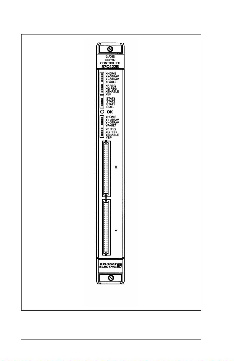
Figure 2.1 – Module Faceplate
2-2
2-Axis Servo Module M/N 57C422B
Page 13

Signals are brought into the module via a multi-conductor
cable (M/N 57C377). One end of this cable attaches to the
faceplate connector, while the other end of the cable
attaches to a terminal board for easy wiring.
On the back of the module are two edge connectors that
attach to the system backplane.
2.2 Electrical Description
The module contains an 80186 microprocessor, local RAM,
and EPROM for the axis software. It also contains a dual port
memory organized as 4k x 16 for transferring data to/from
the module and the application software. Refer to the block
diagram in Appendix B.
This module also contains a watchdog timer that is used to
detect a processor failure. The processor is required to keep
resetting the watchdog before it expires. If the watchdog
expires, the processor will be halted, the green LED on the
faceplate of the module will be turned off, and dual port
memory will be locked so that the module can no longer be
accessed by application software.
M/N 57C422A and later versions of the module support
level-sensitive hardware interrupts. Interrupts are used to
trigger execution of some part of an application task and are
implemented using BASIC language hardware EVENT
statements. See Section 4.49 for more information.
Each of the two axes contain the necessary circuitry for two
encoders. One encoder is used to provide feedback to the
axis. The other encoder can be used when gearing or cam
mode is selected to provide a reference for that same axis.
Each encoder input channel has the necessary circuitry for
an “A” channel, "B" channel, and "Z" channel. The encoder
input circuit is designed for 5 volt differential signals. A single
external power supply is required to power all of the
encoders connected to the module. Refer to figure 2.2 for a
typical encoder input circuit.
MECHANICAL / ELECTRICA L DESCRIPTION
2-3
Page 14
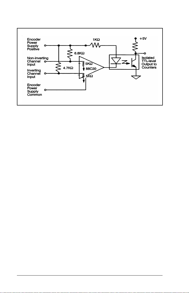
Figure 2.2 – Encoder Input Circuit
Each axis contains two registration inputs which are
connected to faceplate LEDs. One input is used with the
feedback encoder; the other is used with the gearing
reference. These registration inputs are typically used to
strobe the feedback and/or the reference position into a
group of registers for use by application software which can
synchronize the axis to an external event. The input may be
15-24 VDC only and there is a transport delay of
approximately 25 microseconds from the time that a
registration input is asserted until the isolated signal changes
state. Refer to figure 2.3 for a typical input circuit. In critical
applications, hard-wire your overtravel L/S into the
emergency stop circuit so that the drive will be disabled
regardless of the state of the control.
2-4
2-Axis Servo Module M/N 57C422B
Page 15
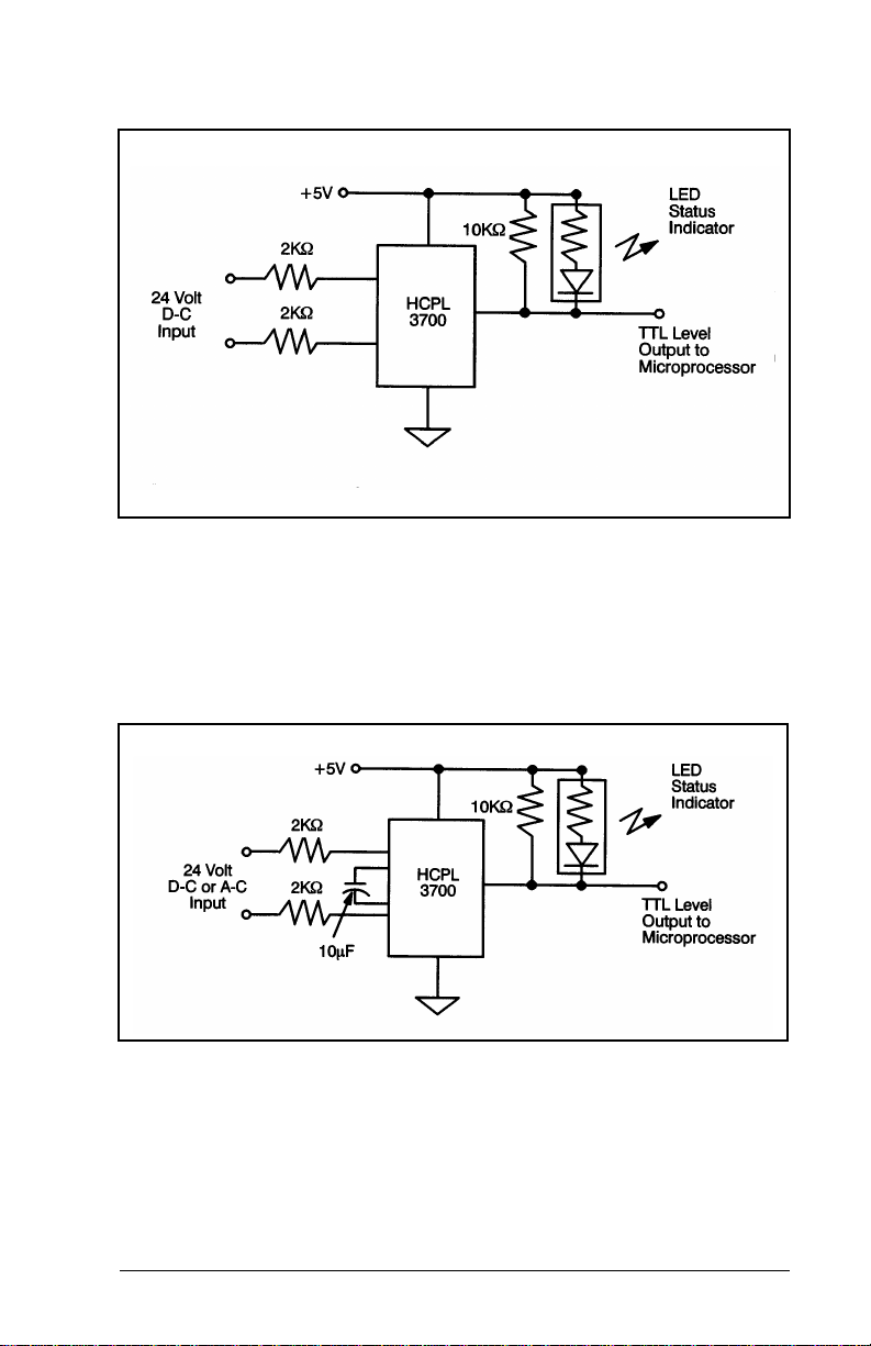
Figure 2.3 – Typical Registration Input Circuit
Each axis on the module contains digital inputs for the home
L/S, drive fault, positive overtravel L/S, and negative
overtravel L/S. These inputs are connected to faceplate
LEDs. Each of the inputs has a 30 Hz filter and may be 24
volts A-C or D-C. Refer to figure 2.4 for a typical input circuit.
Figure 2.4 – Typical Digital Input Circuit
Each axis contains a watchdog output which can be used by
the module to disable the drive if the module falls. The
watchdog output is a normally open relay contact. See figure
3-7.
MECHANICAL / ELECTRICA L DESCRIPTION
2-5
Page 16

In order to provide a current or velocity reference to the servo
drive panel, each axis on the module contains a voltage
output. The voltage output has a range of +
requires an externally mounted +
12 or +15 volt power
10 Volts and
supply. The voltage output is separately isolated for each
channel. Refer to figure 3.6 for a typical output circuit and
isolated power supply connections
2-6
2-Axis Servo Module M/N 57C422B
Page 17

CHAPTER 3
INSTALLATION
This section describes how to install and remove the module
and its cable assembly.
WARNING
THE MACHINERY BUILDER AND/OR USER ARE
RESPONSIBLE FOR INSURING THAT ALL DRIVE TRAIN
MECHANISMS, THE DRIVEN MACHINE, AND PROCESS
MATERIAL ARE CAPABLE OF SAFE OPERATION AT THE
MAXIMUM SPEED AT WHICH THE MACHINE WILL OPERATE.
FAILURE TO OBSERVE THESE PRECAUTIONS COULD
RESULT IN BODILY INJURY
3.1 Wiring
DANGER
THE USER IS RESPONSIBLE FOR CONFORMING WITH THE
NATIONAL ELECTRICAL CODE AND ALL OTHER
APPLICABLE LOCAL CODES. WIRING PRACTICES,
GROUNDING, DISCONNECTS, AND OVERCURRENT
PROTECTION ARE OF PARTICULAR IMPORTANCE. FAILURE
TO OBSERVE THESE PRECAUTIONS COULD RESULT IN
SEVERE BODILY INJURY OR LOSS OF LIFE.
To reduce the possibility of electrical noise interfering with
the proper operation of the control system, exercise care
when installing the wiring from the system to the external
devices. For detailed recommendations refer to IEEE 518.
3.2 Initial Installation
Use the following procedure to install the module:
Step 1. Turn off power to the system. All power to the rack
as well as all power to the wiring leading to the
module, servo, and encoders must be off.
INSTALLATION
3-1
Page 18
DANGER
EQUIPMENT IS AT LINE VOLTAGE WHEN A-C POWER IS
CONNECTED TO THE DRIVE. ALL UNGROUNDED
CONDUCTORS OF THE A-C POWER LINE MUST BE
DISCONNECTED BEFORE IT IS SAFE TO TOUCH ANY
INTERNAL PARTS OF THIS EQUIPMENT. FAILURE TO
OBSERVE THESE PRECAUTIONS COULD RESULT IN
SEVERE BODILY INJURY OR LOSS OF LIFE.
Step 2. Take the module out of its shipping container.
Take the module out of the anti-static bag it came
in, being careful not to touch the connectors on
the back of the module.
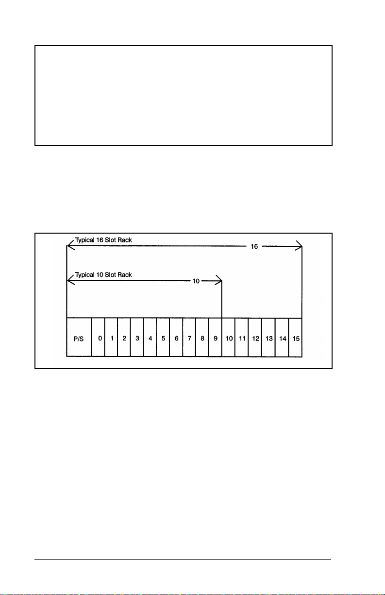
Step 3. Insert the module into the desired slot in the rack.
Refer to figure 3.1.
Figure 3.1 – Rack Slot Numbers
Step 4. Mount the terminal strips (M/N 57C377) on a
panel. The terminal strips should be mounted to
permit easy access to the screw terminals. Make
certain that the terminal strips are close enough to
the rack so that the cable will reach between the
terminal strips and the module.
Step 5. Verify that the feedback encoder has been
mounted on the back of the servo motor. Make
certain that the mechanical coupling between the
motor and encoder is securely fastened. If the
encoder is not mounted directly on the motor,
satisfactory performance may not be achievable.
3-2
2-Axis Servo Module M/N 57C422B
Page 19
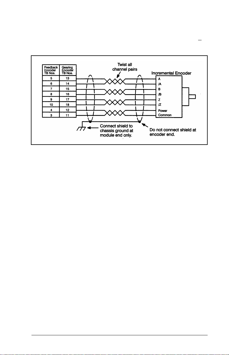
Fasten the field wires from the encoder to the
terminal strip. Typical field connections are shown
in figure 3.2. If you are not using the marker pulse
in your application, you can leave the "Z" and "Z
inputs disconnected.
Figure 3.2 – Typical Encoder Connections
Use twisted pair cabling, connected as shown in
figure 3.2, for the cabling between the encode r
and the terminal strip. If you use cabling with less
than 2 twists/inch, it should be shielded. Note that
the shield should only be connected at one end.
"
Step 6. Mount the external 5 volt power supply for the
INSTALLATION
If a feedback encoder is connected to the gearing
reference of another axis, jumper the connections
on the terminal strip.
encoders. The current rating must be sufficient for
all of the encoders that will be powered from the
supply as well, as the module. Check the
specifications of the encoder you will be using.
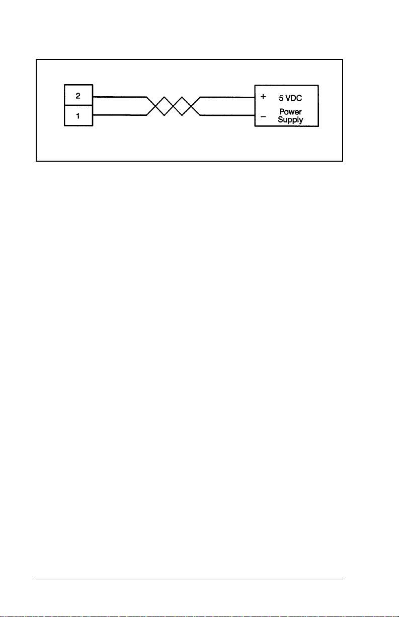
Fasten the field wires from the power supply to the
terminal strip. Typical field connections are shown
in figure 3.3
3-3
Page 20
.
Figure 3.3 – Typical Encoder Power Supply Connection
Use twisted pair cabling, connected as shown in
figure 3.3, for the cabling between the power
supply and the terminal strip. If you use cabling
with less than 2 twists/inch, it should be shielded.
Note that the shield should only be connected at
one end.
For best results, the power supply voltage should
be adjusted to provide 5 volts at the furthest
encoder.
Step 7. If your application requires them, mount the home
L/S, positive overtravel L/S, and negative
overtravel L/S on your machine. Overtravel L/S
should be normally closed devices. Fasten the
field wires from the limit switches to the terminal
strip. Typical field connections are shown in figure
3.4.
3-4
2-Axis Servo Module M/N 57C422B
Page 21
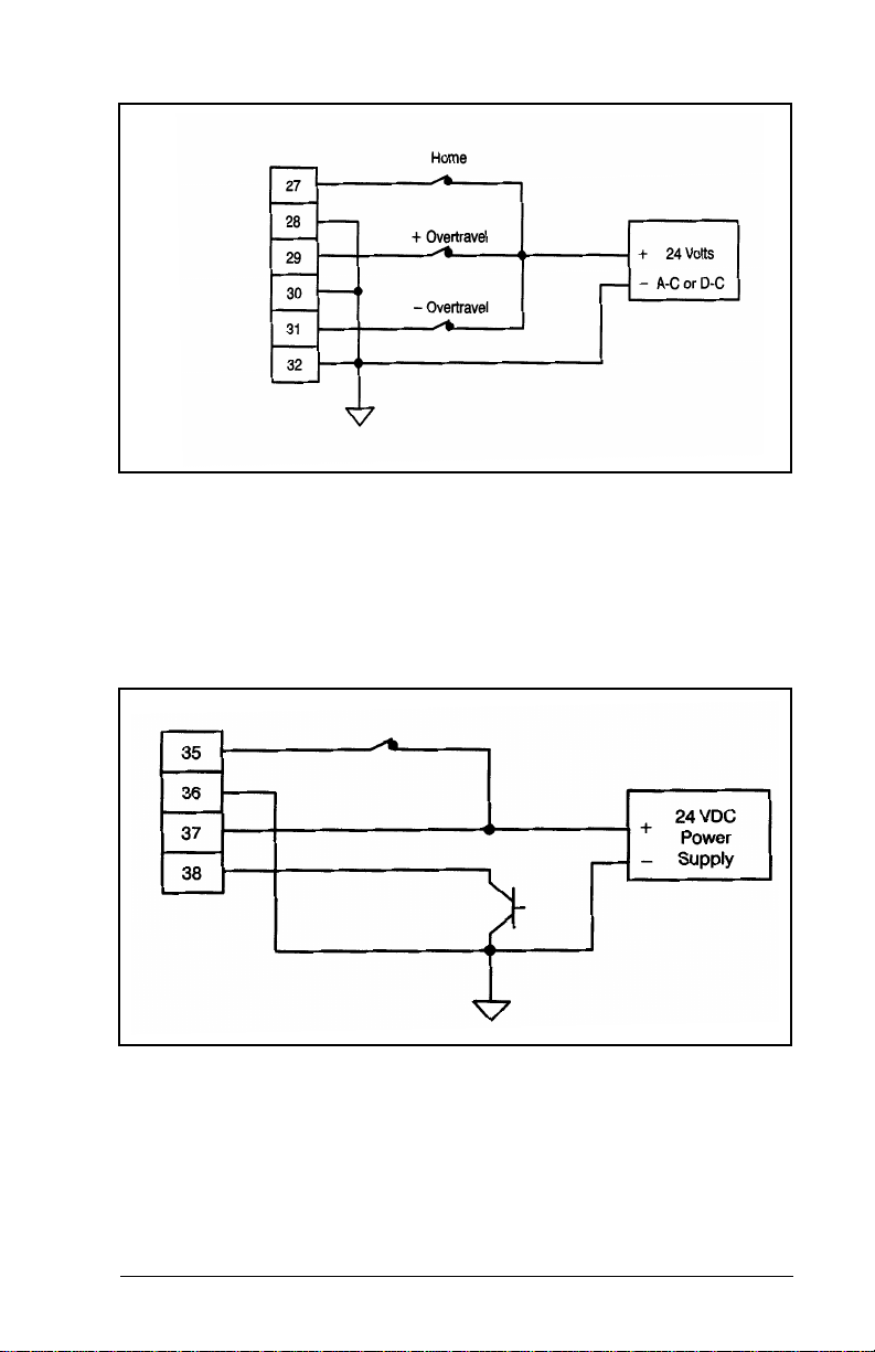
Figure 3.4 – Typical Limit Switch Connections
Step 8. Mount the registration sensors on your machine if
your application requires them. Fasten the field
wires from the sensors to the terminal strip. Use
extra care in routing these wires because these
signals are not filtered on the module. Typical field
connections are shown in figure 3.5.
Figure 3.5 – Typical Registration Input Connections
Step 9. Install the servo amplifier according to the
manufacturer’s instructions. Select the proper
mode of operation for the servo amplifier (current
or velocity). Select current mode for most
applications because all tuning can then be done
INSTALLATION
3-5
Page 22
in the software. If your application has unusually
high bandwidth requirements or your servo
amplifier functions as a velocity regulator only, use
the velocity mode.
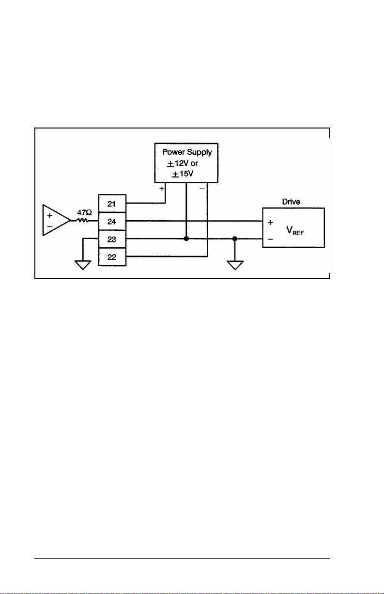
Step 10. Fasten the field wires from the drive reference and
power supply to the terminal strip. Typical field
connections are shown in figure 3.6 and 3.7.
Figure 3.6 – Typical Drive Reference/Voltage Reference
Connections with External P/S
Step 11. Connect the watchdog outputs on the terminal
strip into the drive enable circuit. This signal is
used to disable the servo if a problem develops in
the module. It must be installed in combination
with a hardwired E-stop circuit as well as a pair of
contacts that are controlled from a digital output
from DCS or AutoMax software. Typical field
connections are shown in figure 3.7.
3-6
2-Axis Servo Module M/N 57C422B
Page 23
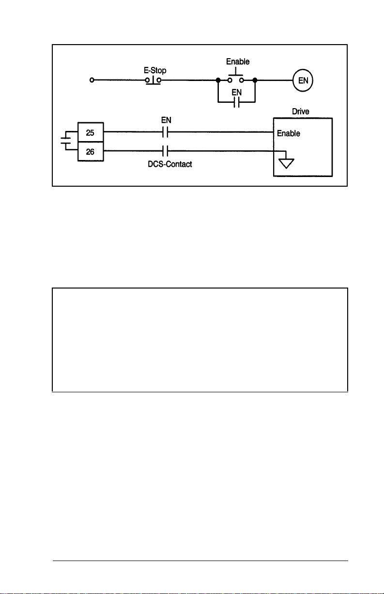
Figure 3.7 – Typical E-stop Circuit with Watchdog Output
The hardwired E-STOP ensures that you can
disconnect the drive under all conditions. The
contacts controlled by a DCS or AutoMax digital
output allow you to disable the drive in the event
of a processor failure or when faults are detected
by the application software.
WARNING
RELIANCE STRONGLY RECOMMENDS THE USE OF AN
EXTERNAL, HARDWIRED EMERGENCY STOP CIRCUIT THAT
WILL DISABLE THE SYSTEM IN CASE OF IMPROPER
OPERATION. UNCONTROLLED MACHINE OPERATION MAY
RESULT IF THIS PROCEDURE IS NOT FOLLOWED. FAILURE
TO OBSERVE THIS PRECAUTION COULD RESULT IN BODILY
INJURY OR DAMAGE TO EQUIPMENT.
Step 12. Fasten the field wires from the drive fault inputs to
the terminal strip. This signal is used to notify the
module that a problem has developed in the
servo. It must be connected if available. Typical
field connections are shown in figure 3.8. Be sure
to use the proper connections for your servo
amplifier.
INSTALLATION
3-7
Page 24
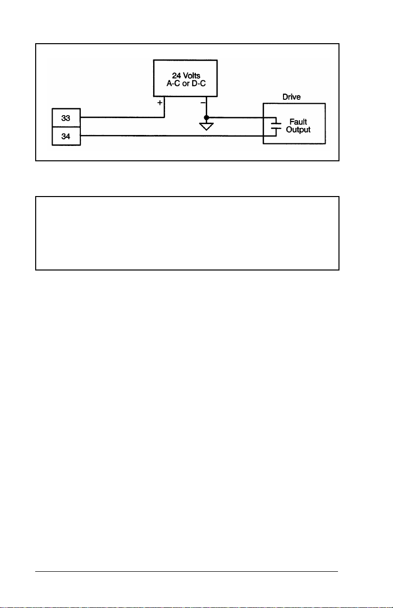
Figure 3.8 – Typical Drive Fault Connections
DANGER
ADJUSTMENTS ARE MADE WITH THE POWER ON.
EXERCISE EXTREME CAUTION AS HAZARDOUS VOLTAGE
EXISTS. FAILURE TO OBSERVE THIS PRECAUTION COULD
RESULT IN SEVERE BODILY INJURY OR LOSS OF LIFE.
Step 13. Verify power supply connections by performing
the following operations:
a. Make certain that all connectors from the
module and the encoders are disconnected.
b. Turn on power to the system.
c. Verify that you can read 5 volts on the proper
terminal strip and encoder connectors
(terminals 1 and 2).
d. Verify that you can read ±12 volts or ±15 volts
on the proper terminal strip connectors
(terminals 21, 22, 23).
e. Turn off power and reattach the connectors to
the module.
Step 14. Verify power supply connections at the encoder by
performing the following operations:
a. Make certain that all connectors at the
encoders are disconnected.
b. Turn on power to the system.
3-8
2-Axis Servo Module M/N 57C422B
Page 25

c. Verify that you can read 5 volts on the proper
pins of the encoder connector (at the encoder).
d. Turn off power and attach the connectors to
the encoders.
Step 15. Verify wiring connections by performing the
following operations:
a. Turn on power to the system.
b. Toggle all of the following digital inputs that you
are using in your application: the home L/S,
positive overtravel L/S, negative overtravel
L/S, drive fault, feedback registration, and
gearing registration. The appropriate LED on
the faceplate of the module should change
state as the input is toggled. Because the
signal may be very brief, it may be necessary
to use an oscilloscope to verity that it is
present.
Step 16. Verify the installation by connecting the
programming terminal to the system and running
the Programming Executive Software. Note that if
you are using a version 3.0 Programming
Executive and working with the sample application
program disk shipped with the Programming
Executive software, you will need to do a rack
import operation for the files in the 57C422
subdirectory first. See J-3684 for more information
and disregard steps a and b below.
INSTALLATION
a. Load the application disk that came with your
ReSource software.
b. Compile the BASIC tasks SETUPCNF.CNF
AXISSETUP.BAS, AXISSUB.BAS, and
AXISINIT.BAS.
c. Load the configuration and BASIC tasks onto
the CPU.
d. Use the RUN ALL command to start all four
tasks.
3-9
Page 26

e. Move the cable from the programming port on
the processor to the port labeled "LOCAL
COMM".
f. Select the menu option labeled
"COMMUNICATIONS INTERFACE".
g. Type C <CR> <CR>.
h. The screen on the programming terminal
should now display the test and setup menu for
the module. You should progress sequentially
through the menu from item 1 through item 8
before attempting to use the module.
Note that when you have finished configuring and tuning
your drives, you may save all of the data to a DOS disk file.
By adding this file to AXISINIT.BAS, you can eliminate the
need to re-configure your drive each time you use the test
and setup software.
3-10
2-Axis Servo Module M/N 57C422B
Page 27

3.3 Module Replacement
WARNING
THE MACHINERY BUILDER AND/OR USER ARE
RESPONSIBLE FOR INSURING THAT ALL DRIVE TRAIN
MECHANISMS, THE DRIVEN MACHINE, AND PROCESS
MATERIAL ARE CAPABLE OF SAFE OPERATION AT THE
MAXIMUM SPEED AT WHICH THE MACHINE WILL OPERATE.
FAILURE TO OBSERVE THESE PRECAUTIONS COULD
RESULT IN BODILY INJURY.
Use the following procedure to replace a module:
Step 1. Turn off power to the rack and all connections.
Step 2. Remove the connectors from the module.
Step 3. Loosen the screws that hold the module in the
rack. Remove the module from the slot in the rack.
Step 4. Place the module in the anti-static bag IT came in,
being careful not to touch the connectors on the
back of the module. Place the module in the
cardboard shipping container.
Step 5. Take the new module out of its anti-static bag,
Step 6. Insert the module into the desired slot in the rack.
Step 7. Attach the field terminal connectors (M/N 57C377)
Step 8. Turn on power to the rack.
INSTALLATION
being careful not to touch the connectors on the
back of the module.
Use a screwdriver to secure the module into the
slot.
to the mating halves on the module. Make certain
that the connectors are the proper ones for the
module and for the specific axes.
3-11
Page 28

3-12
2-Axis Servo Module M/N 57C422B
Page 29

CHAPTER 4
PROGRAMMING
This section describes how the data is organized in the
module and provides examples of how the module is
accessed by the application software. For more detailed
information on programming, refer to J-3675, J-3676, and
J-3677.
The module contains a total of 4096 16-bit registers, one set
of 2047 registers for each servo axis. The X axis uses
registers 0-2046. The Y axis uses registers 2048-4094.
Note that there are 2 exceptions to this basic register
organization scheme: registers 64 and 4095 (interrupt
control) are used for both axes. In other words, the use
of an interrupt on either axis will require you to perform
some function In these two registers. See section 4.49
for more information on interrupts.
The following register reference conventions are used
throughout this instruction manual. All register descriptions in
the following sections are based on the X axis and are
organized in numerical order, except for interrupt and cam
registers, which are described in sections 4.49 and 4.50. The
equivalent Y axis registers are given in parentheses in the
figure that accompanies each register description. Appendix
E is a numerical register summary with page number
references.
Register numbers listed together separated by a comma
(e.g., 11, 12) signify a double precision (32-bit) value.
Register numbers listed together separated by a slash (e.g.,
104/105) indicate that both registers have a similar function
and should be considered together. This notation does not
indicate a double precision value.
For ease of locating descriptions for individual bits within
registers, bit names are underlined in the sections where the
bits are described. Bit names are placed between quotation
marks when they are only referred to. In some cases,
PROGRAMMING
4-1
Page 30

registers with individual bit descriptions are shown with the
bits broken up into groups of four for ease of interpretation in
monitoring the registers in hexadecimal format.
At times register and bit references will be in the form of
"RA,bB," where "A” is the register number and "B" is the bit
number.
4.1 Configuration
Before an application program can be written, it is necessary
to configure the definitions of variables that must be
accessible to all tasks in the rack. This section describes how
to configure the module.
If you are using V3.0 or later of the Programming Executive
software, you can configure the module using a special
software "form" that allows you to fill in the names of the
registers and bits. See the Programming Executive
instruction manual for more information on configuration
forms.
If you are using an earlier version of the programming
executive, you will need to create a configuration task to
configure the registers/bits on the module. See Appendix H,
for more information on creating a configuration task.
4-2
2-Axis Servo Module M/N 57C422B
Page 31

4.2 Register 0: Encoder Setup
Register 0 is used to configure the gearing reference and
feedback encoder inputs for the axis. Refer to figure 4.1.
Figure 4.1 – Encoder Configuration Register
The feedback encoder mode
channels from the encoder will be interpreted by the module.
If the step/direction mode is selected, a high to low transition
of Channel A causes a count. If Channel B was low, the
count is incremented. If Channel B was high, the count is
decremented.
If the step +
Channel A results in the count being incremented. A high to
low transition of Channel B results in the count being
decremented.
If the *1 quardrature is selected, only one edge of channel A
is counted. (Note that *1 quadrature is available only on B/M
57422-2C and later versions of the module.) If the *2
quadrature mode is selected, both the rising and trailing
edges of Channel A are counted. The direction is determined
from the state of Channel B.
PROGRAMMING
bits specify how the A and B
mode is selected, a high to low transition of
4-3
Page 32

If the *4 quadrature mode is selected, both edges of
Channels A and B result in counts. The direction is
determined by the channel changing state and the state of
the opposite channel. All subsequent references to counts
include the quadrature calculation.
Note: Any references to counts within this instruction
manual take into account the quadrature multiplier
selected in this register.
You can use the feedback encoder polarity
rotation of the encoder as seen by the application software.
This is analogous to swapping the encoder leads to alter the
electrical direction of rotation.
Specifying the axis as "rotary" using the feedback linear/
rotary bit causes the module to subtract or add one
revolution of counts from the command position and the
actual position whenever the encoder crosses the revolution
boundary. This allows infinite range for rotary axis. If the axis
is specified as linear, the feedback will simply increment or
decrement as the axis is moved forward or in reverse.
4.3 Register 1: Drive Setup
Register 1 is used to configure the servo drive. Refer to
figure 4. 2.
bit to change the
Figure 4.2 – Control Loop Configuration Register
The analog output
from the module should be configured to
work with the control loop on the drive (either current or
velocity).
4-4
2-Axis Servo Module M/N 57C422B
Page 33
The output polarity bit is used to alter the sign of the drive
reference for a given error. This is analogous to swapping
the wires for the drive reference.
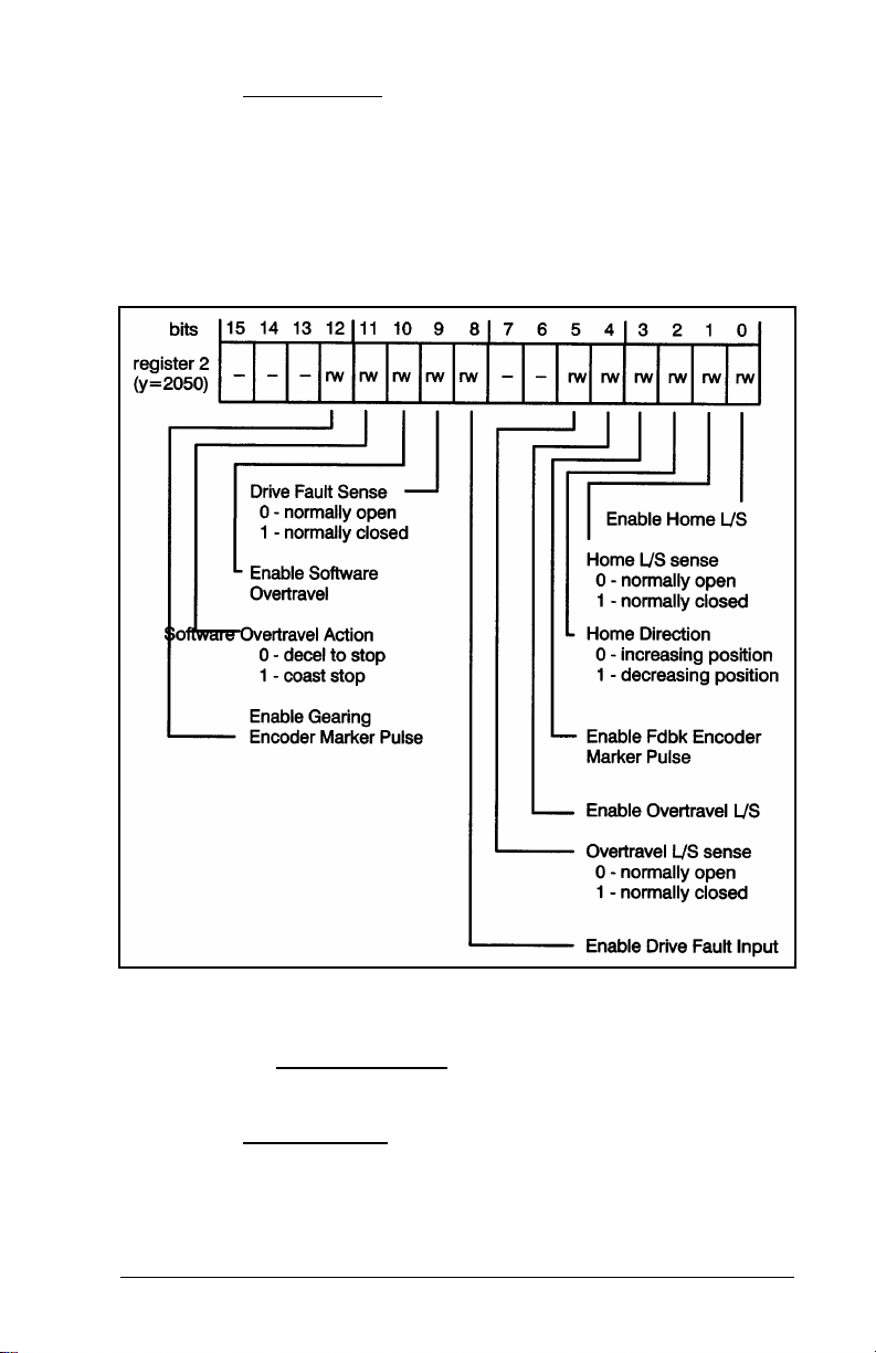
4.4 Register 2: Switch Setup
Register 2 is used to configure the home and overtravel limit
switches. Refer to figure 4.3.
Figure 4.3 – Home and Overtravel Configuration Register
If you have a home limit switch on your machine, you should
use the enable home L/S.
of the limit switch as either normally open or normally closed.
The home direction
drive will move during the initial phase of the homing
sequence.
PROGRAMMING
Y ou can define the asserted sense
bit is used to define the direction that the
4-5
Page 34

If you intend to use the feedback marker during the home
sequence, you should enable the feedback encoder marker
. Refer to section 4.35 for more information on the
pulse
“home axis” command in register 66.
To prevent your machine from moving beyond specified
physical limits, use the enable overtravel L/S
bit. You can
define the condition to be true when the limit switch is closed
(normally open) or open (normally closed). If an overtravel
limit switch is tripped during operation, the control will be
turned off and, if programmed, the drive will coast to a stop.
The machine will then have to be moved off the overtravel
limit switch before the control can be re-enabled. In critical
applications, hardwire the overtravel L/S into the emergency
stop circuit so that the drive will be disabled regardless of the
state of the control.
The drive fault input
is a simple means of shutting off the axis
control. This input can be either a fault signal from the drive
or an E-STOP push-button. You can define the asserted
sense of the input as either normally open or normally
closed. If the drive fault input is tripped, the axis control will
be disabled and, if programmed, the drive will coast to a
stop.
WARNING
RELIANCE STRONGLY RECOMMENDS THE USE OF AN
EXTERNAL, HARDWIRED EMERGENCY STOP CIRCUIT THAT
WILL DISABLE THE SYSTEM IN CASE OF IMPROPER
OPERATION. UNCONTROLLED MACHINE OPERATION MAY
RESULT IF THIS PROCEDURE IS NOT FOLLOWED. FAILURE
TO OBSERVE THIS PRECAUTION COULD RESULT IN BODILY
INJURY.
The software overtravel
bit is a programmable way of limiting
machine travel. You can define the action that occurs when
the software overtravel limit is exceeded as either a decel to
stop or a coast to stop. If you have specified a decel to stop,
the drive will decelerate at the specified rate to zero speed
and regulate about that position. If you have specified a
coast stop, the drive control will be disabled and the drive will
coast to rest. When the drive has exceeded a software
overtravel limit, and if you have specified a "decel to stop,"
the drive can be commanded to move away from the
overtravel conditio n.
4-6
2-Axis Servo Module M/N 57C422B
Page 35

You should enable the gearing marker pulse if you intend to
use it to initialize the home position of the gearing encoder.
Refer to section 4.35 for the "set gearing position" command
in register 66 for more information .
4.5 Register 3: Propo rtional Gain
Register 3 contains the proportional gain for the module. This
value is read by the module whenever the “change default
setups” command in register 66 is issued. See Section 5.2
for more information on turning.
Figure 4.4 – Proportional Gain Register
4.6 Register 4: Integral Gain
Register 4 contains the integral gain for the module. This
value is read by the module whenever the "change default
setups" command in register 66 is issued. See Section 5.2
for more information on tuning.
Figure 4.5 – Integral Gain Register
4.7 Register 5: Velocity Gain
Register 5 contains the velocity gain for the module. This
value is read by the module whenever the "change default
setups" command in register 66 is issued. See Section 5.2
for more information on tuning.
PROGRAMMING
4-7
Page 36

Figure 4.6 – Velocity Gain Register
4.8 Register 6: Feedforward Gain
Register 6 contains the feedforward gain for the module. This
value is read by the module whenever the “change default
setups” command in register 66 is issued. See section 5.2 for
more information on tuning.
Figure 4.7 – Feedforward Gain Register
4.9 Register 7: Deadband Compensation
Register 7 contains the deadband compensation for the
module. This value is read by the module whenever the
"change default setups" command in register 66 is issued.
See Section 5.2 for more information on tuning.
Figure 4.8 – Deadband Compensation Register
4-8
2-Axis Servo Module M/N 57C422B
Page 37
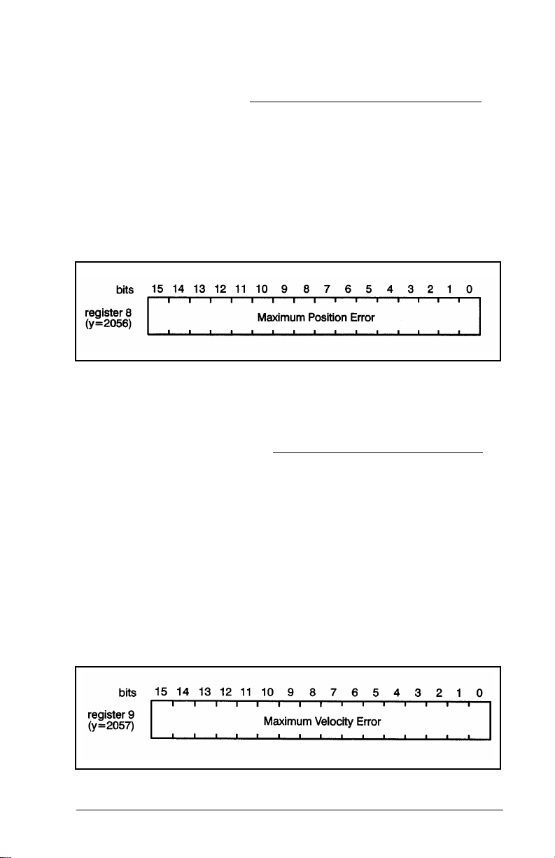
4.10 Register 8: Maximum Position Error
Register 8 contains the maximum allowable position error
that is used to determine faults. Position error is defined as
the difference between commanded and actual position. The
value depends on the system configuration and performance
required. If this limit is exceeded, the feedback will be
disabled and the appropriate fault bits will be set in the fault
register (R73). Note that register 8 will be examined by the
module even when it is in velocity mode. The module may
respond to excessive position error while running in velocity
mode.
Figure 4.9 – Maximum Position Error
4.11 Register 9: Maximum Velocity Error
Register 9 contains the maximum allowable velocity error.
Velocity error is the difference between the commanded and
the actual velocity. Excessive velocity error usually indicates
excessive acceleration, excessive deceleration, or a
disconnected encoder. The maximum velocity error is
determined using the following equation.
Maximum
Velocity Error=(max acceptable ve locity error in eng.
The result of the equation is in counts/scan. If this limit is
exceeded, the feedback will be disabled and the appropriate
fault bits will be set in the fault register (R73).
PROGRAMMING
units/sec*encoder cou nt s/ en g uni t s) (.00125)
Figure 4.10 – Maximum Velocity Error Register
4-9
Page 38

4.12 Register 10: In-Position Tolerance
Register 10 defines the tolerance within which the axis is
considered to be in-position. This value is read by the
module whenever the "enable feedback" (register 65) or
"change default setups" (register 66) command is issued.
The axis is considered to be in-position if the absolute value
of the difference between where the axis should be and
where it actually is, is less than this tolerance. This condition
is available as "axis locked" status in register 72. The
in-position tolerance is in units of encoder counts. Refer to
figure 4.11.
Figure 4.11 – In-Position Tolerance Register
4.13 Registers 11, 12: Positive Overtravel Limit
Registers 11, 12 define the positive overtravel limit. This
value is read by the module whenever the “enable feedback”
(register 65) or “change default setups” (register 66)
command is issued. This limit applies only if the axis is in the
linear mode (register 0, bit 4=0) and “software ove rtrav el ”
was enabled in register 2. The negative overtravel limit must
be algebraically less than the positive overtravel limit or a
motion fault will occur. The software overtravel limits are in
units of encoder counts.
Registers 11 -12 are also used to provide a maximum travel
for the "tune dynamics" (register 66) or "tune
limit
4-10
2-Axis Servo Module M/N 57C422B
Page 39

feedforward" (register 66) commands.
Figure 4.12 –
Positive Overtravel Limit Registers
4.14 Registers 13,14: Negative Overtravel Limit
Registers 13,14 define the negative overtravel limit. This
value is read by the module whenever the "enable feedback"
(R65) or change default setups" (R66) command is issued.
This limit applies only if the axis is in the linear mode.
(RO,b4=0) and "software overtravel" in R2 has been
enabled. The negative overtravel limit must be algebraically
less than the positive overtravel limit (R11, 12) or a motion
fault will occur. The negative overtravel limit is in units of
encoder counts.
Figure 4.13 –
Negative Overtravel Limit Registers
4.15 Registers 15,16: Low Speed Homing
Reference
Registers 15, 16 contain the low speed reference used
during the homing sequence. This value is read by the
module whenever the "home axis" (register 66) command is
issued. The low speed reference is used by the module
whenever it is attempting to locate the feedback marker
pulse. Refer to figure 4.14. The reference units are:
PROGRAMMING
4-11
Page 40

(encoder counts/sec) * 65.536
Figure 4.14 –
Low Speed Homing Reference Register
4.16 Registers 17,18: Command Position
Registers 17, 18 contain numeric parameters used in
various commands. All of the commands do not require the
use of all of the parameters in registers 17-24. Refer to figure
4.15.
Figure 4.15 – Command Position Registers
Registers 17,18 contain the command position.
read by the module whenever any of the following
commands are issued in register 66: "index/move," "define
fdbk position," "home axis," "tune gains," "define gearing
position," "set gearing position when marker occurs" and
"define sync position." The units are encoder counts.
This value is
The value is also read when any of the following commands
are issued in register 67: "enable passive homing on
feedback encoder marker pulse," "enable passive homing on
gearing encoder marker pulse,". "enable relative change in
feedback position," and "enable relative change in gearing
position."
4-12
2-Axis Servo Module M/N 57C422B
Page 41
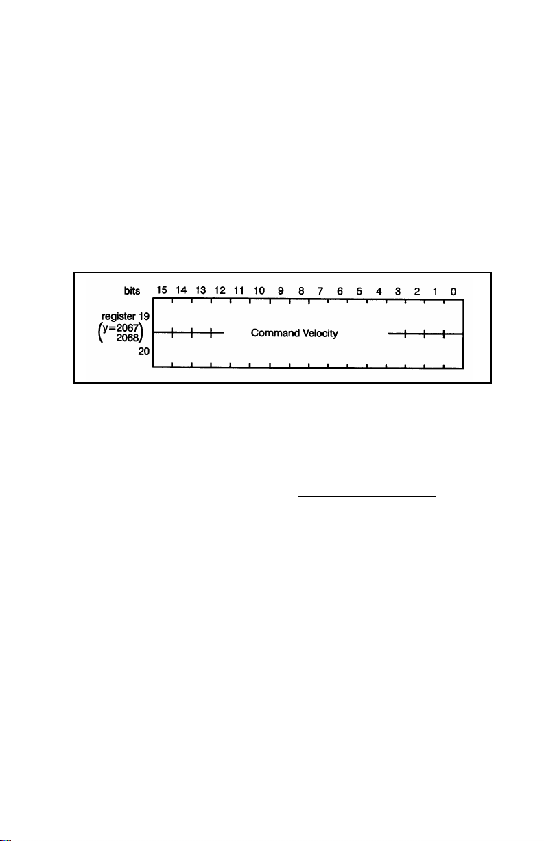
4.17 Registers 19, 20: Command Velocity
Registers 19, 20 contain the command velocity. This value is
read by the module whenever the following commands are
issued: "index/move", "home axis", "tune dynamics", "tune
feedforward", or "change velocity" in R66; or "velocity
control" in R65. The command velocity units are:
(encoder counts/sec)*65.536
The maximum speed that can be programmed is 65,536,000
counts/sec.
Figure 4.16 – Command Velocity Registers
4.18 Registers 21, 22: Command Acceleration
Registers 21, 22 contain the command acceleration. This
value is read by the module whenever the following
commands are issued: “index/move", "home axis", "tune
dynamics", or "tune feedforward" in R66; or "velocity control"
in R65. The command acceleration is calculated as follows:
acceleration = (eng units/sec/sec)*(en coder counts/eng units) *.0 6 5 5 3 6
The maximum programmed value is 3.28 x 10¹⁰ encoder
counts/sec/sec. The acceleration rate and deceleration rate
(R23, 24) do not need to be equal. However, the deceleration
rate must not be less than one-fifth the acceleration rate.
PROGRAMMING
4-13
Page 42
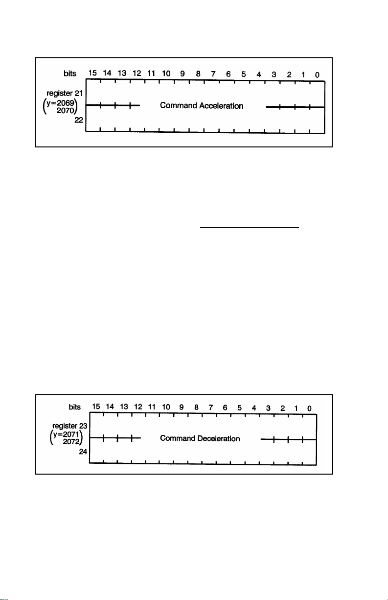
Figure 4.17 – Command Acceleration Registers
4.19 Registers 23, 24: Command Deceleration
Registers 23, 24 contains the command deceleration. This
value is read by the module whenever the following
commands are issued: "index/move", "home axis", "tune
dynamics", or "tune feedforward" in R66; or "velocity control"
in R65. The command deceleration is calculated using the
same formula used for calculating "command acceleration"
in R21, 22. In addition, the same maximum value applies to
both command acceleration and deceleration. See section
4.18 for more information.
Note that the ratio between the deceleration rate and the
acceleration rate must be between .2 to 1 and 5 to 1. The
"stop motion" command in register 66 will use the value in
23, 24, depending on the state of the "stop action" bit in
register 65. See sections 4.34 and 4.35 for more information.
Figure 4.18 – Command Deceleration Registers
4-14
2-Axis Servo Module M/N 57C422B
Page 43

4.20 Registers 25, 26: Gear Ratio
Registers 25,26 contain the gear ratio between the feedback
and gearing reference axes. This value is read by the module
whenever the "enable gearing" (register 65) or "change gear
ratio" (register 67) command is issued. Refer to figure 4.19.
The gear ratio calculation method depends on the value of
"gear ratio format" (R38, b2). If this bit is equal to 0, the value
can be calculated with the following equation:
Gear Ratio = (feedback axis travel) * 16777216
gearing reference axis travel)
If R38, b2 is set, the gear ratio is the ratio of two 16-bit
numbers in registers 25 and 26. Register 25 is the
numerator. Register 26 is the denominator. The denominator
cannot be a negative number or 0.
If the result of the calculation is a repeating fraction, e.g., 1/3,
the module will keep track of all remainders for internal
gearing calculations. The allowable ratio range is 127:1 to
1:32767.
Note that if the gearing bit mode is set (R65, b1) and any
illegal condition is present in registers 25,26, gearing is not
enabled. If gearing is already enabled and a "change gear
ratio" command is issued (R67, b3), with illegal parameters
in registers 25,26, an illegal command fault will result.
Figure 4.19 – Gear Ratio Registers
4.21 Register 27: User LEDs
Register 27 is used to drive the three user controlled LEDs
on the faceplate of the module. These bits are read by the
module only when the "update LEDs" (register 66) command
is issued. Register 2075 (Y axis) can be used to update the
PROGRAMMING
4-15
Page 44

same user LEDs when the “update LEDs" co mma nd
(register 2114) is issued. Since this could lead to confusion,
you should only use one register (either 27 or 2075) in an
application, but not both. Refer to figure 4.20.
Figure 4.20 – User-Controlled LED Register
4.22 Register 28: Direct Drive Reference
Command
Register 28 can be used to provide a direct reference to the
drive. This value is read contin uou sl y by the mod ule
whenever the "output volts" (register 65) command is issued.
The values may range from -1984 to 1984 corresponding to
an output range of +
10 volts. Refer to figure 4.21.
Figure 4.21 – Drive Command Reference Register
4.23 Registers 29, 30: Sync Position
Registers 29, 30 contain the sync position. The sync position
register can be used to define a position where an action
needs to occur. This register is read by the module whenever
the "define sync position" (register 66) command is issued.
The sync position is used in conjunction with "position >=" or
"position <" bits in register 72. When the value in the sync
4-16
2-Axis Servo Module M/N 57C422B
Page 45
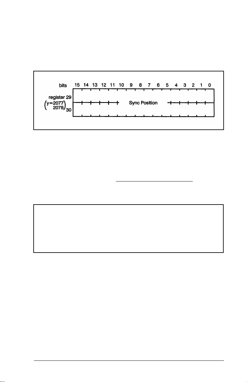
position registers is changed, the "position >=" and "position
<" bits in register 72 are undefined until another "define sync
position" command is issu ed. The sy nc position will be
compared to the actual current feedback position, an internal
value (not registers 74/75). The units are encoder counts.
Refer to figure 4.22.
Figure 4.22 – Sync Position Registers
4.24 Register 31: Maximum Voltage Reference
Register 31 limits the maximum voltage reference to the
drive. This value should be set prior to outputting any
reference to the drive.
CAUTION
ALWAYS PLACE A LIMIT ON THE MAXIMUM VOLTAGE
REFERENCE TO THE DRIVE. FAILURE TO OBSERVE THIS
PRECAUTION COULD RESULT IN DAMAGE TO OR
DESTRUCTION OF THE EOUIPMENT.
The value in register 31 is read by the module whenever the
"change default setups" command in register 66 is issued.
The value may range from 0 to 1984, corresponding to an
output range of 0 to 10 volts. Refer to figure 4.23.
PROGRAMMING
4-17
Page 46
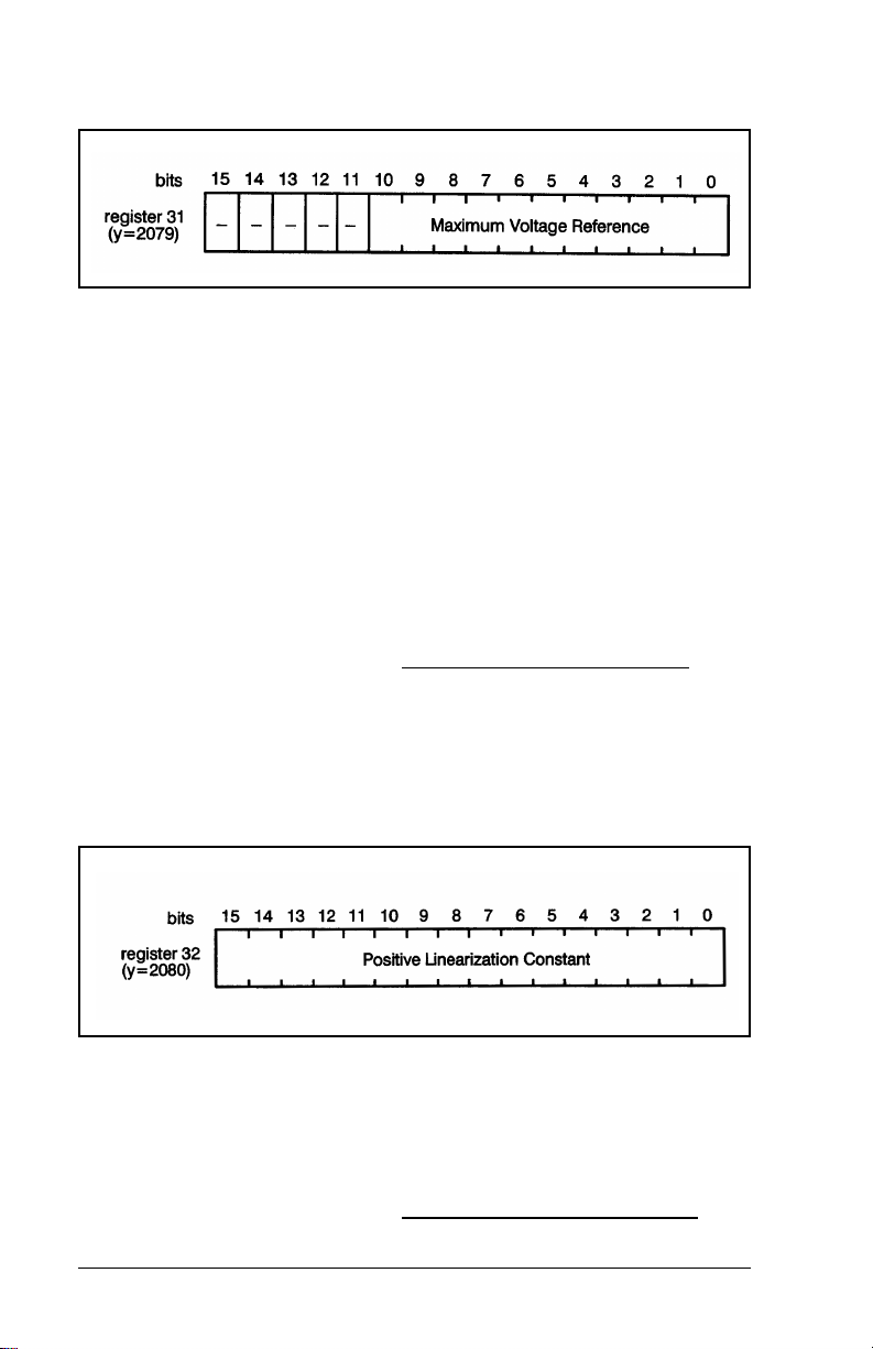
Figure 4.23 – Maximum Voltage Reference Output Register
When the drive is configured as a velocity regulator, register
31 should be used to limit the voltage reference. This feature
is used if the drive requires less than 10 volts for full speed. If
the drive is configured as a current regulator, register 31 can
be used as a programmable current clamp. The "output
clamped" bit in register 73 will be set when the voltage
reference is limited by the value in register 31.
4.25 Register 32: Positive Lineari zation Constant
Register 32 contains the positive linearization constant for
the velocity output. This value is used by the module to
insure that the velocity output is linearly related to the
number computed by the software. Initially, this value should
be set to -1. The "tune dynamics" command in auto-tuning
will adjust this number if the drive has been configured as a
velocity regulato r.
Figure 4.24 – Positive Linearization Constant Register
4.26 Register 33: Negative Lineari zation
Constant
Register 33 contains the negative linearization constant for
the velocity output. This value is used by the module to
4-18
2-Axis Servo Module M/N 57C422B
Page 47
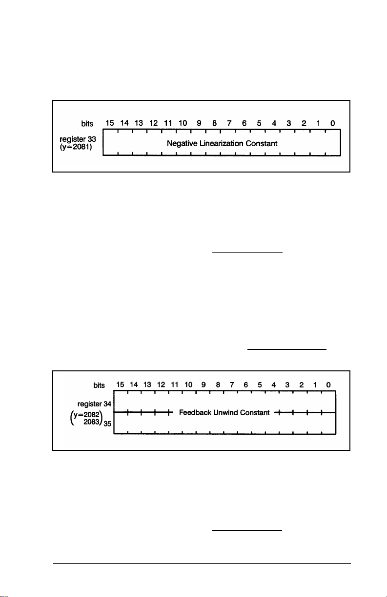
insure that the velocity output is linearly related to the
number computed by the software. Initially, this value should
be set to -1. The "tune dynamics" command in register 66 will
adjust this number if the drive has been configured as a
velocity regulato r.
Figure 4.25 – Positive Linearization Constant Register
4.27 Registers 34, 35: Feedback Unwind Constant
Registers 34, 35 contain the unwind constant for the
feedback encoder. Refer to figure 4.26. This parameter is
used in the rotary mode selected in register 0 (Encoder
Setup). This value is read by the module whenever the
"home axis" or "change default setup" commands (register
66) are issued. The unwind constant is equal to the number
of encoder counts per axis revolution. Use the following
equation to determine the unwind constant:
Unwind Constant = encoder counts/rev * encoder revolutions
axis revolution
Figure 4.26 – Feedback Unwind Constant Registers
4.28 Registers 36, 37: Gearing Unwind
Constant
Registers 36, 37 contain the unwind constant for the gearing
encoder. This parameter is used in the rotary mode selected
PROGRAMMING
4-19
Page 48
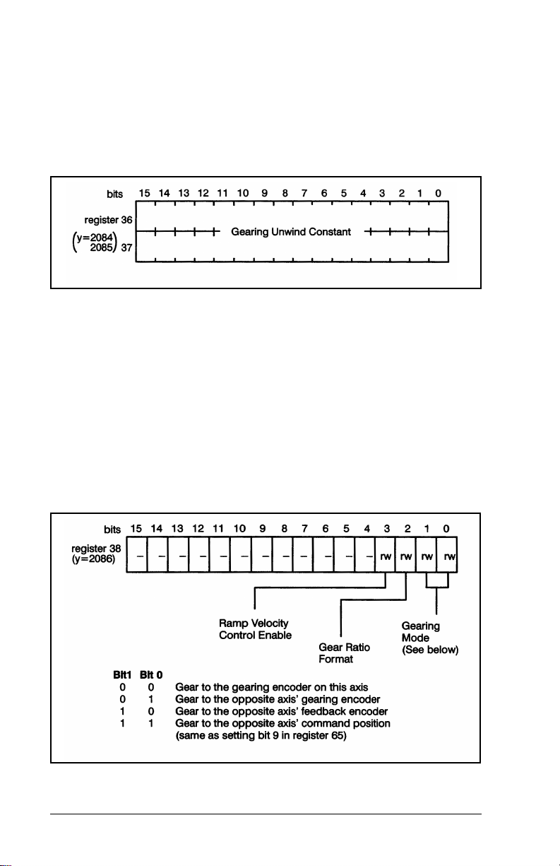
in register 0 (Encoder Setup). This value is read by the
module whenever the "home axis" or "change default setup"
commands in register 66 are issued. The unwind constant is
equal to the number of encoder counts per axis revolution.
Use the same formula in the gearing unwind constant and
the feedback unwind constant. See section 4.27 above for
the formula.
Figure 4.27 – Gearing Unwind Constant Registers
4.29 Register 38: Gearing Modes, Ratio Format, Ramp Velocity Control
Register 38 is used to determine gearing mode if bit 9 in
register 65 is not set (0), to select the gear ratio format, and
to enable ramp velocity control. Note that changes to
registers 38
register 65
will be ignored while gearing mode is enabled in
. See figure 4.28.
Figure 4.28 – Gearing Mode, Ratio Format, and Ramp Velocity Control Register
4-20
2-Axis Servo Module M/N 57C422B
Page 49

Note that the strobed gearing registration position (registers
86,87) and the current gearing position (registers 76, 77)
data are not affected by the selections made in register 38. X
and Y axis gearing registration and current gearing position
values will always be strobed from their respective hardware
encoder channels.
Bit 2 in register 38 selects the format of the gear ratio.
default (0) is a 32-bit number stored in registers 25,26 scaled
by 16777216. Setting bit 2 to 1 allows you to express the
gear ratio as a ratio of two 16-bit numbers in registers 25 and
26. See section 4.20 for more information.
Bit 3 in register 38 enables ramp velocity control
follower axis when the master axis is moving and gearing is
enabled, when you are changing from the non-geared to the
geared mode, or when the gear ratio is changed while
gearing is enabled. This command will limit the rate of
acceleration and deceleration until the axis is synchronized
with the master. Note that this limit applies only to trapezoidal
acceleration, not to S-curve acceleration. Once the axis is
synchronized with the master, there is no limit on
acceleration/deceleration through register 38, bit 3. When
ramped velocity control is selected, if gearing is disabled
while the follower axis is still moving, the follower axis will
continue to move at that velocity until a stop motion
command is issued in register 66, bit 6.
4.30 Registers 39, 40: Backlash Compensation
Registers 39 and 40 are used to store a signal value (in
counts) that selects the amount of backlash compensation.
The sign of the value corresponds to the approach direction.
Refer to figure 4.29.
The
on the
For example, a value of +20 entered here will mean that an
incremental move of 100 counts will result in an actual move
of 100 counts and then a stop. The same move in the
negative direction will result in the axis moving - 120 counts,
+20 counts, and then a stop.
PROGRAMMING
4-21
Page 50
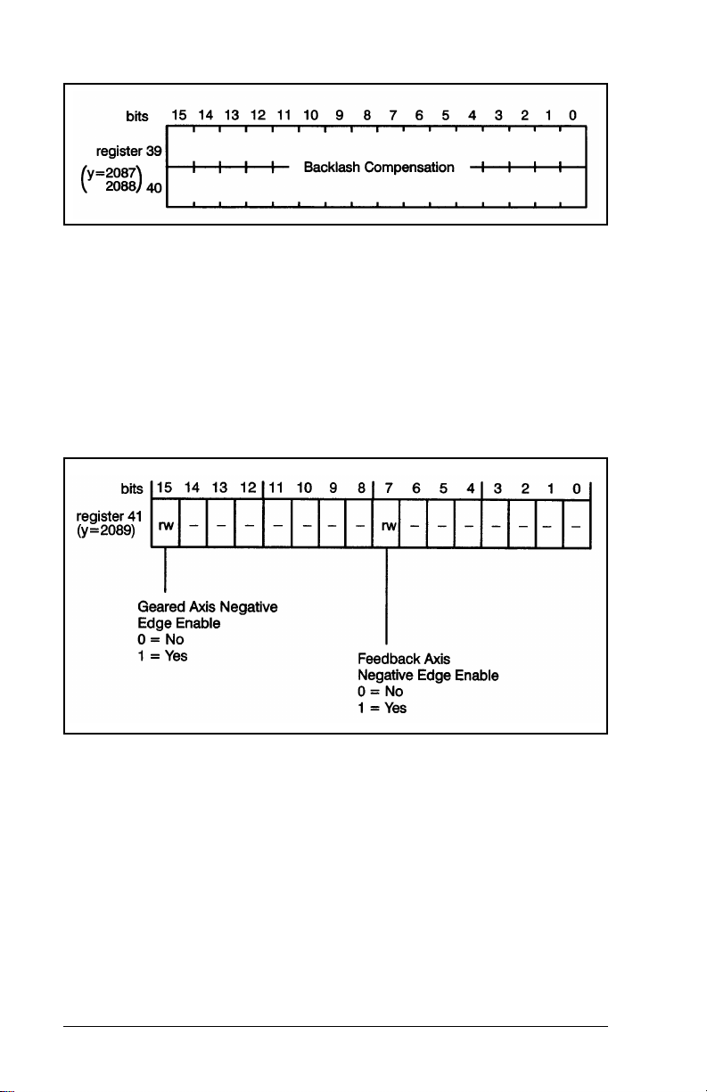
Figure 4.29 – Backlash Compensation Registers
4.31 Register 41: Registration Inp ut Edge Detection
Register 41 selects which edge (rising and falling, or falling
only) of the gearing or feedback registration input will be
recognized by the module. This register is available only on
the B/M 57422-2 module.
Figure 4.30 – Registration Edge Detection Register
When bits 7 and 15 are left at the default value (0), the
module will recognize both the rising and failing edges of
registration inputs.
4.32 Register 63: Auto-Acknowledge
Register 63 is the command auto-acknowledge register.
When bit 0 is set to 1, the module will automatically clear the
command registers (66 and 67) instead of requiring an
application task to clear the command registers. The user
4-22
2-Axis Servo Module M/N 57C422B
Page 51

need only wait for the value in registers 66 and 67 to be zero
before issuing the next command.
Figure 4.31 – Auto-Acknowledge Register
4.33 Register 64: I nterrupt Reset
To reset the interrupt, the application task must write a zero
value to register 64. Note that register 64 Is used as the
Interrupt reset register for both the X-axis and the
Y-axis. See figure 4.32.
Figure 4.32 – Interrupt Reset Register
4.34 Register 65: Mode
Register 65 is a control register used to command operating
modes on the module. This register is read by the module
continuously. Refer to figure 4.33.
PROGRAMMING
4-23
Page 52
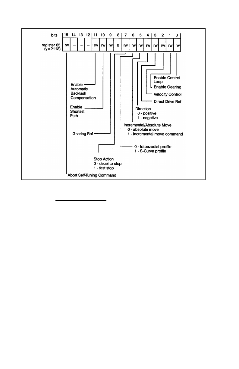
Figure 4.33 – Mode Register
The enable control loop
bit commands the module to switch
on the control loop (position/velocity) and enable the drive
reference from the module. It also causes the
microprocessor to read set-up data and reset faults when
toggled.
The enable gearing
bit commands the module to ratio the
feedback encoder to the gearing encoder. This function is
useful for electronic lineshaft applications. Note that if the
gearing function is used, register 25, 26 must contain the
gear ratio .
If gearing is enabled or disabled with ramp velocity control
disabled, the axis will accelerate or decelerate in current
limit.
If gearing is disabled with ramp velocity control enabled, it is
possible to do an absolute move while the drive is still in
motion. The new commanded position to which to move
must be either behind the current position, or farther forward
than the current position plus the distance required to
4-24
2-Axis Servo Module M/N 57C422B
Page 53

decelerate to a stop. If the position is not beyond the
distance required to decelerate, the axis will overshoot.
The velocity control
bit causes the axis to run at the velocity
defined by the command velocity input (registers 19, 20).
This mode is used to run the axis as a velocity regulator.
Velocity regulation is achieved by sending a constantly
variable position reference to the position loop. This means
the axis can still "trip" due to position error, i.e., the value in
register 80 is greater than the value in register 8.
The direct drive reference
bit commands the module to
output the value in register 28 to the drive. This command
causes the axis to function like a D/A converter.
The direction
bit specifies the relationship between the
gearing axis and feedback axis when gearing is used, or to
specify the sign of the velocity command when velocity
control is used. When gearing is active, a positive direction
indicates that the gearing and feedback axis will move in the
same direction. A negative direction indicates that they will
move in opposite directions. If you jog into the positive or
negative software travel limit, and then try to jog off the limit
by changing the state of the direction bit, the axis will remain
at the travel limit. To be able to jog off a software travel limit,
you must first turn off the velocity control bit (bit 2), and then
turn it back on with the direction bit changed. See sections
4.13 and 4.14 for more information on software overtravel
limits.
The incremental/absolute move
move to be made. If you specify an absolute move, the axis
will move to the position specified in register 17. If an
incremental move is specified, the module will add the
current value in register 17 to the position of the axis to
determine the next position.
The velocity profile
will execute when accelerating or decelerating, whether
doing an absolute move (bit 5) or velocity control (bit 2).
Using an S-Curve profile doubles the time required to
accelerate and decelerate compared with the trapezoidal
profile. Note that If you select S-Curve, you cannot change
velocity while moving (register 66 bit 8) or an illegal
command fault will be generated. See the figure below for a
sample profile comparison.
PROGRAMMING
bit specifies the type of
bit specifies the type of profile the drive
4-25
Page 54

The stop action bit defines the way that the drive will stop
when a "stop motion" command (register 66) is issued. If a
"decel to stop" is selected and the module is not in the cam
mode, the drive will ramp to a zero speed at the rate in
register 23, 24 when the motion is started. If the module was
in the time cam mode, it will complete the current cam cycle
and return to the beginning of the profile. If the module was in
position cam mode, cam execution will stop immediately. If a
"fast stop" is selected, the module will command the drive to
decelerate at the rate specified in register 23, 24 when the
"home" command is issued. If a "fast stop" is selected, a
"home", or "tune dynamics" command MUST be done to load
the "fast stop" deceleration rate. If the application does not
normally do a "home" command, you can use the mode of
homing that does not cause any motion. See section 4.35 for
more information. The feedback loop will remain enabled.
The gearing reference
bit defines the source of the gearing
reference. Bit 9 = 0 if you want the gearing reference to be
determined by register 38. If the reference is an encoder, you
4-26
2-Axis Servo Module M/N 57C422B
Page 55

must connect the encoder to the proper inputs on the
terminal strip. If you want to gear to the opposite axis
command position, set bit 9 = 1. This option does not require
you to make any external wiring connections. In this mode,
the geared axis will follow all changes to the command
position of the reference axis.
The enable shortest path
the shortest path to take when doing an absolute move in
rotary mode.
No Incremental moves can be performed if this bit is set.
If rotary mode is not selected (in register 0, bits 4 and 12),
setting the enable shortest path bit will cause an illegal
command fault.
The enable automatic backlash compensation
to enable automatic backlash compensation as specified in
registers 39 and 40.
The abort self-tuning
command. This is the only command that is accepted while
the module is doing a self-tune.
bit allows the module to determine
command is used to abort a self tuning
4.35 Register 66: Comman d
Register 66 is used to command actions from the module.
The bits in this register and in register 67 are mutually
exclusive, i.e., only one function may be selected at a time
from either register. This register is read by the module
continuously. Refer to figure 4.34.
bit allows you
PROGRAMMING
4-27
Page 56

Figure 4.34 – Command Register 66
The index/move command will cause the axis to move
according to the parameters defined in registers 17-24 and
register 65, bit 5. Once a move has been initiated, the accel
and decel rates may not be changed until the move is
complete. Velocity can be changed during a move by issuing
a "change velocity" command. Final position may be
changed during a move by issuing another index move.
The define feedback position
command will cause the
current position of the feedback to be defined by the value in
registers 17-18. The axis will not move.
The home axis
command will cause the axis to perform the
homing sequence that was defined by the bits in register 2.
Four different homing sequences for the feedback axis are
possible, depending on whether a home limit switch and
encoder marker pulse are specified in register 2. These four
sequences are described below. Note that it is also possible
to home on the feedback or gearing encoder marker pulse.
See section 4.36 for more information. When a "home"
command is issued, the deceleration rate in registers 23, 24
4-28
2-Axis Servo Module M/N 57C422B
Page 57

is saved and used for the "stop motion" command if the "stop
action" bit is set in register 65.
1. No home limit switch and no encoder marker pulse.
When the "home axis" command is issued, the value in
registers 17, 18 is assigned to the current axis position.
The axis does not move.
2. Encoder marker pulse only. When the "home axis"
command is issued, the axis moves in the specified
direction at the slow home speed (registers 15, 16) until
the marker pulse is detected. The value in registers 17,
18 is then assigned to the axis position.
3. Home limit switch only. When the "home axis" command
is issued, the axis moves in the specified direction at the
fast home speed (registers 19, 20) until the home limit
switch is detected. The axis then stops and moves in the
opposite direction at the slow home speed (registers 15,
16) until the limit switch is cleared. The value in registers
17, 18 is then assigned to the axis position.
4. Both the home limit switch and encoder marker pulse.
When the "home axis" command is issued, the axis
moves in the specified direction at the fast home speed
(registers 19, 20) until the home limit switch is detected.
The axis then stops and moves in the opposite direction
at the slow home speed (registers 15, 16) until the limit
switch is cleared. After clearing the home limit switch, the
axis continues in the same direction at slow speed until
the marker pulse occurs. The value in registers 17, 18 is
then assigned to the axis position.
Tune gains, tune dynamics
auto-tuning commands that work differently from other
commands. While the auto-tuning process is underway, the
module will not respond to any commands other than the
"abort self-tuning" command (register 65). For this reason,
you should not attempt to issue self-tuning commands for
one axis while issuing any commands to the other axis.
Normal operation of both axes should be halted while
self-tuning is being done. Only one axis at a time may be
tuned.
Note that the application software disk includes an
auto-tuning procedure. See also section 5.2 for more
information about tuning.
PROGRAMMING
, and tune feedforward gain are
4-29
Page 58

The self-tuning of an axis should always be done in the
following order:
1. Tune gains
2. Tune dynamics (if required by application)
3. Tune feedforward gain (if required by application)
The tune gains command is used to initiate self-tuning of the
control loop gains. The module will tune the gains in the
following order:
1. Deadband Compensation
2. Velocity Gain
3. Integral Gain
4. Proportional Gain
The tune gains command results in movement of the axis in
both directions. Registers 17, 18 are used to define the
tuning increment i.e., the distance that the axis will move
while attempting to auto-tune. This increment is typically
between .25 and .5 revolutions of the motor shaft.
The results obtained from the "tune gains" command are
stored in registers 3, 4, 5, and 7.
The tune dynamics
command will determine the maximum
velocity and accel and decel limits for the servo system
(motor and drive). Register 8 is used to define the maximum
allowable following error. Registers 11, 12 are used to define
the allowable travel distance, and registers 19 through 24 are
used to limit the accel, decel and velocity. The feedback
encoder should be in "linear" mode while this function is
being performed. If there are no machine limitations, these
registers may be set to any large value. In order for this
command to work properly , the motor must be able to rotate
in both directions for many revolutions. If this is not possible,
this command should not be used.
The results obtained from the tune dynamics command are
stored in registers 19 through 24. These values represent the
maximum values achievable with minimum following error.
You can exceed these values if you are not concerned with
the amount of following error or you can use a lower value if
your application requires ft.
4-30
2-Axis Servo Module M/N 57C422B
Page 59

The tune feedforward gain command will self-tune the
feedforward gain. The feedforward gain can be used
whenever the reference to the drive is a current reference or
a velocity reference and the speed loop in the drive is a
proportional-only control. Feedforward gain should not be
used if the drive contains a proportional+ integral velocity
loop.
The feedforward gain is used to compensate for the offset
that occurs in a proportional speed regulator between set
speed and actual speed. The feedforward gain allows you to
null out this offset over the entire speed range for a fixed
motor load. However, overshoot can occur during
incremental and absolute moves. Register 8 is used to define
the maximum allowable following error. Registers 11, 12 and
13, 14 are used to limit the travel. The value chosen should
be such that no mechanical interference will occur. Registers
19, 20 should be set to 80%-90% of maximum velocity.
Registers 21 through 24 should be set to some reasonable
value, i.e., a percentage of the maximum capable by the
machine. The feedback encoder should be in "linear" mode
while this function is being performed. In order for this
command to work properly , the motor must be able to rotate
in both directions for many revolutions. If this is not possible,
this command should not be used.
The results obtained from the "tune feedforward" command
are stored in register 6.
The stop motion
command works in conjunction with the “stop action” bit in
register 65.
The do cam profile
profile stored in registers 128-2046. The time cam will be
executed as soon as this command is issued. If position cam
is enabled in register 130, the axis waits for the master
reference position to be exceeded before entering the cam
table. The axis should be less than the master reference
position when this command is issued. The "do cam profile"
command enables the test that determines whether master
position >
The change velocity
mode in register 65 is set to modify the velocity of the axis.
You can also use this command to change the velocity while
making a move.
PROGRAMMING
command is used to stop the axis. This
command is used to execute a cam
master reference position.
command is used after "velocity control"
4-31
Page 60

The change default setups command is used to load and
update setup information, which includes registers 0-14, 31,
34-37, and 83 on the module whether the control loop is
enabled or not.
The update LEDs
27 (and 2075) to the three LEDs on the faceplate of the
module.
The latch status
status registers (74-81).
The define gearing position
position via register 17, 18 for the gearing encoder.
The set gearing position
position for the gearing encoder. If a gearing marker pulse
was defined in register 2, bit 12, then the gearing position will
be set when the marker pulse is detected. The status of the
marker pulse is reflected in register 72, bit 10. If a marker
pulse was not defined, then the position is set when the "set
gearing position" command is executed. Note that this last
mode is the same as the "define gearing position" command.
The define sync position
position in registers 29, 30.
command will transfer the data in register
command will update the module current
command allows you to define a
command is also used to define a
command is us ed to defi ne th e sync
4.36 Register 67: Command
Register 67 is used to command actions from the module.
The bits in this register and in register 66 are mutually
exclusive i.e., only one function may be selected at a time
from either register. This register is read by the module
continuously. Refer to figure 4.35.
4-32
2-Axis Servo Module M/N 57C422B
Page 61
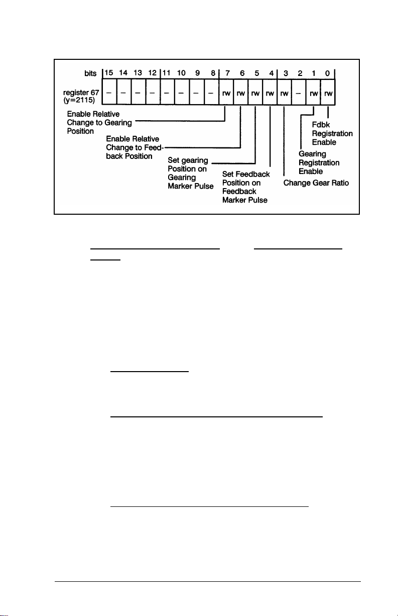
Figure 4.35 – Command Register 67
Feedback registration enable and/or gearing registration
enable is used to sense the respective registration digital
input. If the enable is set, any transition of the registration
input will cause the current gearing or feedback position to
be stored in registers 84 through 87. This is useful when
attempting to synchronize the axis to an external event. See
section 4. 31 for mo re optio ns regar ding re gistrat ion. Al so see
section 4.37 for a description of the "feedback registration
sensed" and "gearing registration sensed" bits (R72, b8 and
b9).
The change gear ratio
ratio set in 25/26 when you are running in the gearing mode.
This command can affect physical motion in the system.
The set feedback position on feedback marker pulse
command enables passive homing. This command does not
cause any motion. It only enables the logic such that when a
feedback marker pulse is detected, the value in registers 17,
18 is assigned to the axis feedback position. Marker pulses
are enabled in register 2. Note that there are other methods
of homing described in section 4.35.
The set gearing position on gearing mark er pulse
enables passive homing for the gearing encoder. On the next
gearing encoder marker pulse, the value in registers 17, 18 is
assigned to the axis gearing position. Marker pulses are
enabled in register 2. Note that there are other methods of
homing described in section 4.35.
PROGRAMMING
command is used to alter the gear
command
4-33
Page 62

The enable relative change to feedback position command
results in the value registers 17, 18 (the command position)
being added to the feedback position. This command only
causes the drive to change where it "thinks" it is. It does not
cause the drive to move.
The enable relative change to gearing position
results in the value in registers 17, 18 (command position)
being added to the gearing position. This command does not
cause the drive to move. It only causes the drive to change
where it “thinks” it is.
4.37 Register 72: St atus
Register 72 is the status register. This register is updated
continuously by the module, except during an auto-tune
operation. As soon as an auto-tune sequence is completed,
updating will begin. This register is read-only. Refer to figure
4.24. See 4.49 for more information on causing interrupts on
the corresponding status.
command
Figure 4.36 – Status Register
Axis done
4-34
status indicates whether the programmed motion
2-Axis Servo Module M/N 57C422B
Page 63

has been completed. It does not necessarily mean that the
axis is at the commanded position.
Axis locked
is set whenever the absolute value of the
difference between where the axis is and where it should be
is less than the value stored in the in-position register
(register 10). Note that the axis does not have to be stopped
to be in-position, and it may not be locked after an
incremental move.
Axis busy
The position > =
status is the logical complement of "axis done."
and position < bits work in conjunction with
the “sync position” contained in registers 29, 30 and the
“define sync position” command in register 66.
The home sequence complete
bit indicates whether a
homing sequence has been successfully completed. The bit
is reset by the module when it receives a “home axis”
command from register 66.
The auto tuning sequence
complete bit indicates whether an
auto tuning sequence is complete. This is the only status bit
that will be updated during auto-tuning. This bit will be set at
the end of an auto-tuning sequence regardless of whether it
was completed or aborted. The bit is reset by the module
when it receives an "auto tune" command.
The control loop enabled
bit indicates whether the control
loop (velocity/position) is actively regulating the drive. This bit
reflects the status of the control loop. The control loop is
disabled, and this bit is reset, by any severe fault, e.g., a
drive fault or hardware overtravel as reported in register 73.
The control loop is also disabled by turning off bit 0 in register
65.
The feedback registration sensed
feedback registration" command in register 67. The bit will be
set by the next occurrence of the feedback registration input,
and the feedback position will be stored in registers 84, 85.
This bit is not set unless the "feedback registration enable"
bit in register 67 is set first. The feedback registration sensed
bit stays high (1) until the "feedback registration enable" bit is
toggled.
The gearing registration sensed
gearing registration" command in register 67. The bit will be
PROGRAMMING
bit is reset by the "enable
bit is reset by the "enable
4-35
Page 64

set by the next occurrence of the gearing registration input,
and the gearing position will be stored in registers 86, 87.
This bit is not set unless the "gearing registration enable" bit
in register 67 is set first. The gearing registration sensed bit
stays high (1) until the "gearing registration enable" bit is
toggled.
The gearing marker sensed
bit is reset by the "reset gearing
position" command in register 66. If the gearing marker pulse
has been selected in register 2, the bit will be set by the next
occurrence of the gearing marker pulse.
The command acknowledge
bit is set by the module to
indicate that a command in either register 66 or 67 was
recognized by the module. When this bit is set, you should
clear the command in register 66 or 67.
4-36
2-Axis Servo Module M/N 57C422B
Page 65

4.38 Register 73: Fault
Register 73 is the fault register. This register is updated
continuously by the module except during an auto-tune
operation, when it will not be updated until the end of the
sequence. This register is read-only. Refer to figure 4.37.
See 4.49 for more information on causing interrupts on the
corresponding errors.
The overtravel
first enabled in register 2.
The maximum position error exce eded
following error in register 80 has exceeded the maximum
PROGRAMMING
Figure 4.37 – Fault Register
and drive fault bits can only be set if they are
bit is set when the
4-37
Page 66

position error specified in register 8. Note that this bit can
also be set when the axis is in the velocity mode. See 4.34
for more information about velocity mode.
The output clamped
generated by the module is greater than or equal to the value
in register 31. It does not turn the control off.
The feedback fault
due to a severe fault reflected in this same register (note that
bit 7 in this register is not considered a fault bit). The
feedback fault bit is also set if register 65, bit 0 is 0, i.e., the
control loop is not enabled.
The illegal command
command. An illegal command is an attempt to issue more
than one command (in registers 66 or 67) at the same time,
or providing illegal parameters for a command, e.g., an
acceleration rate of zero for a move command. This bit is
reset by writing a zero to registers 66 and 67.
The system fault
cold start, a STOP ALL / CLEAR command is issued from
the programming terminal, or a processor module fails. This
bit indicates that the communication between the processor
module and the axis module has been broken. When this
happens, feedback will be disabled, and the drive reference
will be set to zero.
bit indicates that the output reference
bit is set when the control loop is disabled
bit is set in response to an illegal
bit is set whenever the processor does a
4.39 Registers 74, 75: Current Feedback Position
Registers 74, 75 contain the current feedback position.
Registers 74, 75 are only updated when the "latch status"
command in register 66 is issued. This ensures that data will
be consistent while the application software interrogates it.
The units are encoder counts.
Figure 4.38 – Current Feedback Position Registers
4-38
2-Axis Servo Module M/N 57C422B
Page 67

4.40 Registers 76, 77: Current Geari n g Position
Registers 76, 77 contain the current gearing position.
Registers 76, 77 are only updated when the "latch status"
command in register 66 is issued. This ensures that data will
be consistent while the applicat ion softwa re inter rogates it.
The units are encoder counts. This data always originates
from the hardware gearing inputs on the given axis,
regardless of the selections made in register 65, bit 9, and
register 38, bits 0 and 1.
Figure 4.39 – Current Gearing Position Registers
4.41 Registers 78, 79: Current Velocity
Registers 78, 79 contain the current velocity i.e., the number
of counts in the period defined in R83. Registers 78, 79 are
only updated when the "latch status" command in register 66
is issued. This ensures that the data will be consistent while
the application software interrogates it. The units are
encoder counts.
Figure 4.40 – Current Velocity Registers
4.42 Register 80: Following Error
Register 80 contains the following error. Following error is
the difference between the internally commanded position
and the "current feedback position" in R74, 75. Register 80 is
only updated when the "latch status" command in register 66
is issued. This ensures that the data will be consistent while
PROGRAMMING
4-39
Page 68

the application software interrogates it.
Figure 4.41 – Following Error Register
4.43 Register 81: Velocity Error
Register 81 contains the velocity error. Velocity error is the
difference between the internally commanded velocity and
the current velocity. Register 81 is only updated when the
"latch status" command in register 66 is issued. This ensures
that the data will be consistent while the application software
interrogates it. Command (R66, b11) is issued. The units are
encoder counts/scan.
Figure 4.42 – Velocity Error Register
4.44 Register 82: Digital Input Status
Register 82 contains the digital input status. The values
reported in register 82 are the actual values of the inputs
without regard to the status of any bits contained in register
2. Refer to figure 4.43.
Figure 4.43 – Digital Input Status Register
4-40
2-Axis Servo Module M/N 57C422B
Page 69

4.45 Register 83: Current Velocity Status
Update Period
Register 83 contains the current velocity status update
period.
periods) during which data is accumulated before being
supplied to registers 78, 79 when the "latch status" command
is issued in register 66. The default value of R83 is 1, which
can actually be loaded as 0 or 1 into the register. Note that
this register is not accessed by the module until a "change
default setups" command is issued in R66.
This value is the number of scans (1.25 msec.
Figure 4.44 – Current Velocity Status Update Period Register
4.46 Registers 84, 85: Feedback Registration Position
Registers 84, 85 contain the feedback registration position.
The value in these registers is latched if the feedback
registration input is enabled (R72, b8) and the feedback
registration input is activated. The status is annuciated in
register 72, bit 8.
Figure 4.45 – Feedback Registration Position Registers
4.47 Registers 86, 87: Gearing Registration Position
Registers 86, 87 contain the gearing registration position.
The value in these registers is latched if the gearing
registration input is enabled (R72, b9) and the gearing
registration input is actuated. The status is annunciated in
PROGRAMMING
4-41
Page 70

register 72, bit 9.
This data always originates from the hardware gearing inputs
on the given axis, regardless of the selections made in
register 65, bit 9, and register 38, bits 0 and 1.
Figure 4.46 – Gearing Registration Position Registers
4.48 Registers 99- 103: Software Version
Number
Registers 99-103 contain the software version number as a
string of 10 ASCII characters. Refer to figure 4.47.
Figure 4.47 – Software Version Registers
4.49 Interrupt Registers
M/N 57C422A and later 2-Axis Servo modules support
hardware interrupts. A hardware interrupt is used to trigger
execution of some portion of an application task. The
hardware interrupt is level-sensitive (high = true).
The interrupt is implemented through an application task task
using the hardware EVENT statement. See the Enhanced
BASIC language instruction manual for more information on
hardware EVENT statements and the Control Block
language instruction manual for more information on Control
4-42
2-Axis Servo Module M/N 57C422B
Page 71

Block tasks.
Note that two of the registers used to implement interrupts,
64 (described in section 4.33) and 4095, are used for both
the X and Y axis. To avoid any confusion, at times this
section of the manual will not follow the general pattern of
notation found in the remainder of this instruction manual
and will explicitly refer to both the X and Y axis equivalents of
the register in question instead of only the X. In other words,
where the Y equivalent is given explicitly, you will not need to
add 2048 to the register number given for the X axis to find
the Y axis equivalent of the register number. Pairs of
registers that perform one function, such as enabling
interrupts, will be shown separated by a slash. For example,
registers 72/73 refers to all of the bits in registers 72 and 73
as a group.
4.49.1 Registers 68/69: Interrupt Enable
Registers 72 and 73 [X-axis] and 2120 and 2121 [Y-axis) are
read only registers that are used by the 2-Axis module to
report motion status and fault status for the two axes on a
continuous basis. You can choose to enable a hardware
interrupt whenever any bit in registers 72/73 or 2120/2121 is
set by the module. See section 4.37 and 4.38 for more
information on these status and fault registers.
To enable interrupts, the user application program must set a
bit or bits in registers 68/69, the interrupt enable masking
registers, that corresponds, respectively, to a bit or bits in
registers 72/73. For example, if you want to enable a
hardware interrupt whenever the “axis done” bit (0) in
register 72 is set by the system, set bit 0 in register 68 to
enable the interrupt. If you wanted to enable an interrupt
whenever the “velocity error exceeded” bit (5) in register 73
was set bit the system, you would set bit 5 in register 69.
You can set multiple bits in registers 68/69. Any bit or any
combination of those bits being set by the module in the
corresponding registers (72/73) will result in a hardware
interrupt. See figures 4.48 and 4.49.
PROGRAMMING
4-43
Page 72
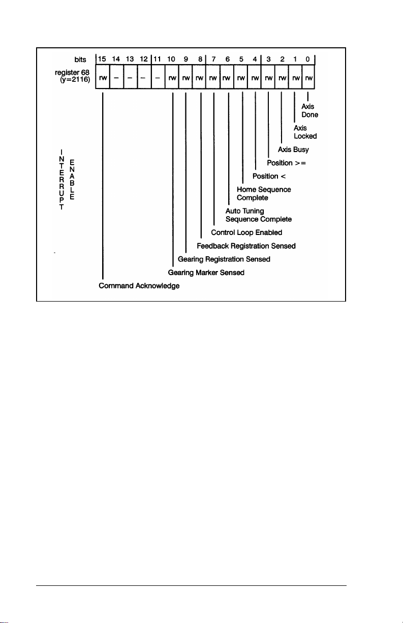
Figure 4.48 – Interrupt Enable Masking Register 68
4-44
2-Axis Servo Module M/N 57C422B
Page 73

Figure 4.49 – Interrupt Enable Masking Register 69
Bits in 68/69 can be set in one of two ways. All bits in the
registers can be defined separately in configuration and set
to 1 in application tasks. You can also define only the
registers in configuration and “mask”, the variables in
application tasks with BASIC statements AND or OR.
4.49.2 Registers 104/105: Interrupt Source
Registers 104/105 are the interrupt source registers and
correspond to registers 72/73 in the same manner as do
registers 68/69. A user application program should read
registers 104/105 to see which bit(s) were set after an
interrupt occurs, i.e. after the EVENT has been set. The
source of the interrupt is the corresponding bit(s) in registers
72/73. For example, to continue the example above in
4.49.1, if bit 5 in register 105 is set, the interrupt was caused
PROGRAMMING
4-45
Page 74

by the allowable velocity error being exceeded (bit 5 in
register 105 corresponds to bit 5 in register 73). After the
EVENT has been set, the user application task must write
zeroes to register 104/105. See figures 4.50 and 4.51.
Figure 4.50 – Interrupt Source Register 104
4-46
2-Axis Servo Module M/N 57C422B
Page 75

Figure 4.51 – Interrupt Source Register 105
4.49.3 Register 4095: Interrupt Status and Control
(ISCR) Register
Register 4095 is the interrupt status and control register for
both the X- and the Y-axis. This register is used by the
module to allocate and manage interrupts. The variable
name assigned to this register is used in the EVENT
statement.
Figure 4.52 – Interrupt Status and Control Register
PROGRAMMING
4-47
Page 76

4.49.4 Sample Application Task with Interrupt
The following sample application task illustrates the use of
interrupts on the 2-Axis module. This is not a complete
program, only a sample illustration using an interrupt. Note
that this sample assumes that the raw feedback from the
pulse generator is 1000 counts per revolution.
2000 LOCAL FDBK_SCALING
2010 LOCAL COMMAND%
2020 LOCAL DISTANCE
2030 LOCAL SPD
2040 LOCAL ACCEL
3000 INT_SRC_X! = 0 \! Initialize interrupt source
3010 INT_ENA_X! = 0 \! and enable registers and the
3020 REG_64% = 0 \! interrupt reset register;
3021 ! INT_SRC_X! and INT_ENA_X! are
3022 ! double precision variables
3023 !
3025 EVENT NAME=HW_EVENT, INTERRUPT_STATUS= ISCR%, &
TIMEOUT= DISABLED
3030 ! line 3025 connects the variable name ISCR% to the
3035 ! interrupt status and control register
3040 ENCODER_SETUP%=1414H \! X-Axis gearing and feedback
3042 ! encoders are in rotary
3045 ! w/ *4 quadrature
3050 DRIVE SETUP%=0H
3060 SWITCHES%=011CH \! enables drive fault input,
3065 ! overtravel L/S, feedback
3067 ! encoder marker pulse; home
3068 ! direction is in the decreasing
3069 ! position
3070 PGAIN%=17595
3080 IGAIN%=768
3090 VGAIN%=78
3100 FGAIN%=8320
3110 DBCOMP%=28
3120 MAX_FOLL_ERR%=2000 \! error is = to 0.5 axis revolutions
3130 MAX_VEL_ERR%=4000 \! 1 revolution of the axis
3140 IN_TOLERANCE%=10
3150 GEAR_RATIO!=0
3160 MAX_VOLTS%=1984 \! maximum volts = 10
3170 P_CONST%=-1
3180 N_CONST%=-1
3190 FDBK_UNWIND!=1600000 \! 400 axis revolutions
3200 GEAR_UNWINDI=4000 \! 4000 counts = 1 rev.
3201 ! from regs. 36,37
3210 COMMAND%=0200H \ GOSUB 15010 \! change default setups
3211 MODES% = 0
3215 DELAY 10 TICKS
3217 MODES% = 21H \! enable incremental index move
3218 ! and position loop
3230 FDBK_SCALING=4000 \DISTANCE=20 \ SPD =40.0 \ ACCEL = 50.0
4000 ! Index move
4010 CMD_POS! = FDBK_SCALING*DISTANCE
4020 CMD_VEL! = SPD*FDBK_SCALING*65.536
4030 CMD_ACC! = (ACCEL/4)*FDBK_SCALING*.065536
4040 CMD_DEC! = CMD_ACC!
4050 COMMAND% = 1 \GOSUB 15010
4055 !
4060 ! Subroutine to wait for axis done
4070 INT_ENA-X! = 00010000H
4080 WAIT ON HW_EVENT
4090 IF X_AXIS_DONE@ THEN INT_SRC_X! = 0 \ INT_ENA_X! = 0
4110 REG_64% = 0
4120 IF (INT_ENA_XI <> 0) THEN GOTO 4080
4130 GOTO 4010
4140 !
15000 ! Subroutine to wait for command ack
15010 INT_ENA_X! = INT_ENA_XI OR 80000000H
4-48
2-Axis Servo Module M/N 57C422B
Page 77

15014 ! line 15010 ORs INT_ENA_X! with 80000000H
15020 ! to enable interrupts from bit 15 of register 72
15030 CMD66% = COMMAND% \! loads value in COMMAND% into CMD66%
15032 ! which is the first command
15034 ! register on the X axis
15040 WAIT ON HW_EVENT
15042 ! after seeing the hardware event occur, test to see
15044 ! which interrupt occurred; if more than one interrupt
15046 ! is enabled, each must be chocked to see what caused
15048 ! the interrupt.
15049 !
15050 IF X_CMD_ACK@ THEN INT_SRC_X! = 0 \ INT_ENA_X! = 0 \ CMD66% = 0
15052 ! waiting on the hardware event here ensures that the
15054 ! Axis module responds with a command acknowledge
15056 ! before anything else is allowed to occur.
15060 !
15070 REG_64% = 0 \! reset interrupts (reg 64 for both X and Y)
15080 IF (INT_ENA_X! <> 0) THEN GOTO 15040
15082 ! line 15080 checks for an interrupt on the X axis
15090 RETURN
4.50 Cam Registers
The following sections describe how to implement the cam
profile registers. Two types of cam tables are available,
position-based, and time-based. The values in the cam table
are signed integers. These values represent either the
relative change in position for successive intervals of time in
the time-based cam, or the position of the axis with respect
to a master reference position in registers 126,127 if the
position-based cam is selected. Cam type is selected in
register 130, bit 8. The number of positions actually stored in
both the time-based cam and the position-based cam table is
defined in register 128.
Time Cam
The time-based cam table can be stored either as bytes or
words (16 bit registers). Byte values may range from -128 to
127 in encoder counts and are packed two per register. The
lower numbered byte is stored as the least significant 8 bits
of the register. There are a maximum of 3830 byte values in
the table. Note that if you use the byte format, you cannot
configure the values in the cam table in a configuration task
or in the Programming Executive variable configurator
application. You must use BASIC IOWRITE statements to
write the values to the cam table within your application
program.
Word values may range from -32768 to 32767 in encoder
counts. There are a maximum of 1915 word values in the
table. The values in the table represent the distance to move
in the selected amount of time.
PROGRAMMING
4-49
Page 78

In order to select the value format (bytes or words), you need
to consider the number of points that are required to
represent the profile and the largest value that will be
required. In general, a profile can be described more
accurately with more points. The largest value that can be
stored in the table when time cam is selected can be
calculated using the following equation:
largest value = speed * encoder * time * .00125
where: speed = max. axis velocity in eng. units/sec
encoder = encoder counts/eng. unit
time = the value in register 129
If the absolute value of the above calculation exceeds 127,
you must choose the word format.
Position Cam
Register 38, bits 0 and 1 define what the axis will follow for
the purposes of position-based cam. Register 125 selects
the master axis position increment, i.e., the amount of travel
the master moves to increment to the next position in the
table, thus resulting in all points being the same distance
apart. Position cam values must be in double precision
integer format (32 bit values). Note that there are 956 total
points possible. For the X axis, register 2044, 2045 is the last
possible point in the cam table. For the Y axis, register 4092,
4093 is the last possible point in the cam table.
Linear Mode: When the master axis and the axis under
control are configured for linear mode in register 0, the
position cam operates in linear mode. In this mode, the first
point in the table should have a value of 0.
4-50
2-Axis Servo Module M/N 57C422B
Page 79

When the master axis moves past the master reference
position, the following axis saves its own current position as
the base position. It then adds the position from the cam
table to the base position to arrive at the absolute position at
which it should be, using linear interpolation between points.
Rotary Mode with Endpoints Equal: When the master axis
and the axis under control are configured for rotary mode in
register 0, but the rotary position cam endpoints bit in register
130 is set to 0, the position cam will actually operate in linear
mode. The beginning and ending points of the table must be
equal and all positions in the table must be positive and less
than the unwind constant. After the master reaches the
unwind point, the following axis will repeat the cam motion.
The motion of the axis under control must be completed
before the master axis reaches the unwind position. If the
master axis runs in reverse, the position cam will work
backwards through the table. The cam will continue to
execute even if the master axis backs up behind the master
reference position.
PROGRAMMING
4-51
Page 80
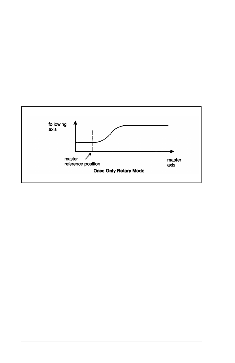
Once Only Rotary Mode: When the master axis and the
axis under control are configured for rotary mode in register
0, the rotary position cam endpoints bit in register 130 is set
to 1, and the run mode bit is set to 0, the position cam will
operate in the rotary mode once only. In this mode, the
beginning and ending points of the table do not need to be
equal. After the cam is enabled and the master axis moves
past the master reference position, the cam is executed
once. To enable the cam to run again, the "do cam profile"
command must be issued again. When re-enabling the cam,
you must ensure that the master axis is behind the master
reference position.
Continuous Rotary Mode: When the master axis and the
axis under control are configured for rotary mode in register
0, the rotary position cam endpoints bit in register 130 is set
to 1, and the run mode bit in register 130 is set to 1, the
position cam will operate in continuous rotary mode. In this
mode, the beginning and ending points of the table do not
need to be equal. After the cam is enabled and the master
axis moves past the master reference position, the cam is
executed once. Then, whenever the master unwinds, the
following axis will execute the cam again from its current
position. If the master axis runs in reverse, the position cam
will work backwards through the table. The cam will continue
to execute even if the master axis backs up behind the
4-52
2-Axis Servo Module M/N 57C422B
Page 81

master reference position.
Each point in the position cam table consists of four bytes
(double precision integers). There are a maximum of 956
positions in the table if position cam is selected.
4.50.1 Register 125: Master Axis Position Increment
Register 125 is used to store the master axis position
increment (in counts) for the position cam. This value selects
the number of counts the master axis moves to increment to
the next position in the position cam table. This value cannot
be a negative number. This value must not exceed 32767. All
points in the table are the same distance apart.
Figure 4.53 – Master Axis Position Increment Register
4.50.2 Registers 126, 127: Master Reference Position
Registers 126 and 127 are used to store the master axis
position for the position cam. This double precision integer
selects the position for the master at which the cam will
enable movement of the following axis. Before the position
cam can be enabled, the master axis must be behind the
master reference position. In rotary mode, the master
reference position must be less than the unwind limit or the
PROGRAMMING
4-53
Page 82

cam will never be started. The value is in counts.
Figure 4.54 – Master Reference Position
4.50.3 Register 128: Number of Points in Cam Table
Register 128 is used to select the number of points in the
cam table that are filled-in. This number represents bytes or
words for a time cam profile or double precision integers for a
position cam table. This register is read by the module
whenever the "do cam profile" bit is set in register 66.
Attempts to modify register 128 while the axis is moving will
be ignored by the module. See figure 4.55.
4.50.4 Register 129: Time Between Points in Cam
Table
Register 129 defines the time between points in the cam
table. The unit is scans. The time can be calculated with the
following equation:
Time = cam cycle time
number of profile points in the cam table * .00125
The time must be greater than or equal to 1. See figure 4.55.
4.50.5 Register 130: Cam Mode
Register 130 is used to select setup information about both
time and position type cams and to enable the position cam.
If position cam is selected, only bits 3 and 7 are used. See
figure 4. 55.
The data format
as either bytes or words.
If the table direction
the lowest register (132) to the highest defined register
(<=2046) in sequence. If it is set to reverse, the cam will
move from the highest defined register ( <=2046) to the
4-54
bit defines the data in the cam profile table
bit is set to forward, the cam moves from
2-Axis Servo Module M/N 57C422B
Page 83

lowest register (132) in sequence. As a general rule, the
table should be accessed forward unless it is necessary to
exactly reverse a motion. In this case, the reverse direction
would be specified along with a negative motion direction.
If the run mode
bit is set to 0, the cam profile is executed
once according to the settings of the other cam mode bits.
The loopback register (131) is not used. If "run mode" is set
to 1, the time cam profile will be executed continuously
according to the settings of the other cam mode bits. At the
end of a time cam cycle, the module will return to the point
defined in the loopback register (131). The position cam
does not use register 131. See 4.50 for more information.
If the mirror image
bit is set, the module will start with the
data in register 132 and automatically reverse direction when
the last point in the table is reached and continue back to the
beginning. If "continuous mode" was selected (bit 5), the
mirror will be between the last point in the table and the
loopback point. If the cam is only executed once, the mirror
will be from the last point in the table to register 132. This
feature allows symmetrical profiles (like sine and cosine) to
be defined with only half of the data points.
The motion direction
bit determines the direction that the axis
will move when the cam profile is executed. If the direction is
positive, the axis will move in the same direction as the sign
of the cam profile points. If the direction is negative, the axis
will move in the opposite direction as the sign of the cam
profile points.
The rotary position cam end point
bit is used to select the
cam table beginning/ending points if the rotary mode is
selected. The default (0) means the beginning and ending
points must be equal. Setting the bit to 1 means the end
points may or may not be equal. See 4.50 for more
information.
The cam type
cam. If position cam is selected (bit 8=1) then only bits 3 and
7 of the remaining bits in the register apply.
PROGRAMMING
bit is used to select either the position or time
4-55
Page 84

Figure 4.55 – Cam Profile Registers
4.50.6 Register 131: Loop Back Point in Cam Table
Register 131 contains the loop back point in the time cam
profile. This register is not used when position cam is
selected. The loop back point is the profile point to which the
axis will return after reaching the end of the defined profile. If
this register is used, you must ensure that both the value for
the last point in the cam profile table and the value for the
loopback point are within the accel/decel capability of the
servo drive. The profile points between the first profile point
and the loop back point are executed only once even in the
continuous mode. This allows these initial profile points to be
used to accelerate the axis into and out of the profile. The
loopback register is not used if the cam profile is executed
only once. Note that the first point in the cam table is point
zero (0). Refer to figure 4.56.
4-56
2-Axis Servo Module M/N 57C422B
Page 85

Figure 4.56 – Cam Loop Back Register
4.50.7 Cam Data Registers
Cam data is stored in registers 132-2046 for the X axis
and in registers 2180-4094 for the Y axis. The number of
points within this register range depends upon
usable
whether you have selected time cam or position cam via
register 130, bit 8.
Time cam data is stored either as single precision integers
(16 bits, i.e., one register) or as bytes (8 bits). The largest
number of points that can be defined for a time cam is 1915 if
stored as registers, and 3830 if stored as bytes. See figure
4.57 for the first and last possible points that can be defined
for a time cam.
Position cam data is stored as double precision integers (32
bits, i.e., two registers), with the even number register being
the lower order 16 bits. The largest number of points that can
be defined for a position cam is 956. See figure 4.58 for the
first and last possible points that can be defined for a position
cam.
For both the time and position cam modes, the total number
of points that is defined must be specified in registers 128 for
the X axis and in register 2176 for the Y axis. The values in
the table must be in the proper format. See section 4.50 and
4.50.5 for more information.
PROGRAMMING
4-57
Page 86

Figure 4.57 – Time Cam Data Registers
Figure 4.58 – Position Cam Data Registers
4-58
2-Axis Servo Module M/N 57C422B
Page 87

CHAPTER 5
APPLYING THE MODULE
5.1 Required Syst em Information
Before attempting to use this module you will need to know
the following information about your existing hardware:
1. Motor/Drive Regulator
- Maximum velocity
- Current or speed regulation in the drive. If the drive is
a speed regulator, does it use a proportional + integral
control?
- Maximum voltage for full scale reference to the drive
2. Encoder(s)
- Mode (step/direction, stepper motor, *2 quad, or *4
quad)
- Pulses/rev
- Whether marker pulse will be used for homing
3. System
- Mechanical gear-in (inches of travel/encoder
revolution
- Whether limit switches will be used for home,
overtravel, and drive fault. If so what is sense of limit
switches (normally open or closed)?
- If using gearing, what is the gear ratio between the two
axis?
5.2 T uning
Before attempting to use the 2 Axis module in your
application, you should first tune the drive. This can either be
done manually or with the auto-tuning procedures supplied
on the application disk that came with your ReSource
APPLYING THE MODULE
5-1
Page 88

software.
5.2.1 Auto-Tuning
The auto-tuning procedure on the application disk should
work satisfactorily if the following conditions apply:
1. The feedback encoder is connected to the motor shaft.
2. You have a servo drive with reasonable performance
characteristics.
3. You have a mechanical system that can move in both
directions.
4. The motor is able to run at or near maximum velocity for
a number of revolutions (for the purposes of auto-tune
dynamics and feedforward gain).
5.2.2 Manual Tuning
If auto-tuning does not yield satisfactory performance or your
system does not permit auto tuning you will need to tune
your system manually. The five gain parameters must be
adjusted in the following order:
1. Deadband Compensation (set to zero)
2. Velocity Gain
3. Proportional Gain
4. Integral Gain
5. Feedforward Gain
In general, each parameter is tuned by starting with a small
value, evaluating the response of the system, and then
increasing the value until the desired response is achieved.
Once a gain has been tuned, it should be left at its tuned
value and the next gain should be adjusted.
Use the following steps to tune the axis manually. When
adjusting gains, double or halve the previous value,
whichever is appropriate, until you are close to the desired
gain. Then use smaller increments to reach the precise
5-2
2-Axis Servo Module M/N 57C422B
Page 89

value.
WARNING
RELIANCE STRONGLY RECOMMENDS THE USE OF AN
EXTERNAL, HARDWIRED EMERGENCY STOP CIRCUIT THAT
WILL DISABLE THE SYSTEM IN CASE OF IMPROPER
OPERATION. UNCONTROLLED MACHINE OPERATION MAY
RESULT IF THIS PROCEDURE IS NOT FOLLOWED. FAILURE
TO OBSERVE THIS PRECAUTION COULD RESULT IN BODILY
INJURY.
1. Initialize the axis using either the Resource application
software (see step 16 in section 5.3) or by following the
example in 4.3.3. Set the gains to the following initial
values.
Proportional Gain = 100
Integral Gain = 0
Ve locity Gain = 25*
Feedforward Gain = 0
*If the servo is expecting a velocity reference, set to 0
instead.
Set the following error and velocity error to large values
that will ensure safe operation of the machine without
nuisance faults, and then enable feedback (register 65,
bit 0).
2. If the servo is expecting a velocity reference, the
software velocity loop in the module is disabled and the
velocity gain does not need to be tuned. You can skip
steps three and four if the servo is expecting a velocity
reference.
3. If the servo is expecting a current reference, you will
need to put the drive in the velocity mode (register 65, bit
0) with velocity to set approximately half of the maximum
speed that your application will run at.
If the drive trips out with a following error (indicted in
register 73, bits 4 or 5), the initial value of the
proportional gain is too low. Double it and repeat the step
until the drive runs continuously.
APPLYING THE MODULE
5-3
Page 90

4. Next, adjust the velocity gain. Continue to increase the
gain and observe the motor shaft. Ideally, the shaft
should regulate with very little noise or vibration. When
the shaft begins to vibrate, reduce the gain until the shaft
becomes relatively quiet.
Run the drive in the velocity mode at half of top speed.
The velocity error should be nearly zero (indicated in
register 81). Stop the drive. When the drive is stopped, it
should stop smoothly and cleanly.
5. Adjust the final value of the proportional gain. Continue
to increase the gain and observe the motor shaft. Ideally,
the shaft should regulate with very little noise or
vibration. When the shaft begins to vibrate, reduce the
gain until the shaft becomes relatively quiet.
Run the drive in the velocity mode at half of top speed.
The velocity error should be nearly zero (indicated in
register 81). Stop the drive. When the drive is stopped, it
should stop smoothly and cleanly.
6. Start with an integral gain of 10 and observe the motor’s
response as you attempt to make small incremental
moves. The integral gain will enable the shaft to hold a
rest position with zero error. A gain that is too large will
cause instability.
7. If you are using a servo drive that expects a velocity
reference and it contains an integrator in its a velocity
loop, the feedforward gain should be set at zero.
For all other drives, start with a gain of zero and run the
axis at or near its maximum velocity. Read the following
error (indicated in register 80). Increase the gain until the
following error as small as possible without going
negative.
8. Set the following error and velocity error to reasonable
values for your application.
5-4
2-Axis Servo Module M/N 57C422B
Page 91

5.3 Initialization
The following example illustrates the software required to
initialize one axis. The variables reference the configuration
data in Appendix H.
1000 !
1010 ! Initialize Axis Parameters
1020 !
2000 ENCODER_SETUP%=01414H\!Rotary, polarity reversed, *4
2010 DRIVE_SETUP%=02H \!Polarity reversed, current ref
2020 SWITCHES%=01DH \!Marker pulse, home negative
2030 PGAIN%=18700 \!Position Gain
2040 IGAIN%=1575 \!Integral Gain
2050 VGAIN%=140 \!Velocity Gain
2060 FGAIN%=8256 \!V Feedforward Gain
2070 DBCOMP%=27 \!Deadband Compensation
2080 MAX_FOLL_ERR%=1000 \!Maximum following error
2090 MAX_VEL_ERR%=8 \!Maximum velocity error
2100 IN_TOLERANCE%=40 \!In position tolerance
2110 GEAR_RATIO!=16777216 \!Gear ratio
2120 MAX_VOLTS%=1984 \!Maximum drive reference value
2130 P_CONST%=-1 \!Positive linearization constant
2140 N_CONST%=-1 \!Negative linearization constant
2150 FDBK_UNWIND!=4000 \!V Fdbk unwind = 1 revolution
2160 GEAR_UNWIND!=4000 \!Gearing unwind = 1 revolution
2170 MODES%=0
2180 CMD66%=0200H\GOSUB 25000\!Change default setups
2190 !
10000 !
24997 !
24998 ! Subroutine to write command to module
24999 !
25000 DELAY 2 TICKS \IF NOT (CMD_ACK@ OR ILLEGAL_CMD@)
25005 FAULT
25010 CMD66%=0 \CMD67%=0
25015 DELAY 2 TICKS \IF CMD_ACK@ THEN GOTO 25015
25020 RETURN
30000 END
THEN GOTO 25000
@=
ILLEGAL_CMD@
APPLYING THE MODULE
5-5
Page 92

5.4 Homing
The following is a sample routine that will home the axis. If
the setup parameters defined in section 5.3 are used, the
axis will first move in the direction of decreasing encoder
counts (negative) towards the home limit switch. After the
home limit switch has been tripped, the axis will then move at
slow speed in the opposite direction until it reaches the
marker pulse. This same routine will correctly perform all of
the other home sequences based on the configuration data
in register 2.
4991 !
4992 ! Homing Sequence
4993 !
4994 ! FDBK-SCALING = encoder counts/engineering unit
4995 ! FDBK-POS = position (in engineering units)
4996 ! SPD = velocity (in engineering units)
4997 ! ACCEL = acceleration (in engineering units)
4998 ! FAULT@ = fault status
4999 !
5000 HOME_SPD!=(SPD/100.)*FDBK_SCALING*65.536 \!Slow home velocity
5010 CMD_POS!=FDBK_POS*FDBK_SCALING \!Home position
5020 CMD_VEL! =(SPD/10.)*FDBK_SCALING*65.536 \!Fast home velocity
5030 CMD_ACC!=(ACCEL/4.)*FDBK_SCALING*.065536 \!Maximum accel
5040 CMD_DEC!=CMD_ACC! \!Maximum decel
5050 MODES%=MODES% AND 0FE
5060 DELAY 10 TICKS
5070 MODES%=MODES% OR 1 \!Enable fdbk loop
5080 CMD66%=4 \GOSUB 25000 \!HOME COMMAND
5090 IF FAULT@ THEN RETURN
5100 DELAY 20 TICKS VF NOT HOME_COMPLETE@ THEN GOTO 5100
5110 DELAY 20 TICKS
5120 FAULT@= (FAULTS% AND 037FH) < > 0
5130 RETURN
H \!Disable fdbk
5-6
2-Axis Servo Module M/N 57C422B
Page 93

5.5 Moving
The following example illustrates the software required to
move the axis. The move could be either an incremental or
absolute move depending on the state of register 65, bit 5.
5990 !
5991 ! Move Sequence
5992 !
5993 ! FDBK_SCALING = encoder counts/engineering unit
5994 ! FDBK_POS = position (in engineering units)
5995 ! SPD = velocity (in engineering units)
5996 ! ACCEL = acceleration (in engineering units)
5997 ! DECEL = deceleration (in engineering unit s)
5998 ! FAULT@ = fault status
5999 !
6000 CMD_ POS!=FDBK_PO S*FDBK_SCALING
6005 CMD_VEL!=SPD*F D BK_SCALING*65.536
6010 CMD_ACC!=ACCEL*FDBK_SCALING* .065536
6015 CMD_DEC!=DECEL*FDBK _SCALING*.065536
6020 CMD66%= 1 \GOSUB 25000 \IF F AULT@THEN RETURN
6047 REM
6D48 REM Loop until MOVE complete or a fault occurs
6049 REM
6050 DELAY 20 TICKS \IF AXIS_BUSY@ THEN GOTO 6050
6055 FAULT@=(FAULTS% AND 037FH)<>0
6060 RETURN
APPLYING THE MODULE
5-7
Page 94

5.6 Elect ronic Gearing
The following example illustrates the software necessary to
use electronic gearing. Three examples are provided, one
each for turning the gearing mode on, changing the gear
ratio while the drive is active, and turning the gearing mode
off.
6992 !
6993 ! Turn on gearing mode
6994 !
6995 ! FDBK_SCALING = feedback encoder counts/engineering unit
6996 ! REF_SCALING = gearing encoder counts/engineering unit
6997 ! GEAR = gear ratio
6998 ! GEAR_DIR_SAME@ = gear dir ection switch
6999 !
7000 GEAR_RATIO!=(FDBK_SCALING*GEAR/REF_SCALING\ *65536.*256.
7005 MODES%=MODES% AND 0ADH
7010 IF NOT GEAR_DIR_SAME@ THEN MODES%= MODES% OR 010H
7015 MODES%=MODES% OR 2
7020 RETURN
7100 !
7293 !
7294 ! Change gear ratio while drive is active
7295 !
7296 ! FDBK_SCALING = feedback encoder counts/engineering unit
7297 ! REF_SCALING = gearing encoder counts/engineering unit
7298 ! GEAR = gear ratio
7299 !
7300 GEAR_RATIO!=(FDBK_SCALING*GEAR/REF_SCALING) *65536.*256.
7305 CMD67%=8 \GOSUB 25000
7310 RETURN
7400 !
7497 !
7498 ! Turn off gearing mode
7499 !
7500 MODES%= MODES% AND 0ADH
7505 RETURN
5-8
2-Axis Servo Module M/N 57C422B
Page 95

5.7 Velocity
The following example illustrates the software necessary to
use the axis in the velocity mode. Three examples are
provided, one each for turning velocity on, changing the
velocity while the drive is active, and turning velocity off.
7991 !
7992 Turn on velocity mode
7993 !
7994 ! FDBK_SCALING = encoder counts/engineering unit
7995 ! SPD = velocity (in engineering units)
7996 ! ACCEL = acceleration (in engineering units)
7997 ! DECEL = decelerat ion (in engineering units)
7998 FAULT@ = fault status
7999 !
8000 MODES%=MODES% AND 0AFH
8005 IF SPD < 0. THEN MODES%=MODES% OR 01 OH \SPD=-SPD
8047 REM
8048 REM Issue VELOCITY command to axis
8049 REM
8050 CMD_VEL!=SPD*FDBK_SCALING*65.536
8055 CMD_ ACC!=ACCEL*FDBK_SCALING*. 065536
8060 CMD_DEC! =DECEL*FDBK_SCALING*.065536
8065 MODES%=MODES% OR 4
8070 FAULT@= (FAULTS% AND 037FH) < > 0
8075 RETURN
8100 !
8294 !
8295 ! Change velocity while drive is running
8296 !
8297 ! FDBK_SCALING = encoder counts/engineering unit
8298 ! SPD = velocity (in engineering units)
8299 !
8300 IF SPD < 0. THEN SPD=-SPD
8305 CMD_VEL!=SPD*FD BK_SCALING*65.536
8310 CMD66%=0100H \GOSUB 25000
8315 RETURN
8400 !
8497 !
8498 ! Turn off velocity mode
8499 !
8500 MODES%=MODES% AND 0BBH
8505 RETURN
APPLYING THE MODULE
5-9
Page 96

5.8 Cam Mode
The following example illustrates the software necessary to
use the axis in the cam mode. The example is a time cam. It
illustrates how to calculate cam parameters and the values in
the cam table itself. It also shows how to start cam execution.
8992 !
8993 ! Compute cam parameters
8994 !
8995 ! FDBK_SCALING = encoder counts/engineering unit s
8996 ! CAM_CYCLE_TIME = time (in seconds) for one complete
8997 ! SPD = maximum speed (in engineering units)
8998 ! MAX_SPD = maximum speed (encoder counts/cam
8999 !
IF CAM_CYCLE_TIME <1915*.00125 THEN STEP_TIME=1 \GOTO 9010
9000
9005 STEP_TIME%=CAM_CYCLE_TIME/(1915*.00125)+.999
9010 TOTAL_PTS%=CAM_CYCLE_TIME/(STEP_TIME%*.00125)+.999
9015 IF TOTAL_PTS% > 1915 THEN TOTAL_PT S%= 1915
9020 MAX_SPD=SPD*FDBK_SCALING*ST EP_TIME%*.00125
9025 RETURN
9297 !
9298 ! Calculate Cam Profile Points
9299 !
9300 ADDRESS!=VARPTR!(CAM_TABLE%) \!Starting address for cam profile
9310 FOR I%=0 TO TOTAL_PTS%_1
9315 ! DATA_POINT%=change in position for next time interval
9320 IOWRITE(3, DATA_POINT%, ADDRESS!)
9325 ADDRESS!=ADDRESS! +2
9330 NEXT I%
9335 RETURN
9400 !
9497 !
9498 ! Start cam cycle
9499 !
9500 CAM_LOOPBACK%=0 !No loopback point.
9505 CAM_MODE%=9 \!Run continuously, word format
9510 CMD66%=080H \GOSUB 25000 \! Do cam profile
9515 RETURN
cam cycle
time interval)
5-10
2-Axis Servo Module M/N 57C422B
Page 97

This section describes limitations and restrictions on the use
of this module.
6.1 Remote Racks
This module must not be used in a remote rack.
CHAPTER 6
RESTRICTIONS
RESTRICTIONS
6-1
Page 98

6-2
2-Axis Servo Module M/N 57C422B
Page 99

APPENDIX A
Technical Specifications
Ambient Conditions
• Storage Temperature: -40oC - 85oC
o
• Operating Temperature: 0
• Humidity: 5-90% non-condensing
Maximum Module Power Dissipation
• 8 Watts average
Dimensions
• Height: 11.75 inches
• Width: 1.25 inches
• Depth: 7.375 inches
System Power Requirements
C - 60oC
• +5 Volts: 1.6 Amps average
• +12 Volts: 100 mA per axis channel*
• -12 Volts: 100 mA per axis channel*
12 Volts supplied externally by the user for
•+
isolation
Encoder Specifications
• Signal type: Differential CMOS or TTL
• Signal level: 5 Volts
• Maximum input current: 4.5 mA
• Maximum frequency: 250 khz/channel
A-1
Page 100

Registration Input Specifications
• Signal type: Electronic
• Maximum operating voltage: 24 Volts D-C ±20%
• Maximum ON current: 6 mA
• Transport delay: 50 microseconds
Limit Switch Input Specifications
• Signal Type: Contact or electronic
• Maximum operating voltage: 24 Volts A-C or D-C ±20%
• Maximum ON current: 6 mA
• Input Filter: 30 Hz
Watchdog Output Specifications
• Signal Type: Contact
• Signal level: 5-24 volts A-C or D-C
• Curr ent rating: 1000 mA max
Drive Reference Specifications
• Signal range: +10 Volts into a 10K ohm load
External Encoder Power Supply
• Voltage: +5 VDC
• Current: 250 mA + encoder requirements
• Regulation: 1%
Drive Reference Power Supply Specifications
• Voltage: ±12 to +15 VDC
• Curr ent: 25 mA
• Regulation: .1%
Scan Time
• 1.25 msec. update rate for velocity and position loops
A-2
2-Axis Servo Module M/N 57C422B
 Loading...