

Page 1

AutoMaxrPower Supply
Modules and Racks
M/N 57C493 Power Supply Module
M/N 57C494 Power Supply Module
M/N 57C331 16ĆSlot Rack
M/N 57C332 10ĆSlot Rack
M/N 57C334 6ĆSlot Rack
Instruction Manual J2Ć3008Ć4
Page 2
DANGER
ONLY QUALIFIED ELECTRICAL PERSONNEL FAMILIAR WITH THE
CONSTRUCTION AND OPERATION OF THIS EQUIPMENT AND THE HAZARDS
INVOLVED SHOULD INSTALL, ADJUST, OPERATE, OR SERVICE THIS
EQUIPMENT. READ AND UNDERSTAND THIS MANUAL AND OTHER
APPLICABLE MANUALS IN THEIR ENTIRETY BEFORE PROCEEDING. FAILURE
TO OBSERVE THIS PRECAUTION COULD RESULT IN SEVERE BODILY INJURY
OR LOSS OF LIFE.
DANGER
THE USER IS RESPONSIBLE FOR CONFORMING WITH ALL APPLICABLE
LOCAL, NATIONAL, AND INTERNATIONAL CODES. WIRING PRACTICES,
GROUNDING, DISCONNECTS, AND OVERĆCURRENT PROTECTION ARE OF
PARTICULAR IMPORTANCE. FAILURE TO OBSERVE THIS PRECAUTION
COULD RESULT IN SEVERE BODILY INJURY OR LOSS OF LIFE.
WARNING
INSERTING OR REMOVING THE POWER SUPPLY MODULE OR ITS
CONNECTING CABLES MAY RESULT IN UNEXPECTED MACHINE MOTION.
POWER TO THE MODULE SHOULD BE TURNED OFF BEFORE INSERTING OR
REMOVING THE MODULE OR ITS CONNECTING CABLES. FAILURE TO
OBSERVE THIS PRECAUTION COULD RESULT IN BODILY INJURY.
WARNING
THE USER MUST PROVIDE AN EXTERNAL, HARDWIRED EMERGENCY STOP
CIRCUIT OUTSIDE THE PROGRAMMABLE CONTROLLER CIRCUITRY. THIS
CIRCUIT MUST DISABLE THE SYSTEM IN CASE OF IMPROPER OPERATION.
UNCONTROLLED MACHINE OPERATION MAY RESULT IF THIS PROCEDURE IS
NOT FOLLOWED. FAILURE TO OBSERVE THIS PRECAUTION COULD RESULT IN
BODILY INJURY.
CAUTION: The power supply module and racks contain staticĆsensitive components.
Careless handling cancause severe damage. Do nottouch the connectors ontheback
of the power supply module or the racks. When not in use, the power supply module
should be stored in an antiĆstaticbag. The plasticcover should not be removed. Failure
to observe this precaution could result in damage to or destruction of equipment.
Allen-Bradley and Rockwell Automation are trademarks of Rockwell Automation, Inc,.
Trademarks not belonging to Rockwell Automation are property of their respective companies.
Page 3

Table of Contents
1.0 Introduction 1Ć1...............................................
1.1 Additional Information 1Ć1....................................
1.2 Related Hardware and Software 1Ć2...........................
2.0 Mechanical/Electrical Description 2Ć1...........................
2.1 Power Supply Module Mechanical Description 2Ć1.........
2.1.1 Power Supply Module LED Indicators 2Ć4.................
2.1.2 Power Supply Module Terminal Block 2Ć4.................
2.1.3 Power Supply Module Battery Connection
(M/N 57C493 only) 2Ć4.................................
2.1.4 Power Supply Module Keyswitch 2Ć4.....................
2.2 Power Supply Module Electrical Description 2Ć5.................
2.3 Rack Mechanical Description 2Ć5..............................
2.4 Rack Electrical Description 2Ć6................................
3.0 Installation 3Ć1................................................
3.1 Wiring 3Ć1..................................................
3.2 Initial Installation 3Ć1.........................................
3.3 Power Supply Module Replacement 3Ć5........................
3.4 Rack Replacement 3Ć6.......................................
4.0 Diagnostics and Troubleshooting 4Ć1............................
4.1 The POWER LED Is Off 4Ć1...................................
4.2 The FAULT LED is On 4Ć2....................................
I
Page 4

Appendices
Appendix A
Technical Specifications AĆ1......................................
Appendix B
External Connections BĆ1........................................
Appendix C
Rack Backplane CĆ1............................................
Appendix D
Rack Mounting Pattern DĆ1.......................................
Appendix E
Power Requirements of AutoMax Modules EĆ1.....................
II
Page 5

List of Figures
Figure 2.1 Ć 376W Power Supply Module (M/N 57C493) 2Ć2................
Figure 2.2 Ć 147W Power Supply Module (M/N 57C494) 2Ć3................
Figure 2.3 Ć 6ĆSlot Rack 2Ć6............................................
Figure 2.4 Ć 10ĆSlot Rack 2Ć6...........................................
Figure 2.5 Ć 16ĆSlot Rack 2Ć7...........................................
Figure 2.6 Ć Rack Slot Limitations 2Ć7....................................
Figure 2.7 Ć Typical Input Power Connections 2Ć8.........................
III
Page 6

Page 7

1.0 INTRODUCTION
The products described in this instruction manual are manufactured
by Reliance Electric Industrial Company.
The Power Supply module (M/N 57C493 or M/NĂ57C494) converts
115 VAC input power into the DC voltages necessary to operate the
other modules contained in the Rack. The Rack provides the
mechanical means of mounting 6 (M/N 57C334), 10 (M/NĂ57C332),
or 16 (M/NĂ57C331) DCS 5000 or AutoMax modules, as well as the
Power Supply module. The Multibust backplane in the Rack
provides two sets of bus lines for local communication among the
DCS 5000 and AutoMax modules.
The M/N 57C393 Power Supply module can provide a maximum
continuous output of 376 watts to power modules in the AutoMax
rack. The M/N 57C394 Power Supply module can provide a
maximum continuous output of 147 watts to power modules in the
AutoMax rack. When using the M/N 57C494 Power Supply module in
a 10 or 16Ćslot rack, make certain that the power requirements of the
modules in the rack do not exceed the capacity of the Power Supply
module. See Appendix E for a list of AutoMaxĆcompatible modules
and their power requirements.
This instruction manual describes the functions and specifications of
the Power Supply modules and the Rack. It also includes a detailed
overview of installation and servicing procedures.
1.1 Additional Information
You should be familiar with the instruction manuals which describe
your system configuration. This may include, but is not limited to, the
following:
D JĆ3636 COMMON MEMORY MODULE INSTRUCTION MANUAL
D JĆ3649 AutoMax CONFIGURATION TASK MANUAL
D JĆ3630 ReSource AutoMax PROGRAMMING EXECUTIVE
D JĆ3650 AutoMax PROCESSOR MODULE INSTRUCTION
D JĆ3668 DCS 5000 POCKET REFERENCE
D JĆ3669 AutoMax POCKET REFERENCE
D JĆ3675 AutoMax ENHANCED BASIC LANGUAGE
D JĆ3676 AutoMax CONTROL BLOCK LANGUAGE INSTRUCTION
D JĆ3677 AutoMax LADDER LOGIC LANGUAGE INSTRUCTION
D IEEE 518GUIDE FOR THE INSTALLATION OF ELECTRICAL
D IEEE 796STANDARD MICROCOMPUTER SYSTEM BUS
D Your ReSource AutoMax PROGRAMMING EXECUTIVE
INSTRUCTION MANUAL
INSTRUCTION MANUAL VERSION 1.0
MANUAL
INSTRUCTION MANUAL
MANUAL
MANUAL
EQUIPMENT TO MINIMIZE ELECTRICAL NOISE
INPUTS TO CONTROLLERS
1Ć1
Page 8

D Other instruction manuals applicable to your hardware
configuration
D Your personal computer and DOS operating system manual(s).
1.2 Related Hardware and Software
The Power Supply modules and Racks are sold individually.
M/NĂ57C493 contains one 376 watt Power Supply module and two
keyswitch keys. M/N 57C494 contains one 147 watt Power Supply
module and two keyswitch keys. M/N 57C331 contains one 16Ćslot
Rack. M/N 57C332 contains one 10Ćslot Rack. M/N 57C334 contains
one 6Ćslot Rack. One Power Supply module and one Rack are used
with various input, output, and special purpose modules, as well as
the following hardware and software, which can be purchased
separately:
1. AutoMax or DCS 5000 Processor modules. The following
Processor modules can be used only with the M/N 57C493
Power Supply module:M/NĂ57C430 AutoMax Processor(s) or
M/NĂ57C407 DCS 5000 Processor(s). Note that all Processors in
a single Rack must be of the same type, i.e., AutoMax and DCS
5000 Processors cannot be mixed in one Rack.
D M/N 57C430 AutoMax Processor
D M/N 57C407 DCS 5000 Processor
Note that all Processors in a single rack must be of the same
type, i.e., AutoMax and DCS 5000 Processors cannot be mixed in
the same rack.
The following AutoMax Processors can be used with the M/N
57C493 or M/N 57C494 Power Supply module. These processor
modules can be mixed in the same rack:
D M/N 57C430A
D M/N 57C431
D M/N 57C435
2. ReSource AutoMax Programming Executive software or
ReSource DCS 5000 Programming Executive software.
3. M/NĂ57C127 RSĆ232C ReSource Interface Cable. This cable is
used to connect the personal computer to the Processor module.
4. M/NĂ57C413 (or later) or M/N 57C423 (or later) Common Memory
module. This module is used when there is more than one
Processor in the Rack. Note that only M/N 57C413B (and later) or
M/N 57C423 (and later) Common Memory module can be used
with the M/N 57C494 Power Supply.
5. M/N 57C492 Battery BackĆUp. This unit is used when there is a
Common Memory module (M/N 57C413 or M/N 57C413A only),
a M/N 57C407 or M/N 57C430 Processor, or both in the Rack.
The Battery BackĆUp unit can be used only with the M/N 57C493
Power Supply.
6. M/N 57C384 Battery BackĆUp cable. This cable is used with the
Battery BackĆUp unit.
1Ć2
Page 9

2.0 MECHANICAL/ELECTRICAL
DESCRIPTION
The following is a description of the mechanical and electrical
components, as well as the characteristics of the input connections,
for the Power Supply module and Racks. Unless noted otherwise, the
descriptions that follow describe both M/N 57C493 and M/N 57C494
Power Supply modules.
2.1 Power Supply Module Mechanical Description
The M/N 57C494 Power Supply module is a printed circuit board
assembly that plugs into the leftmost position of the 6Ć, 10Ć, or 16ĆSlot
Rack. When it is installed in a 10Ć or 16ĆSlot Rack, there will be a
oneĆslotĆwide space to the right of the Power Supply. If desired, this
space can be covered with a blank faceplate (M/N 61C599).
The M/N 57C493 Power Supply module is a printed circuit board
assembly that plugs into the leftmost position of either the 10Ć or
16ĆSlot Rack. It cannot be used with the 6ĆSlot Rack. Both modules
are enclosed in protective steel housings with integral heatsink.
Through its connection to the Multibus backplane of the Rack, the
Power Supply module provides the DC voltages necessary to power
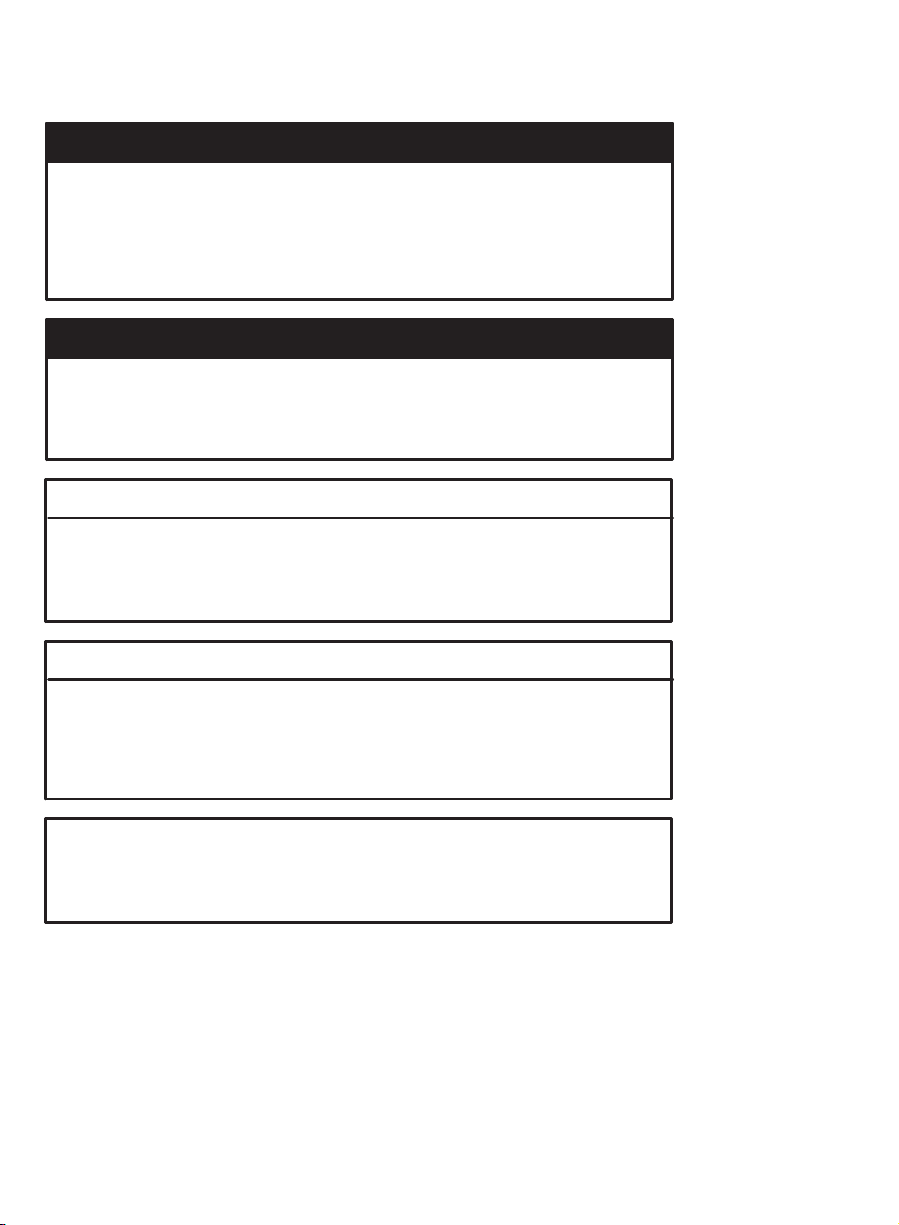
the logic circuitry of modules in the Rack. On the faceplate of the M/N
57C493 Power Supply module are two LED indicators, a terminal
block connector, a keyswitch, a fuse, and a battery backĆup
connector. See figure 2.1.
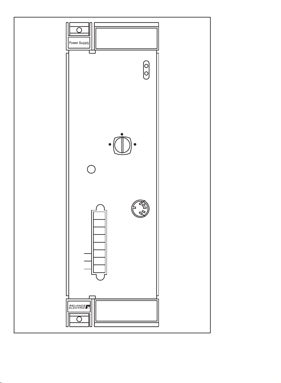
On the faceplate of the M/N 57C494 Power Supply module are two
LED indicators, a terminal block connector, a keyswitch, and a fuse.
See figure 2.2.
2Ć1
Page 10
376W
57C493
PROGRAM
FUSE TYPE
250 V
MDA 15A
MEMORY
PROTECT
POWER
FAULT
SET
UP
BATTERY
BACK UP
2Ć2
GND
L2
120 VAC
L1
Figure 2.1Ć 376W Power Supply Module (M/N 57C493)
Page 11
147W
57C494
POWER
FAULT
PROGRAM
MEMORY
PROTECT
FUSE TYPE
250 V
MDA 5A
SET
UP
L2
120 VAC
L1
Figure 2.2Ć 147W Power Supply Module (M/N 57C494)
2Ć3
Page 12

2.1.1 Power Supply Module LED Indicators
The Power Supply module faceplate contains 2 LEDs. The green LED
labeled POWER" is lit to indicate when incoming AC power is within
the specified ranges. The red LED labeled FAULT" is normally off.
When it is on, it indicates the output voltages are not all above the
low voltage alarm thresholds or the watchdog OK signal is high.
2.1.2 Power Supply Module Terminal Block
The terminal block on the Power Supply faceplate provides the
means to connect the 115 VAC power and a ground wire from the
rack to the module. Note that terminals 1-5 (reading top to bottom)
are not functional.
The green ground wire from the Rack connects to the GND"
terminal on the faceplate of the Power Supply. Terminal L2" is the
connection for the AC neutral input line from the Rack. Terminal L1"
is the connection for the AC hot input line from the Rack. See section
3.2 for more information.
2.1.3 Power Supply Module Battery Connection
(M/N 57C493 only)
The faceplate connection labeled BATTERY BACK UP" provides the
means to connect the Battery BackĆUp (M/NĂ57C492) to the Power
Supply module. Note that the Battery BackĆUp unit is required only
when there is a DCS 5000 Processor module (M/NĂ57C407) or a
Common Memory module (M/NĂ57C413 or 57C413A only) in the
Rack. The Battery BackĆUp unit can save the contents of the
Common Memory and DCS 5000 Processor RAM in the event of a
power failure.
The keyswitch is used to reset the OK" signal on the Battery
BackĆUp. It is necessary to reset this signal if the battery fails or if the
cable is removed. See 2.1.4 and 2.2 for more information.
Note that the M/N 57C494 Power Supply module does not contain a
Battery BackĆup connection. Therefore, the above mentioned
Processor and Common Memory modules cannot be used with the
M/N 57C494 Power Supply.
2.1.4 Power Supply Module Keyswitch
The keyswitch on the faceplate routes TTL signals through the
Multibus backplane to the Processor module(s) to allow lockout of
programming functions for system security. The three positions of the
keyswitch are PROGRAM, MEMORY PROTECT, and SET UP. The
position of the keyswitch indicates the security level of the rack, i.e.,
the kind of ONĆLINE Menu operations that can be performed through
a personal computer communicating with the processors in the rack.
The MEMORY PROTECT position allows only monitoring of variables
and saving of tasks from the rack. SETUP allows the operator to
monitor all variables, modify tunable variables, and save tasks from
the rack. The PROGRAM position allows the operator to perform all
ONĆLINE Menu functions, providing the password for the rack is also
entered. See the appropriate Programming Executive instruction
manual for more information.
2Ć4
Page 13

2.2 Power Supply Module Electrical
Description
When the Power Supply module powersĆup, it executes a soft start,"
gradually increasing its output until it reaches the voltage necessary
for logic operations. At this time, the module generates an initialize
signal.
Should the AC input fall below the lower line voltage limit, the module
will generate a power fail interrupt signal at least three milliseconds
before loss of the regulated DC power to allow for orderly system
shutdown. The holdover time on loss of AC input is 20 milliseconds.
In the event of a power fail interrupt signal, 5 Volt output power is
supplied by the Battery BackĆUp (if installed, M/N 57C493 only) for
maintaining the volatile memory of DCS 5000 Processor modules
and the Common Memory module. When the regulated output power
of the Power Supply module is restored to 4.85 Volts or greater,
power will be supplied by the Power Supply module. Note that
AutoMax Processors have onĆboard battery backĆup and do not
require Battery BackĆUp unless there is a Common Memory module
(M/N 57C413 or 57C413A only) in the rack.
If Battery BackĆUp Voltage ever drops below 3.0 Volts, or the cable
between the Battery BackĆUp and M/N 57C493 Power Supply
module is disconnected with the power off, memory will be lost and
the Processor modules will not function until the Power Supply is
manually reset by turning the keyswitch on the front panel from
MEMORY PROTECT to the PROGRAM position.
2.3 Rack Mechanical Description
The 6Ć, 10Ć, and 16ĆSlot Racks provide the mechanical means for
mounting the indicated number of DCS 5000 and AutoMax modules,
as well as the Power Supply module. All Racks are designed for
panel mounting and include builtĆin high capacity cooling fans, an
AC line filter, a surge protector, and a cable management tray. See
figures 2.3, 2.4, and 2.5.
2Ć5
Page 14
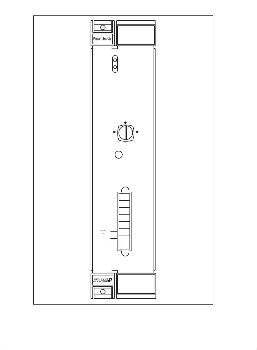
(Nameplate Bracket Removed)
Figure 2.3Ć 6ĆSlot Rack
(Nameplate Bracket Removed)
Figure 2.4Ć 10ĆSlot Rack
2Ć6
Page 15

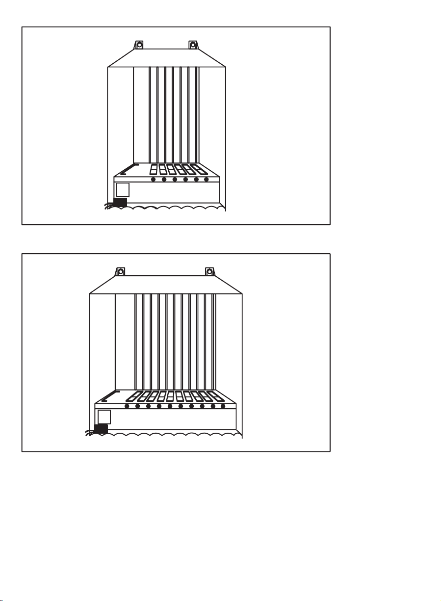
(Nameplate Bracket Removed)
Figure 2.5 Ć 16ĆSlot Rack
Dedicated signal lines on the Multibus backplane require limitations
on slot placement for some types of DCS 5000/AutoMax modules.
See figure 2.6.
Module Slot Position
Module 0 1 2 3 4 5 6 7 8 9 10 11 12 13 14 15
6ĆSlot Rack:
Common
D
Memory
Processor D D D D D
DCS DC Drive
1
All Other D D D D D D
10ĆSlot Rack:
Common
D
Memory
Processor D D D D D
DCS DC Drive
2
D D D D
All Other D D D D D D D D D D
16ĆSlot Rack:
Common
D
Memory
Processor D D D D D
DCS DC Drive
2
D D D D D D D D
All Other D D D D D D D D D D D D D D D D
1
Cannot be used in a 6ĆSlot Rack.
2
Must be grouped together.
Figure 2.6Ć Rack Slot Limitations
2Ć7
Page 16

2.4 Rack Electrical Description
The Multibus backplane of the Rack supports two sets of bus lines
that serve as the electrical connection for all slots in the Rack. The P1
bus, the larger of the two electrical connectors, conforms to the IEEE
Microcomputer System Bus Standard for the P796 bus, compliance
level D16M20I16. This bus is used for communication and control
signals among the different modules in the Rack. The P2 bus, the
smaller of the two backplane electrical connectors, follows a Reliance
pin assignment as permitted by the IEEE P796 standard. The P2 bus
is used for functions such as determining the slot number of the
module. See Appendix C for a description of the pins on the Rack
backplane. See JĆ3649, JĆ3750, or J2Ć3045 for guidelines on using
nonĆReliance modules in the Rack.
The AC line filter on the Rack filters the incoming power signal before
it is transmitted to the Power Supply module. The surge protector
provides power supply protection from power surges. No other
connections to the AC line are permitted between the line filter and
the Power Supply module. See figure 2.7 for a typical input power
signal.
KVA < 50
115 VAC
HOT
115 VAC
NEUTRAL
188
189
RACK
2Ć8
Figure 2.7Ć Typical Input Power Connections
Page 17

3.0 INSTALLATION
This section describes how to install and replace the Power Supply
module and Rack.
DANGER
THE USER IS RESPONSIBLE FOR CONFORMING WITH ALL APPLICABLE
LOCAL, NATIONAL, AND INTERNATIONAL CODES. WIRING PRACTICES,
GROUNDING, DISCONNECTS, AND OVERĆCURRENT PROTECTION ARE OF
PARTICULAR IMPORTANCE. FAILURE TO OBSERVE THIS PRECAUTION
COULD RESULT IN SEVERE BODILY INJURY OR LOSS OF LIFE.
CAUTION: This equipment must be connected to a power source for which it was
designed. Verify that the available poweris 115 volts. Failure to observethis precaution
could result in damage to equipment.
3.1 Wiring
To reduce the possibility of electrical noise interfering with the proper
operation of the control system, exercise care when installing the
wiring between the system and the external devices. For detailed
recommendations refer to IEEE 518.
The external wiring to the modules in the Rack must be carefully
routed to minimize electrical noise and crosstalk between input and
output wiring. Group and bundle wire types by similar electrical
signals, being especially careful to separate lowĆ and highĆlevel
control signals and AC and DC wiring.
If the 115 VAC input signal is subject to severe harmonic distortion,
install a constant voltage transformer on the line.
3.2 Initial Installation
CAUTION:The cabinetor panelon which the rack is mounted must belocatedinanarea
away from or shielded from sources of EMI, such as radar beams and transmission
towers. Failure to observe this precaution couldresult indamage to or destruction of the
equipment.
CAUTION:Air flow around the rackmust be sufficient to dissipate the heatgeneratedby
all of the hardwarein and around the rack. Allow atleast twoinches of clearance on each
side of the rack. Avoid placing large, heatĆgenerating equipment underneath the rack
fans. Additional userĆsupplied fan cooling or air conditioning is required if the ambient
temperature exceeds 60_C. Failure to observethis precaution could result in damage to
or destruction of the equipment.
3Ć1
Page 18

CAUTION: The rack must be located in a clean environment.Do not expose the rack to
dripping water or corrosive atmospheres containing carbon dust, metal particles, or
other contaminants. Failure to observe this precaution could result in damage to or
destruction of the equipment.
Use the following procedure to install the Rack and Power Supply
module. Before you begin, make certain that you have provided
enough space for the Rack, wiring, and terminal strips or other
devices that must be mounted near the Rack. Make certain that the
panel is sturdy enough to support the Rack and all modules that it
will hold. Including connectors attached to module faceplates, a
fullyĆloaded 6ĆSlot Rack weighs approximately 40 lbs. A fullyĆloaded
10ĆSlot Rack weighs between 70 and 80 lbs. A fullyĆloaded 16ĆSlot
Rack weighs between 105Ć115 lbs.
Step 1. Mount the Rack on a panel or cabinet made of heavy
Step 2. Mount the Power Supply module in the Rack following the
gauge steel sturdy enough to hold the Rack, all of the
hardware modules that will go into the Rack, and the
terminal strip/connector assemblies for I/O modules. The
connector end of each terminal strip/connector assembly
is attached to the appropriate module faceplate. The
terminal strip end of each assembly can be mounted on
the panel itself or on lashing bars attached to the panel.
Refer to the instruction manual for each individual module
in your installation for more specific information. Follow the
procedure below to install the Rack.
a) Drill four holes in the panel using the appropriate
mounting pattern in Appendix D.
b) In each hole, screw in one 1 1/4" 20Ćthread Tap titet
bolt, leaving approximately 1/8" to 1/4" of the thread
exposed.
c) Remove the large nameplate bracket (labeled
AutoMax") from the rack by removing the three screws
near the base holding it to the cable guide area.
d) Position the Rack against the panel at a slight angle so
that the bottom is a few inches away from the panel.
Place the top of the Rack against the panel so that the
upper two bolts are visible through the larger part of
the bolt holes at the top of the Rack.
Carefully slide the Rack down so that the bolts are
wedged in the top (smaller) area of the bolt holes,
while at the same time moving the lower portion of the
Rack toward the cabinet or panel onto the lower bolts.
The lower bolts should be firmly wedged against the
upper edge of the lower bolt holes on the Rack.
Tighten all the bolts.
steps below.
a) Take the Power Supply module out of its shipping
container and antiĆstatic bag, being careful not to
touch the connectors on the back of the module.
b) Remove the two keyswitch keys which are taped to the
front of the module. Insert the module into the leftmost
and widest slot in the Rack. Use a screwdriver to attach
3Ć2
Page 19

the module to the Rack. Store the keyswitch keys in a
secure area.
c) Connect the Battery BackĆUp unit, if used. Plug one
end of the Battery BackĆUp cable into the Power
Supply module faceplate connector labeled BATTERY
BACK UP". Plug the other end of the cable into the
Battery BackĆUp unit. Rotate the keyswitch on the front
panel from Memory Protect to the Program position.
Step 3. Mount the terminal strip end of the terminal strip/connector
Step 4. Fasten wiring for the external hardware to the terminal
Step 5. Take the Processor module(s) and other modules out of
Step 6. Attach the connector ends of the terminal strip/connector
Step 7. Wire the Rack following the instructions below.
assemblies for I/O modules on the panel or on lashing
bars. The terminal strips should be mounted to permit
easy access to the screw terminals. Make certain that the
strips are close enough to the Rack so that the connecting
cables will reach between terminal strips and the modules.
Most cables are approximately 60" long.
strips. Make certain that all field wires are securely
attached. Label all terminal strips and field wires to allow
easy reconnection at a later date.
For I/O modules, note carefully that bit numbers and wire
numbers (located on wires between the faceplate
connector and terminal strip) are not the same. Refer to
the installation section of the instruction manuals
describing the I/O modules for more information.
their shipping containers and insert them into the desired
slots. See figure 2.6 for slot restrictions for certain
modules. Use a screwdriver to attach the modules to the
Rack.
assemblies to their mating halves on the appropriate
modules. Use a screwdriver to attach the connectors to
the modules. Use the cable guides at the base of the rack
to keep cables separate.
Note that in most cases both the connectors and their
mating halves are equipped with movable keys". These
keys should be used to prevent the wrong connector from
being plugged into a module in the event that the
connector needs to be removed and then reĆattached
later.
At the time of installation, rotate the keys on the connector
and the mating half on the module to mirror image
positions so that they can be connected together securely.
For all modules equipped with keys, the key on each
successive module in the Rack should be rotated one
position to the right of the key on the preceding module.
CAUTION: Do not connect incoming AC power directly to the power supply module
faceplate. Connect AC power to the correct terminals on therack only.Failuretoobserve
this precaution could result in damage to or destruction of the equipment.
3Ć3
Page 20

a) Ground the cabinet or panel on which the Rack will be
mounted. Make certain that there is an unbroken path
from the cabinet to the plant ground (earth).
b) Ground the rack with a ground wire connected to one
of the protective ground terminals provided on each
side of the rack. The ground wire color and size must
be in accordance with appropriate international and
national standards and codes.
c) Connect incoming AC power to the Rack as follows:
Rack Terminal Label
189 120 VAC
188 120 VAC + (hot)
Cover the incoming wire ends with a Fastont
connector and attach them securely to the appropriate
terminals using a screwdriver.
d) Connect the power and ground wires from the Rack to
the Power Supply module as follows:
Wire Color
black L2 L2
orange L1 L1
green - GND
The wires labeled L2 and L1 should remain twisted
together as much as possible between the Rack and
the Power Supply module.
Step 8. Using a screwdriver, reĆattach the nameplate bracket to
the base of the rack.
Step 9. Turn on power to the system.
THE POWER SUPPLY MODULE OPERATES USING AC INPUT VOLTAGE
CAPABLE OF PRODUCING SEVERE SHOCK. MAKE CERTAIN THAT THE
EXTERNAL AC SUPPLY CIRCUIT IS TURNED OFF BEFORE INSERTING OR
REMOVING THE MODULE OR ANY CONNECTING CABLES. FAILURE TO
OBSERVE THIS PRECAUTION COULD RESULT IN SEVERE BODILY INJURY OR
LOSS OF LIFE.
Wire Label
DANGER
Input
Power Supply
Faceplate Connector
3Ć4
Step 10. Verify the installation by connecting the personal computer
to the port labeled PROGRAMMER/PORT B" on the
leftmost Processor in the Rack and running the ReSource
programming software. Try to read from or write to the
registers on each of the modules in the Rack.
Page 21

WARNING
BE CAREFUL TO INSURE THAT NO UNEXPECTED MACHINE MOTION WILL
RESULT WHEN WRITING TO OUTPUTS. FAILURE TO OBSERVE THIS
PRECAUTION COULD RESULT IN BODILY INJURY.
Refer to the instruction manuals describing other
hardware in the installation for more information.
3.3 Power Supply Module Replacement
Use the following procedure to replace the Power Supply module:
Step 1. Turn off power to the Rack and all connections.
DANGER
THE POWER SUPPLY MODULE OPERATES USING AC INPUT VOLTAGE
CAPABLE OF PRODUCING SEVERE SHOCK. MAKE CERTAIN THAT THE
EXTERNAL AC SUPPLY CIRCUIT IS TURNED OFF BEFORE INSERTING OR
REMOVING THE MODULE OR ANY CONNECTING CABLES. FAILURE TO
OBSERVE THIS PRECAUTION COULD RESULT IN SEVERE BODILY INJURY OR
LOSS OF LIFE.
Step 2. Use a screwdriver to disconnect the terminal strip from the
Step 3. Use a screwdriver to loosen the screws holding the Power
Step 4. Mount the replacement Power Supply module in the Rack
Power Supply module. Do not remove the wires from the
terminal strip. Disconnect the Battery BackĆUp cable, if
used.
Remove the nameplate bracket from the rack by removing
the three screws near the base holding it to the cable
guide area.
Supply module in the Rack and remove the module, being
careful not to touch the connectors on the back. Store the
module in the antiĆstatic bag it came in.
following the steps below:
a) Take the replacement Power Supply module out of its
shipping container and antiĆstatic bag, being careful
not to touch the connectors on the back of the module.
b) Remove the two keys to the keyswitch which are taped
to the front of the module. Store the keyswitch keys in
a secure area. Use a screwdriver to disconnect the
terminal strip from the replacement Power Supply
module.
c) Insert the module into the leftmost and widest slot in
the Rack. Use a screwdriver to attach the module to
the Rack.
d) Use a screwdriver to attach the terminal strip from the
old Power Supply module to the replacement Power
Supply module. Make certain that the connector is
attached correctly by verifying that the wiring and the
terminal labels on the faceplate match as follows:
3Ć5
Page 22

Power Supply
Wire Color
black L2 L2
orange L1 L1
green - GND
e) If you are using the Battery BackĆUp unit, plug one end
of the Battery BackĆUp cable into the Power Supply
module faceplate connector labeled BATTERY BACK
UP". Plug the other end into the Battery BackĆUp unit.
Rotate the keyswitch on the front panel from Memory
Protect to the Program position.
f) Using a screwdriver, reĆattach the nameplate bracket to
the base of the rack.
Step 5. Turn on power to the system.
Step 6. Verify the installation by connecting the personal computer
to the port labeled PROGRAMMER/PORT B" on the
leftmost Processor in the Rack and running the ReSource
programming software. Try to read from or write to the
registers on each of the modules in the Rack.
WARNING
BE CAREFUL TO INSURE THAT NO UNEXPECTED MACHINE MOTION WILL
RESULT WHEN WRITING TO OUTPUTS. FAILURE TO OBSERVE THIS
PRECAUTION COULD RESULT IN BODILY INJURY OR DAMAGE TO EQUIPMENT.
Refer to the instruction manuals describing the specific
hardware in the installation for more information.
Wire Label
Faceplate Connector
3.4 Rack Replacement
Use the following procedure to replace the Rack:
Step 1. Turn off power to the Rack and all connections.
DANGER
THE POWER SUPPLY MODULE OPERATES USING AC INPUT VOLTAGE
CAPABLE OF PRODUCING SEVERE SHOCK. MAKE CERTAIN THAT THE
EXTERNAL AC SUPPLY CIRCUIT IS TURNED OFF BEFORE INSERTING OR
REMOVING THE MODULE OR ANY CONNECTING WIRES. FAILURE TO
OBSERVE THIS PRECAUTION COULD RESULT IN SEVERE BODILY INJURY OR
LOSS OF LIFE.
Step 2. Using a screwdriver, remove the nameplate bracket from
Step 3. Use a screwdriver to loosen the screws holding all
3Ć6
the rack by removing the three screws near the base
holding it to the cable guide area. Loosen all the screws
holding connectors to the modules in the Rack. Remove
the connectors. Disconnect the wires attached to the
terminal strip on the Power Supply module.
modules, including the Power Supply module, in the Rack.
Page 23

Take all of the modules out of the Rack, being careful not
to touch the connectors on the back.
Step 4. Loosen the bolts that hold the rack to panel approximately
Step 5. Position the replacement Rack against the panel at a slight
Step 6. Insert the Power Supply module into the leftmost and
Step 7. If you are using the Battery BackĆUp unit, plug one end of
Step 8. Insert the Processor module(s) and other modules. Use a
Step 9. Use a screwdriver to attach the connectors to their mating
Step 10. Connect 115 VAC power to the Rack following the
1/8"-1/4". Lift the Rack slightly while holding it against the
panel until both top bolts are positioned in the larger bolt
holes and the lower two bolts have cleared the smaller
holes. Pull the Rack away from the panel and set aside.
angle so that the bottom is a few inches away from the
panel. Place the Rack against the panel so that the upper
two bolts are visible through the larger part of the bolt
holes at the top of the Rack.
Carefully slide the Rack down so that the bolts are
wedged in the top (smaller) area of the bolt holes, while at
the same time moving the lower portion of the Rack
toward the cabinet or panel onto the lower bolts. The
lower bolts should be firmly wedged against the upper
edge of the lower bolt holes on the Rack. Tighten all the
bolts.
widest slot in the Rack. Use a screwdriver to attach the
module to the Rack.
the Battery BackĆUp cable into the Power Supply module
faceplate connector labeled BATTERY BACK UP". Plug
the other end into the Battery BackĆUp unit. Rotate the
keyswitch on the front panel from Memory Protect to the
Program postion.
screwdriver to attach the modules to the Rack.
halves on the appropriate modules.
instructions below.
CAUTION: Do not connect incoming AC power directly to the power supply module
faceplate. Connectpowerto thecorrect terminals ontherackonly.Failureto observe this
precaution could result in damage to or destruction of the equipment.
a) Make certain that there is an unbroken path from the
cabinet to the plant ground.
b) Connect incoming AC power to the Rack as follows:
Rack Terminal Label
189 120 VAC
188 120 VAC + (hot)
Cover the incoming wire ends with a Fastont
connector and attach them securely to the appropriate
terminals using a screwdriver.
c) Connect the power and ground wires from the Rack to
the Power Supply module as follows:
Input
3Ć7
Page 24

Power Supply
Wire Color
black L2 L2
orange L1 L1
green - GND
The wires labeled L2 and L1 should remain twisted
together as much as possible between the Rack and
the Power Supply module.
Step 11. Using a screwdriver, reĆattach the nameplate bracket to
the base of the rack.
Step 12. Turn on power to the system.
Step 13. Verify the installation by connecting the personal computer
to the port labeled PROGRAMMER/PORT B" on the
leftmost Processor in the Rack and running the ReSource
programming software. Try to read from or write to the
registers on each of the modules in the Rack.
WARNING
WHEN WRITING TO OUTPUTS, BE CAREFUL TO INSURE THAT NO UNEXPECTED
MACHINE MOTION WILL RESULT. FAILURE TO OBSERVE THIS PRECAUTION
COULD RESULT IN BODILY INJURY OR DAMAGE TO EQUIPMENT.
Refer to the instruction manuals describing the specific
hardware in the installation for more information.
Wire Label
Faceplate Connector
3Ć8
Page 25

4.0 DIAGNOSTICS AND
TROUBLESHOOTING
This section explains how to troubleshoot the Power Supply module
and Rack. Any problems with either the Power Supply module or the
Rack can usually be isolated by observing the condition of the LEDs
on the Power Supply module faceplate. Problems with the Rack
backplane (bus) will result in error codes on the LEDs of Processor
modules in the Rack. See JĆ3650 for more information on
troubleshooting the AutoMax Processor module.
DANGER
THE POWER SUPPLY MODULE OPERATES USING AC INPUT VOLTAGE
CAPABLE OF PRODUCING SEVERE SHOCK. MAKE CERTAIN THAT THE
EXTERNAL AC SUPPLY CIRCUIT IS TURNED OFF BEFORE INSERTING OR
REMOVING THE MODULE OR ANY CONNECTING WIRES. FAILURE TO
OBSERVE THIS PRECAUTION COULD RESULT IN SEVERE BODILY INJURY OR
LOSS OF LIFE.
If the problem cannot be determined using the troubleshooting
instructions below, the hardware is not userĆserviceable.
DANGER
SOME OF THESE STEPS ARE MADE WITH POWER ON. EXERCISE EXTREME
CARE BECAUSE HAZARDOUS VOLTAGE EXISTS. FAILURE TO OBSERVE THIS
PRECAUTION COULD RESULT IN SEVERE BODILY INJURY OR LOSS OF LIFE.
4.1 The POWER LED Is Off
Problem: the POWER LED on the Power Supply module is off. This
LED should always be on when input power is on and the input fuse
is in place and functioning correctly. If the LED is off, the module is
not receiving 120 VAC power. Use the following procedure to isolate
the problem.
Step 1. Using a voltmeter, verify that the Rack is receiving 120 VAC
power.
Step 2. Turn off power to the Rack. Wait until all of the LEDs on the
faceplate of the Power Supply module have gone out.
Verify that the connections at the Rack and the L1 and L2
connections at the Power Supply module are tight.
Step 3. Remove the fuse cap and fuse and, using an Ohm meter,
verify that the fuse is not blown. If the fuse is good,
reĆinsert it and continue with step 4.
If the fuse is blown, verify that, for M/N 57C493, it is a 15A
MDA time delay type fuse. M/N 57C494 should contain a
5A MDA time delay type fuse. A blown fuse indicates that
the Power Supply should be replaced.
Step 4. Turn on power to the Rack. If the problem is not corrected,
replace the Power Supply.
4Ć1
Page 26

4.2 The FAULT LED is On
Problem: the FAULT LED on the Power Supply module is ON. This
LED should always be off when input power is on, the Power Supply
output voltage is within proper limits, and the watchdog alarm
coming from the backplane is not active. The rack must also contain
at least one AutoMax Processor module (or, for a remote rack, a
Remote I/O module). Note that the FAULT LED will be ON if there is
no Processor (or Remote I/O module) in the rack.
Use the following procedure to determine whether the problem is
caused by a malfunctioning Power Supply or by a watchdog alarm.
Step 1. Verify that the Power Supply is securely seated in the rack.
Step 2. If you have more than one Processor in the rack, a
Step 3. Turn off power to the rack. Replace the Processor or
Step 4. If the Power Supply FAULT LED turns ON, the Power
The FAULT LED will come ON if there is not a good
connection to the rack backplane.
watchdog timeout will not be indicated by the Power
Supply FAULT LED. If the Power Supply FAULT LED is ON,
the Power Supply must be replaced.
If the rack contains a single AutoMax Processor or is a
remote rack, check the OK LED on the Processor module
or Remote I/O module. If the OK LED is OFF, it may
indicate a watchdog timeout.
Remote I/O module. Turn on power to the rack.
Supply is malfunctioning. Replace the Power Supply.
4Ć2
Page 27

Appendix A
Technical Specifications
Power Supply Module (M/N 57C493)
Ambient Conditions
D Storage temperature: -40oCĆ85oC
D Operating temperature: 0_CĆ60_C
D Humidity: 5-90% nonĆcondensing
D Altitude: operation from sea level at 60
with linear derating of 1
Dimensions
D Height: 29.8 cm 113/4inches
D Width: 10.2 cm ă4 inches
D Depth: 19.7 cm ă7
D Weight: ă3.8 kg 8
3
/4inches
1
/2lbs
System Power Requirements
D Input voltage: nominal 100/120 VAC, 85Ć132 VAC acceptable
D Current: 6 Amp at 120 VAC
D Frequency: nominal 50/60 Hz, 47Ć63 Hz acceptable range
D Protection: 15 Amp 250 VAC MDA time delay fuse
D Fault current limit: 10,000 Amps
D Maximum source rating: 50KVA
range
DC Output
D +5 VDC at 50 amps
D +/-12 VDC at 4 amps
D +/-15 VDC at 1 amp
D Maximum continuous output power: ă376 Watts
D Holdup time: 20 msec. minimum after loss of AC input
Regulation
D Nominal +5 VDC: -2.5% to +3% regulation
D Nominal +/- 12 VDC: +/-10% regulation
D Nominal +/- 15 VDC: +/- 1% regulation
Efficiency
D 75% minimum at nominal line voltage and full load
Isolation
D 1500 VDC for 1 sec input to output and input to chassis
D 700 VDC for 1 sec output to chassis
Protection
D Overvoltage: +5V 5.6V+/-0.15V
+/-12V 14.4V +/-0.6V
+/-15V 16.5V +/-0.5V
o
C to 10,000 feet (3048 meters)
o
C per 1000 feet above 5000 feet.
AĆ1
Page 28

Technical Specifications
Power Supply Module (M/N 57C494)
Ambient Conditions
D Storage temperature: -40oCĆ85oC
D Operating temperature: 0_CĆ60_C
D Humidity: 5-90% nonĆcondensing
D Altitude: operation from sea level at 60
with linear derating of 1
Dimensions
D Height: 29.8 cm 113/4inches
D Width: 7.1 cm ă2
D Depth: 19.7 cm ă7
D Weight: ă2.6 kg 5
13
/16inches
3
/4inches
3
/4lbs
System Power Requirements
D Input voltage: nominal 100/120 VAC, 85Ć132 VAC acceptable
D Current: 2.6 Amp at 120 VAC
D Frequency: nominal 50/60 Hz, 47Ć63 Hz acceptable range
D Protection: 5 Amp 250 VAC MDA time delay fuse
D Fault current limit: 10,000 Amps
D Maximum source rating: 50KVA
range
DC Output
D +5 VDC at 20 amps
D +/-12 VDC at 1 amp
D +/-15 VDC at 0.75 amp
D Maximum continuous output power: ă147 Watts
D +5 VDC output holdup time: 3 msec. minimum after loss of AC input at
D Input line loss: capable of a 1 cycle 60 Hz line loss at nominal input
line voltage
full load and minimum input line voltage
Regulation
D Nominal +5 VDC: -2.5% to +3% regulation
D Nominal +/- 12 VDC: +/-10% regulation
D Nominal +/- 15 VDC: +/- 1% regulation
Efficiency
D 65% minimum at nominal line voltage and full load
Isolation
D 1500 VDC input to output
D 700 VDC output to chassis
Protection
D Overvoltage: +5V 5.6V+/-0.15V
+/-12V 14.4V +/-0.6V
+/-15V 16.5V +/-0.5V
o
C to 10,000 feet (3048 meters)
o
C per 1000 feet above 5000 feet.
AĆ2
Page 29

Technical Specifications
16ĆSlot, 10ĆSlot and 6ĆSlot Rack
Ambient Conditions
D Storage temperature: -55oCĆ85oC
D Operating temperature: 0
D Humidity: 5Ć90% nonĆcondensing
Rack Dimensions
M/NĂ57C331 16ĆSlot Rack
D Height: 48.6 cm 191/8inches
D Width: 62.4 cm 24
D Depth: 31.1 cm 12
D Approximate Weight: 50 kg fully loaded 110 lbs
M/NĂ57C332 10ĆSlot Rack
D Height: 48.6 cm 19
D Width: 43.3 cm 171/16inches
D Depth: 31.1 cm 12
D Approximate Weight: 34ăkg fully loaded 75 lbs
M/NĂ57C334 6ĆSlot Rack
D Height: 48.6 cm 19
D Width: 27.5 cm 103/16inches
D Depth: 31.1 cm 121/4inches
D Approximate Weight: 18ăkg fully loaded 39.5 lbs
Bus Specifications
D Type: Intel Multibust
D P1 bus connector: IEEE standard P796 bus
D P2 bus connector: IEEE standard P796 modified bus
AC Line Filter:
D 10 Amp (M/N 57C331 and M/N 57C332)
D 6 Amp (M/N 57C334)
D 120/250 VAC
D 50/60 Hz
Fans
D Two (2) per Rack (M/N 57C331 and M/N 57C332)
D One (1) per Rack (M/N 57C334)
D Nominal power dissipation: 14 Watts each
o
CĆ60oC
9
/16inches
1
/4inches
1
/8inches
1
/4inches
1
/8inches
AĆ3
Page 30

Page 31

Appendix B
External Connections
Input Power to Rack
(M/N 57C331, 57C332, and 57C334)
Terminal Label Input
189 AC neutral
188 AC hot
GND Rack/earth ground
Rack (M/N 57C331 and 57C332)
to Power Supply Module (M/N 57C493)
Power Supply
Wire Color Wire Label
black L2 L2
orange L1 L1
green - GND
Rack (M/N 57C331, 57C332, and 57C334)
to Power Supply Module (M/N 57C494)
Faceplate Connector
Power Supply
Wire Color Wire Label
black L2 L2
orange L1 L1
green - GND
Faceplate Connector
BĆ1
Page 32

Page 33

Appendix C
Rack Backplane
P1 Bus
Component Side
1
Pin
Power
Supplies13
Bus
Controls1315
Bus
Controls
and
Addresses
Parallel
Interrupts
Requests
Address 43
Data 59
Power
Supplies7577 NC
NC: No connection
MOD: Modified definition of Multibus specification
NU: No usage in system; driven per Multibus specification
5
7
9NC
11
17
19
21
23
25
27
29
31
33 NC
35 MOD
37 NC
39
41
45
47
49
51
53
55
57
61
63
65
67
69
71
73
79
81
83
85
Mnemonic Description
GND
+5V
+5V
+12V
-5V
GND
BCLK
BPRN/
BUSY/
MRDC/
IORC/
XACK/
LOCK/
BHEN/
CBRQ/
CCLK/
INTA/
INT6/
INT4/
INT2/
INT0/
ADRE/
ADRC/
ADRA/
ADR8/
ADR6/
ADR4/
ADR2/
ADR0/
DATE/
DATC/
DATA/
DAT8/
DAT6/
DAT4/
DAT2/
DAT0/
GND
-12V
+5V
+5V
GND
Signal Ground
+5 VDC
+5 VDC
+12 VDC
-5 VDC
Signal Ground
Bus Clock
Bus Priority In
Bus Busy
Memory Read Command
I/O Read Command
Transfer Acknowledge
Lock
Byte Hi Enable
Common Bus Request
Common Clock
Interrupt Acknowledge
CPU Communication Interrupt
General Purpose Interrupt
General Purpose Interrupt
General Purpose Interrupt
Address Bus
Data Bus
Signal Ground
Reserved
-12V
+5 VDC
+5 VDC
Signal Ground
CĆ1
Page 34

Rack Backplane (Cont.)
P1 Bus (Cont.)
Solder Side
1
Pin
Power
Supplies24
Bus
Controls1416
Bus
Controls
and
Addresses
Parallel
Interrupts
Requests
Address 44
Data 60
Power
Supplies7678 NC
NC: No connection
MOD: Modified definition of Multibus specification
NU: No usage in system; driven per Multibus specification
6
8
10 NC
12
18
20
22
24 MOD
26 MOD
28
30
32
34
36 MOD
38 NC
40
42
46
48
50
52
54
56
58
62
64
66
68
70
72
74
80
82
84
86
Mnemonic Description
GND
+5V
+5V
+12V
-5V
GND
INIT/
BPRO/
BREQ/
MWTC/
IOWC/
PRIV/
MMUMAP
AD10/
AD11/
AD12/
AD13/
INT7/
INT5/
INT3/
INT1/
ADRF/
ADRD/
ADRB/
ADR9/
ADR7/
ADR5/
ADR3/
ADR1/
DATF/
DATD/
DATB/
DAT9/
DAT7/
DAT5/
DAT3/
DAT1/
GND
-12V
+5V
+5V
GND
Signal Ground
+5 VDC
+5 VDC
+12 VDC
-5 VDC
Signal Ground
Initialize
Bus Priority Out
Bus Request
Memory Write Commmand
I/O Write Command
Privilege
MMU Map Select
Address Bus
Address Bus
Address Bus
Address Bus
System WDOG Interrupt
General Purpose Interrupt
General Purpose Interrupt
General Purpose Interrupt
Address Bus
Data Bus
Signal Ground
Reserved
-12V
+5 VDC
+5 VDC
Signal Ground
CĆ2
Page 35

Rack Backplane (Cont.)
P2 Bus
Component Side
Pin Mnemonic Description
1
3
5
7
9
11
13
15
17
19
21
23
25
27
29
31
33
35
37
39
41
43
45
47
49
51
53
55
57
59
AGND
5VB
IDA0/
DB
IDA1/
DB
DB
DB
PFSN/
PFIN/
AGND
A +15V
A -15V
DB DPR0/
DB APR0/
DB APR2/
DB
KEY0/
KEY1/
WDOK/
MPOSO
MPOS2/
MPOS4/
MPOS6/
MPOS8/
MPOSA/
MPOSC/
MPOSE/
MDFLT/
MVAGND
Analog Ground
+5V Battery
Address ID #0
Dedicated High Speed Bus
Address ID #1
Dedicated High Speed Bus
Dedicated High Speed Bus
Dedicated High Speed Bus
Power Fail Sense
Power Fail Interrupt
Analog Ground
Analog +5 VDC
Analog +5 VDC
Data Parity 0
ADDR Parity 0
ADDR Parity 2
Dedicated High Speed Bus
Key Lock Position 0
Key Lock Position 1
Watchdog OK
Dedicated High Speed Bus
Dedicated High Speed Bus
Dedicated High Speed Bus
Dedicated High Speed Bus
Dedicated High Speed Bus
Dedicated High Speed Bus
Dedicated High Speed Bus
Dedicated High Speed Bus
Dedicated High Speed Bus
Dedicated High Speed Bus
CĆ3
Page 36

Rack Backplane (Cont.)
P2 Bus (Cont.)
Solder Side
Pin Mnemonic Description
2
4
6
8
10
12
14
16
18
20
22
24
26
28
30
32
34
36
38
40
42
44
46
48
50
52
54
56
58
60
AGND
5VB
DBR
DBR
IDA2/
DB
IDA3/
DBR
DBR
MPRO/
AGND
A +15V
A -15V
DPR1/
APR1/
PREN/
DIAG/
BD RST/
DB
DB
MPOS1
MPOS3/
MPOS5/
MPOS7/
MPOS9/
MPOSB/
MPOSD/
MPOSF/
MVAREF
MVAGND
Analog Ground
+5V Battery
Dedicated High Speed Bus
Dedicated High Speed Bus
Address ID #2
Dedicated High Speed Bus
Address ID #3
Dedicated High Speed Bus
Dedicated High Speed Bus
Memory Protect
Analog Ground
Analog +15 VDC
Analog -15 VDC
Data Parity 1
ADDR Parity 1
Parity Enable
Diagnostic Loop
Board Reset
Dedicated High Speed Bus
Dedicated High Speed Bus
Dedicated High Speed Bus
Dedicated High Speed Bus
Dedicated High Speed Bus
Dedicated High Speed Bus
Dedicated High Speed Bus
Dedicated High Speed Bus
Dedicated High Speed Bus
Dedicated High Speed Bus
Dedicated High Speed Bus
Dedicated High Speed Bus
CĆ4
Page 37

183/8"
183/8"
Appendix D
Rack Mounting Pattern
16ĆSlot Rack
5
/16"
23
10ĆSlot Rack
13
15
/16"
6ĆSlot Rack
9
9
/16"
183/8"
Dimensions shown are between mounting hole centers.
Diameter of mounting holes: .312"
DĆ1
Page 38

Page 39

Appendix E
Power Requirements of AutoMax Modules
Note: Values are in amps.
Module
M/N 57C400 115VAC/DC Input 0.425 0 0 0 0
B/M 57401Ć1 Drive Digital I/O 0.375 0.1 0.015 0 0
M/N 57C402 24-115VAC/DC
M/N 57C403 115V High Output 1.2 0 0 0 0
M/N 57C404 Network
B/M 57405 Drive Analog I/O 1.2 0.1 0.1 0.15 0.15
M/N 57C409 Analog Input 3.05 0 0 0 0
M/N 57C410 Analog Output 2.75 0.055 0.005 0 0
M/N 57C411 Resolver Input 1.7 0.095 0.095 0 0
M/N 57C413 Common Memory 1.05 0 0 0 0
M/N 57C414 Modbus Interface 2.5 0.053 0.0075 0
M/N 57C415 24VAC/DC Input 0.625 0 0 0 0
M/N 57C416 Remote I/O
M/N 57C417 AutoMate Interface 2.5 0.053 0.0075 0
M/N 57C418 A-B Interface 2.5 0.053 0.0075 0
M/N 57C419 5-24VDC Input 0.7 0 0 0 0
M/N 57C420 5-24VDC Output 0.85 0 0 0 0
M/N 57C421 Pulsetach Input 0.9 0 0 0 0
M/N 57C422 2-Axis Servo 1.6 0 0 0 0
M/N 57C423 Common Memory 1.05 0 0 0 0
M/N 57C428 Toledo Scale
M/N 57C429 AutoMax R-Net
M/N 57C430 AutoMax Processor 3.0 0.1 0.1 0 0
M/N 57C431 AutoMax Processor 3.0 0.1 0.1 0 0
M/N 57C435 AutoMax Processor 3.0 0.1 0.1 0 0
M/N 57C440 Ethernet Interface 5.0 0.5 0.1 0 0
Description +5V +12V -12V +15V -15V
0.525 0.045 0.045 0 0
Output
2.5 0.053 0.0075 0 0
Communication
2.5 0.053 0.0075 0
Communications
2.4 0.053 0.008 0 0
Interface
2.5 0.03 0 0 0
Processor
EĆ1
Page 40

Power Requirements of AutoMax Modules
(Cont.)
Note: Values are in amps.
Module
M/N 57C441 Modbus Plus
M/N 57C442 Data Highway Plus
B/M 57552 Universal Drive
M/N 61C500 115VAC Input 1.2 0 0 0 0
M/N 61C515 24VAC/DC Input 1.2 0 0 0 0
M/N 61C540 Current Input 1.5 0.03 0 0 0
M/N 61C542 Voltage Input 1.5 0.03 0 0 0
M/N 61C544 RTD 1.5 0.03 0 0 0
M/N 61C605 8ĆCh.
M/N 61C613 16ĆChannel Analog
Description +5V +12V -12V +15V -15V
0.6 0 0 0 0
Interface
0.65 0 0 0 0
Interface
1.7 0 0 0.1 0.071
Controller
1.6 0 0 0 0
Thermocouple Input
1.25 0 0 0 0
Input
EĆ2
Page 41

Page 42

Page 43

Page 44

For additional information
1 Allen-Bradley Drive
Mayfield Heights, Ohio 44124 USA
Tel: +1 440 646-3434
http://www.rockwellautomation.com/support
Publication J2-3008-4 - September 1996
Copyright © 2011 Rockwell Automation, Inc. All rights reserved. Printed in U.S.A.
 Loading...