

Page 1
DriveLogix™ 5730
Controller
for PowerFlex® 700S Drives
with Phase II Control
Firmware Version
15.04
User Manual
Page 2
Important User Information
Solid state equipment has operational characteristics differing from those of
electromechanical equipment. Safety Guidelines for the Application, Installation
and Maintenance of Solid State Controls (Publication SGI-1.1 available from your
local Rockwell Automation sales office or online at http://
www.rockwellautomation.com/literature) describes some important differences
between solid state equipment and hard-wired electromechanical devices. Because
of this difference, and also because of the wide variety of uses for solid state
equipment, all persons responsible for applying this equipment must satisfy
themselves that each intended application of this equipment is acceptable.
In no event will Rockwell Automation, Inc. be responsible or liable for indirect or
consequential damages resulting from the use or application of this equipment.
The examples and diagrams in this manual are included solely for illustrative
purposes. Because of the many variables and requirements associated with any
particular installation, Rockwell Automation, Inc. cannot assume responsibility or
liability for actual use based on the examples and diagrams.
No patent liability is assumed by Rockwell Automation, Inc. with respect to use of
information, circuits, equipment, or software described in this manual.
Reproduction of the contents of this manual, in whole or in part, without written
permission of Rockwell Automation, Inc. is prohibited.
Throughout this manual, when necessary we use notes to make you aware of safety
considerations.
WARNING: Identifies information about practices or
circumstances that can cause an explosion in a hazardous
!
environment, which may lead to personal injury or death, property
damage, or economic loss.
Important: Identifies information that is critical for successful application
and understanding of the product.
ATTENTION: Identifies information about practices or
circumstances that can lead to personal injury or death, property
!
damage, or economic loss. Attentions help you:
• identify a hazard
• avoid the hazard
• recognize the consequences
Shock Hazard labels may be located on or inside the equipment
(e.g., drive or motor) to alert people that dangerous voltage may
be present.
Burn Hazard labels may be located on or inside the equipment
(e.g., drive or motor) to alert people that surfaces may be at
dangerous temperatures.
PowerFlex is a registered trademark of Rockwell Automation, Inc.
DriveExplorer, DriveExecutive, and SCANport are trademarks of Rockwell Automation, Inc.
PLC is a registered trademark of Rockwell Automation, Inc.
Page 3

Summary of Changes
Manual Updates
This information summarizes the changes to the DriveLogix5730 Controller
for PowerFlex 700S Drives with Phase II Control, publication 20D-UM003,
since the July 2004 release.
Change See Page...
Added information for contacting Technical Support and updated Controller Firmware
Revision information
Updated information and example for specifying task priorities 1-7
Updated information on controller fault response settings 3-2, 3-6, 3-8,
Updated the System Requirements for configuring DriveLogix Motion 4-1
Updated the Coarse Update Period setting from 4ms to 2ms 4-9
Updated the tables for parameter links and parameter settings for configuring
DriveLogix Motion
Updated the Communicating with Devices on an EtherNet/IP Link procedures to reflect
the support of duplicate IP address detection.
Added information regarding updated MSG packet size. 6-19
Added information regarding updated MSG packet size. 7-9
Added a new Appendix for application restrictions C-1
Preface-2
and 3-12
4-18 and
4-19
6-4
Page 4

soc-2
Page 5

Table of Contents
Important User Information . . . . . . . . . . . . . . . . . . . . . . . . . . . . . . . . . . . . . . . . . . . . . . . 1-2
Summary of
Changes
Preface Overview
Chapter 1 What is DriveLogix5730?
Chapter 2 Placing and Configuring the Drive
Manual Updates . . . . . . . . . . . . . . . . . . . . . . . . . . . . . . . . . . . . . . . . . . . . . . . . . . . . . . . . . i-1
Who Should Use This Manual . . . . . . . . . . . . . . . . . . . . . . . . . . . . . . . . . . . . . . . . . . . . . P-1
Purpose of this Manual . . . . . . . . . . . . . . . . . . . . . . . . . . . . . . . . . . . . . . . . . . . . . . . . . . . P-1
Related Documentation. . . . . . . . . . . . . . . . . . . . . . . . . . . . . . . . . . . . . . . . . . . . . . . . . . . P-2
Contacting Tech Support. . . . . . . . . . . . . . . . . . . . . . . . . . . . . . . . . . . . . . . . . . . . . . . . . . P-2
Controller Firmware Revision. . . . . . . . . . . . . . . . . . . . . . . . . . . . . . . . . . . . . . . . . . . . . . P-3
General Precautions . . . . . . . . . . . . . . . . . . . . . . . . . . . . . . . . . . . . . . . . . . . . . . . . . . . . . P-3
Loading Controller Firmware . . . . . . . . . . . . . . . . . . . . . . . . . . . . . . . . . . . . . . . . . . . . . . 1-2
Using CompactFlash . . . . . . . . . . . . . . . . . . . . . . . . . . . . . . . . . . . . . . . . . . . . . . . . . . . . . 1-5
Developing Programs . . . . . . . . . . . . . . . . . . . . . . . . . . . . . . . . . . . . . . . . . . . . . . . . . . . . 1-6
Selecting a System Overhead Percentage . . . . . . . . . . . . . . . . . . . . . . . . . . . . . . . . . . . . . 1-9
Understanding the Virtual Backplane . . . . . . . . . . . . . . . . . . . . . . . . . . . . . . . . . . . . . . . 1-12
De-energizing the Drive to Connect or Disconnect a Cable . . . . . . . . . . . . . . . . . . . . . . . 2-1
Understanding the Interface to the Drive . . . . . . . . . . . . . . . . . . . . . . . . . . . . . . . . . . . . . 2-1
Determining When the Controller Updates the Drive. . . . . . . . . . . . . . . . . . . . . . . . . . . . 2-2
Placing and Configuring the Drive . . . . . . . . . . . . . . . . . . . . . . . . . . . . . . . . . . . . . . . . . . 2-3
Inhibiting the Drive Connection . . . . . . . . . . . . . . . . . . . . . . . . . . . . . . . . . . . . . . . . . . . 2-11
Using DriveExecutive Lite . . . . . . . . . . . . . . . . . . . . . . . . . . . . . . . . . . . . . . . . . . . . . . . 2-12
Accessing Drive Data . . . . . . . . . . . . . . . . . . . . . . . . . . . . . . . . . . . . . . . . . . . . . . . . . . . 2-21
Monitoring Drive Data . . . . . . . . . . . . . . . . . . . . . . . . . . . . . . . . . . . . . . . . . . . . . . . . . . 2-21
Configuring the Controller’s Response to a Connection Failure . . . . . . . . . . . . . . . . . . 2-22
Recommended Programming Techniques. . . . . . . . . . . . . . . . . . . . . . . . . . . . . . . . . . . . 2-25
Chapter 3 Placing and Configuring Local I/O
De-energizing the Drive to Connect or Disconnect a Cable . . . . . . . . . . . . . . . . . . . . . . . 3-1
Understanding How the DriveLogix5730 Supports
I/O . . . . . . . . . . . . . . . . . . . . . . . . . . . . . . . . . . . . . . . . . . . . . . . . . . . . . . . . . . . . . . . . . . . 3-1
Placing Local I/O Modules . . . . . . . . . . . . . . . . . . . . . . . . . . . . . . . . . . . . . . . . . . . . . . . . 3-2
Validating I/O Layout . . . . . . . . . . . . . . . . . . . . . . . . . . . . . . . . . . . . . . . . . . . . . . . . . . . . 3-3
Estimating RPI . . . . . . . . . . . . . . . . . . . . . . . . . . . . . . . . . . . . . . . . . . . . . . . . . . . . . . . . . 3-4
Determining When the Controller Updates I/O . . . . . . . . . . . . . . . . . . . . . . . . . . . . . . . . 3-4
Configuring the CompactBus . . . . . . . . . . . . . . . . . . . . . . . . . . . . . . . . . . . . . . . . . . . . . . 3-5
Configuring Local I/O Modules . . . . . . . . . . . . . . . . . . . . . . . . . . . . . . . . . . . . . . . . . . . . 3-7
Accessing I/O Data . . . . . . . . . . . . . . . . . . . . . . . . . . . . . . . . . . . . . . . . . . . . . . . . . . . . . 3-12
Direct Connections for I/O Modules. . . . . . . . . . . . . . . . . . . . . . . . . . . . . . . . . . . . . . . . 3-14
Monitoring I/O Modules . . . . . . . . . . . . . . . . . . . . . . . . . . . . . . . . . . . . . . . . . . . . . . . . . 3-15
Configuring I/O Modules Using the Generic 1769-MODULE . . . . . . . . . . . . . . . . . . . 3-17
Page 6

ii
Chapter 4 Configuring DriveLogix Motion
De-energizing the Drive to Connect or Disconnect a Cable . . . . . . . . . . . . . . . . . . . . . . . 4-1
About this Chapter. . . . . . . . . . . . . . . . . . . . . . . . . . . . . . . . . . . . . . . . . . . . . . . . . . . . . . . 4-1
System Requirements . . . . . . . . . . . . . . . . . . . . . . . . . . . . . . . . . . . . . . . . . . . . . . . . . . . . 4-1
Programming the Controller . . . . . . . . . . . . . . . . . . . . . . . . . . . . . . . . . . . . . . . . . . . . . . . 4-2
Launching DriveExecutive from RSLogix . . . . . . . . . . . . . . . . . . . . . . . . . . . . . . . . . . . 4-14
Configuring the Drive with DriveExecutive Software. . . . . . . . . . . . . . . . . . . . . . . . . . . 4-16
Downloading the Settings and Links to the Drive. . . . . . . . . . . . . . . . . . . . . . . . . . . . . . 4-20
Additional Testing and Programming is Necessary. . . . . . . . . . . . . . . . . . . . . . . . . . . . . 4-20
Supported Motion Commands. . . . . . . . . . . . . . . . . . . . . . . . . . . . . . . . . . . . . . . . . . . . . 4-21
Chapter 5 Communicating with Devices on a Serial Link
De-energizing the Drive to Connect or Disconnect a Cable . . . . . . . . . . . . . . . . . . . . . . . 5-1
Configuring Your System for a Serial Link. . . . . . . . . . . . . . . . . . . . . . . . . . . . . . . . . . . . 5-1
Example 1: Workstation Directly Connected to a DriveLogix Controller. . . . . . . . . . . . . 5-6
Example 2: Workstation Remotely Connected to a DriveLogix Controller . . . . . . . . . . . 5-7
Example 3: DriveLogix Controller to a Bar Code Reader. . . . . . . . . . . . . . . . . . . . . . . . 5-10
Chapter 6 Communicating with Devices on an EtherNet/IP Link
De-energizing the Drive to Connect or Disconnect a Cable . . . . . . . . . . . . . . . . . . . . . . . 6-1
Communicating Through the Embedded EtherNet/IP Option. . . . . . . . . . . . . . . . . . . . . . 6-2
Controller Connections Over EtherNet/IP. . . . . . . . . . . . . . . . . . . . . . . . . . . . . . . . . . . . 6-11
Configuring Distributed I/O. . . . . . . . . . . . . . . . . . . . . . . . . . . . . . . . . . . . . . . . . . . . . . . 6-12
Adding a Remote Controller . . . . . . . . . . . . . . . . . . . . . . . . . . . . . . . . . . . . . . . . . . . . . . 6-15
Producing and Consuming Data . . . . . . . . . . . . . . . . . . . . . . . . . . . . . . . . . . . . . . . . . . . 6-15
Using a MSG Instruction to Send an Email. . . . . . . . . . . . . . . . . . . . . . . . . . . . . . . . . . . 6-24
Example 1: DriveLogix5730 Controller and
Distributed I/O . . . . . . . . . . . . . . . . . . . . . . . . . . . . . . . . . . . . . . . . . . . . . . . . . . . . . . . . . 6-31
Example 2: Controller to Controller . . . . . . . . . . . . . . . . . . . . . . . . . . . . . . . . . . . . . . . . 6-32
Chapter 7 Communicating with Devices on a ControlNet Link
De-energizing the Drive to Connect or Disconnect a Cable . . . . . . . . . . . . . . . . . . . . . . . 7-1
Configuring Your System for a ControlNet Link . . . . . . . . . . . . . . . . . . . . . . . . . . . . . . . 7-1
Configuring Distributed I/O. . . . . . . . . . . . . . . . . . . . . . . . . . . . . . . . . . . . . . . . . . . . . . . . 7-4
Scheduling the ControlNet Network . . . . . . . . . . . . . . . . . . . . . . . . . . . . . . . . . . . . . . . . . 7-7
Sending Messages . . . . . . . . . . . . . . . . . . . . . . . . . . . . . . . . . . . . . . . . . . . . . . . . . . . . . . . 7-9
Producing and Consuming Data . . . . . . . . . . . . . . . . . . . . . . . . . . . . . . . . . . . . . . . . . . . 7-14
Chapter 8 Communicating with Devices on a DeviceNet Link
Guidelines for Configuring Connections. . . . . . . . . . . . . . . . . . . . . . . . . . . . . . . . . . . . . 7-17
Example 1: DriveLogix Controller and Remote I/O . . . . . . . . . . . . . . . . . . . . . . . . . . . . 7-18
Example 2: DriveLogix5730 Controller to DriveLogix5730 Controller . . . . . . . . . . . . . 7-19
Example 3: DriveLogix Controller to Other Devices . . . . . . . . . . . . . . . . . . . . . . . . . . . 7-22
De-energizing the Drive to Connect or Disconnect a Cable . . . . . . . . . . . . . . . . . . . . . . . 8-1
Example: Controlling I/O Over DeviceNet . . . . . . . . . . . . . . . . . . . . . . . . . . . . . . . . . . . . 8-2
Page 7

Chapter 9 Communicating with Devices on a DH485 Link
De-energizing the Drive to Connect or Disconnect a Cable . . . . . . . . . . . . . . . . . . . . . . . 9-1
Understanding How the DriveLogix5730 Controller Supports DH485 Communications 9-1
Configuring Your System for a DH-485 Link. . . . . . . . . . . . . . . . . . . . . . . . . . . . . . . . . . 9-2
Planning a DH-485 Network. . . . . . . . . . . . . . . . . . . . . . . . . . . . . . . . . . . . . . . . . . . . . . . 9-4
Installing a DH-485 Network . . . . . . . . . . . . . . . . . . . . . . . . . . . . . . . . . . . . . . . . . . . . . . 9-6
Browsing a DH-485 Network Remotely. . . . . . . . . . . . . . . . . . . . . . . . . . . . . . . . . . . . . . 9-9
Appendix A DriveLogix5730 Controller Specifications
DriveLogix5730 Controller Specifications . . . . . . . . . . . . . . . . . . . . . . . . . . . . . . . . . . . . A-1
DriveLogix5730 Environmental Specifications . . . . . . . . . . . . . . . . . . . . . . . . . . . . . . . . A-1
DriveLogix5730 Certifications . . . . . . . . . . . . . . . . . . . . . . . . . . . . . . . . . . . . . . . . . . . . . A-2
Real-Time Clock Accuracy . . . . . . . . . . . . . . . . . . . . . . . . . . . . . . . . . . . . . . . . . . . . . . . . A-2
Controller LEDs . . . . . . . . . . . . . . . . . . . . . . . . . . . . . . . . . . . . . . . . . . . . . . . . . . . . . . . . A-3
Embedded EtherNet/IP Option LEDs . . . . . . . . . . . . . . . . . . . . . . . . . . . . . . . . . . . . . . . . A-6
Battery Life . . . . . . . . . . . . . . . . . . . . . . . . . . . . . . . . . . . . . . . . . . . . . . . . . . . . . . . . . . . . A-8
Appendix B Access Procedures
Removing Power from Drive and Compact I/O . . . . . . . . . . . . . . . . . . . . . . . . . . . . . . . . B-1
Opening Door Over Power Structure and Main Control Board . . . . . . . . . . . . . . . . . . . . B-2
Removing the Control Cassette from Frame 1-6 Size Drives. . . . . . . . . . . . . . . . . . . . . . B-2
Removing the Outside Covers. . . . . . . . . . . . . . . . . . . . . . . . . . . . . . . . . . . . . . . . . . . . . . B-3
Removing the Inside Cover. . . . . . . . . . . . . . . . . . . . . . . . . . . . . . . . . . . . . . . . . . . . . . . . B-3
Connecting the Battery . . . . . . . . . . . . . . . . . . . . . . . . . . . . . . . . . . . . . . . . . . . . . . . . . . . B-4
Replacing the Battery . . . . . . . . . . . . . . . . . . . . . . . . . . . . . . . . . . . . . . . . . . . . . . . . . . . . B-5
Installing the Embedded EtherNet/IP Option Board. . . . . . . . . . . . . . . . . . . . . . . . . . . . . B-7
Installing the DriveLogix5730 Expansion Board . . . . . . . . . . . . . . . . . . . . . . . . . . . . . . . B-7
Installing the Compact I/O Cable . . . . . . . . . . . . . . . . . . . . . . . . . . . . . . . . . . . . . . . . . . . B-8
Installing the Communications Daughtercard. . . . . . . . . . . . . . . . . . . . . . . . . . . . . . . . . . B-9
iii
Appendix C Application Restrictions
Additional Memory Requirements . . . . . . . . . . . . . . . . . . . . . . . . . . . . . . . . . . . . . . . . . . C-1
Restrictions . . . . . . . . . . . . . . . . . . . . . . . . . . . . . . . . . . . . . . . . . . . . . . . . . . . . . . . . . . . . C-1
Hold Last State and User-Defined Safe State Not Supported. . . . . . . . . . . . . . . . . . . . . . C-3
Index
Page 8

iv
Page 9

Overview
Preface
Who Should Use This Manual
Purpose of this Manual
This manual is intended for qualified personnel. You must be able to
program and operate Adjustable Frequency AC Drive devices and
programmable controllers.
This manual guides the development of projects for DriveLogix controllers.
It provides procedures on how to establish communications:
• with the following networks
– ControlNet
– DeviceNet
– EtherNet/IP
– serial
• with the following devices
– PowerFlex® 700S drive
– controllers
– I/O
– workstations
– PanelView terminals
Page 10

p-2 Overview
Related Documentation
If you are: Use this publication:
a new user of a Logix5000 controller
This quick start provides a visual, step-by-step overview of the basic steps
you need to complete to get your controller configured and running.
an experienced user of Logix5000 controllers
This system reference provides a high-level listing of configuration
information, controller features, and instructions (ladder relay, function
block diagram, and structured text).
any user of a Logix5000 controller
This common procedures manual explains the common features and
functions of all Logix5000 controllers.
For Read this document Document number
Information on the DriveLogix Instruction Set Logix5000 Controllers General Instruction Set Reference
Information on function block programming Logix controllers. Logix5000 Controllers Process Control/Drives Instruction
Execution times and memory use for instructions Logix5000 Controllers Execution Time and Memory Use
Information on selecting CompactLogix and Compact I/O
components and modules
Information on installing, configuring, and using Compact
Analog I/O modules
Information on installing, configuring and using PowerFlex
700S drives
Information on the DriveLogix Motion Control Instruction Set Logix Controller Motion Instruction Set 1756-RM007…
Information on installing an ControlNet communications
daughtercard (Coax)
Information on installing an ControlNet communications
daughtercard (Fiber)
Information on installing an EtherNet/IP communications
daughtercard
Information on installing an DeviceNet communications
daughtercard
Information on installing 1769-SDN DeviceNet Scanner
Module
Information on using 1769-SDN DeviceNet Scanner Module Compact I/O 1769-SDN DeviceNet Scanner Module 1769-UM009…
Information on converting from Phase I PowerFlex 700S and
DriveLogix5720 to Phase II PowerFlex 700S and
DriveLogix5730
Information on the basic installation of PowerFlex 700S drives
and DriveLogix5730 controllers
Allen-Bradley publications are available on the internet at
www.rockwellautomation.com/literature.
These core documents address the Logix5000 family of controllers:
Logix5000 Controllers Quick Start
publication 1756-QS001
Logix5000 Controllers System Reference
publication 1756-QR107
Logix5000 Controllers Common Procedures
publication 1756-PM001
DriveLogix-specific information is also available:
1756-RM003…
Manual
1756-RM006…
Set Reference Manual
Reference Manual
Compact I/O Selection Guide 1769-SG001…
Compact I/O Analog Modules User Manual 1769-UM002…
®
PowerFlex 700S Phase II User Manual 20D-UM006…
ControlNet Communications Daughtercard Installation
Instructions
ControlNet Communications Daughtercard Installation
Instructions
EtherNet/IP Communications Daughtercard Installation
Instructions
DeviceNet Communications Daughtercard Installation
Instructions
Compact I/O 1769-SDN DeviceNet Scanner Module 1769-IN060…
PowerFlex 700S Conversion Guide
Phase I to Phase II Control
Quick Start - PowerFlex 700S High Performance AC Drive 20D-QS001…
1756-RM087…
1788-IN002…
1788-IN005…
1788-IN054…
1788-IN053…
20D-AT001…
Contacting Tech Support
For Automation and Control Technical Support:
Title Online at…
Rockwell Automation Technical Support http://support.rockwellautomation.com/knowledgebase
Page 11
Overview p-3
Controller Firmware Revision
General Precautions
This revision on the DriveLogix 5730 User Manual corresponds to the
following:
• Version 15.04 and later controller firmware
• Version 15.xx and later RSLogix 5000 programming software
• Version 3.02 and later DriveExecutive programming software
Class 1 LED Product
ATTENTION: Hazard of permanent eye damage exists when
using optical transmission equipment. This product emits intense
!
light and invisible radiation. Do not look into module ports or
fiber optic cable connectors.
ATTENTION: This drive contains ESD (Electrostatic
Discharge) sensitive parts and assemblies. Static control
!
precautions are required when installing, testing, servicing or
repairing this assembly. Component damage may result if ESD
control procedures are not followed. If you are not familiar with
static control procedures, reference A-B publication 8000-4.5.2,
“Guarding Against Electrostatic Damage” or any other applicable
ESD protection handbook.
ATTENTION: Only qualified personnel familiar with the
PowerFlex 700S Drive and associated machinery should plan or
!
implement the installation, start-up and subsequent maintenance
of the system. Failure to comply may result in personal injury
and/or equipment damage.
ATTENTION: To avoid an electric shock hazard, verify that the
voltage on the bus capacitors has discharged before performing
!
any work on the drive. Measure the DC bus voltage at the +DC &
–DC terminals of the Power Terminal Block. The voltage must be
zero.
Page 12

p-4 Overview
Notes:
Page 13
Chapter 1
What is DriveLogix5730?
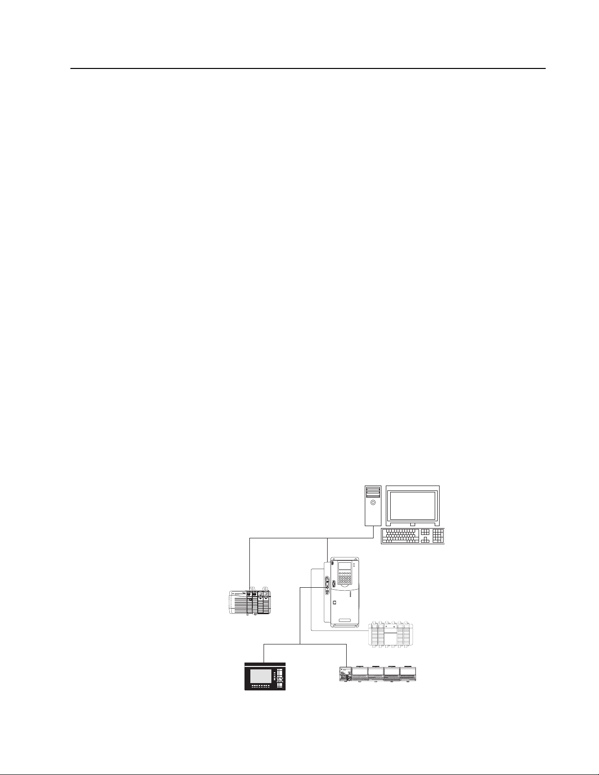
The DriveLogix controller is part of the Logix environment. The
DriveLogix controller provides a distributed control system built on these
components:
• The DriveLogix5730 controller has one RS-232 port. The controller
supports the Logix instructions.
• RSLogix 5000 programming software that supports every Logix
controller.
• Direct connection to host PowerFlex 700S drive.
• Compact I/O modules that provide a compact, DIN-rail or panel
mounted I/O system.
• Embedded EtherNet/IP option provides communication over an
EtherNet/IP network.
• 1788 communication daughtercard that provides communication over a
standards-based ControlNet, EtherNet/IP, DeviceNet or third party
network.
ControlLogix
Controller
The newer DriveLogix5730 controller offers significant performance and
capacity improvements over the DriveLogix5720 controller. It offers:
• increased user memory up to 1.5 Mbytes
• CompactFlash for non-volatile memory storage
• extended I/O capacity up to 16 I/O modules
• integrated EtherNet/IP support, including control of distributed I/O
• Run/Rem/Prog switch
ahw0783.eps
EtherNet/IP
DriveLogix
with
Local I/O
ControlNet
Remote
Work
Station
PanelView
Flex I/O
Page 14

1-2 What is DriveLogix5730?
Loading Controller Firmware
De-energizing the Drive to Connect or Disconnect a Cable
ATTENTION: Severe injury or death can result from electrical
shock or burn. Verify that the voltage on the bus capacitors has
!
discharged before connecting to the communication ports.
Measure the DC bus voltage at the +DC & -DC terminals on the
Power Terminal Block. The voltage must be zero.
During the process of loading controller firmware you will need to connect
or disconnect a programming or network cable at the controller. You should
do this only if the drive is de-energized.
1. Turn off and lock out input power. Wait five minutes.
2. Verify that there is no voltage at the drive’s input power terminals.
3. Measure the DC bus voltage at the +DC & -DC terminals on the Power
Terminal Block. The voltage must be zero.
4. Connect or disconnect the programming or network cable.
5. Turn power back on and proceed with loading firmware.
Loading Firmware
The controller ships with working firmware. You may decide to upgrade the
firmware. To load firmware, you can use:
• ControlFlash utility that ships with RSLogix 5000 programming
software.
• AutoFlash that launches through RSLogix 5000 software when you
download a project to a controller that does not have the current
firmware.
• a 1784-CF64 CompactFlash card with valid memory already loaded.
The firmware is available with RSLogix 5000 software or you can
download it from the support website:
1. Go to: http://support.rockwellautomation.com/
2. In the left column (frame), select “Firmware Updates” under “Technical
Support.”
3. Select the desired firmware revision.
The download process will require you to enter the serial number of your
RSLogix 5000 programming software.
If you load (flash) controller firmware via the ControlFlash or AutoFlash
utilities, you need a serial or EtherNet/IP connection to the controller.
Flashing via an EtherNet/IP connection is faster than the serial connection.
Page 15
What is DriveLogix5730? 1-3
The controller’s EtherNet/IP configuration settings are maintained during a
flash process.
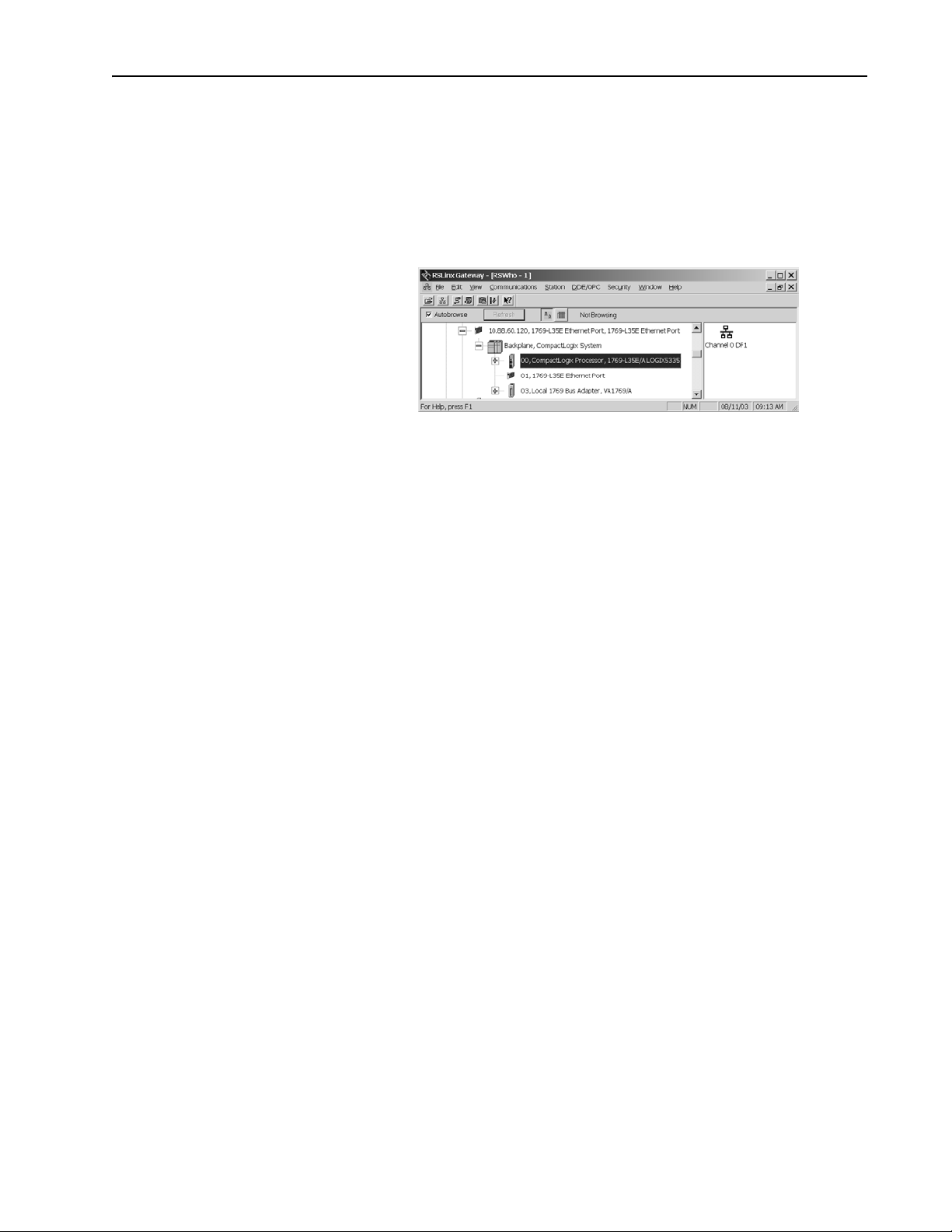
If you load firmware via an EtherNet/IP connection, browse through the
network port, across the virtual backplane, and select the appropriate
controller.
Using ControlFlash to load firmware
You can use ControlFlash to load firmware through either an Ethernet
connection (an IP address must already be assigned to the Ethernet port) or
a serial connection.
1. Make sure the appropriate network connection is made before starting.
2. Start the ControlFlash utility. Click Next when the Welcome screen
appears.
3. Select the catalog number of the controller and click Next.
4. Expand the network until you see the controller. If the required network
is not shown, first configure a driver for the network in RSLinx software.
If you use an Ethernet connection to load the firmware (which is much
faster than the serial connection), the utility will require a valid IP
address before connecting to the controller.
5. Select the controller and click OK.
6. Select the revision level to which you want to update the controller and
click Next.
7. To start the update of the controller, click Finish and then click Yes.
8. After the controller is updated, the status box displays Update complete.
Click OK.
9. To close ControlFlash software, click Cancel and then click Yes.
Page 16

1-4 What is DriveLogix5730?
Using AutoFlash to load firmware
You can use AutoFlash to load firmware through either an Ethernet
connection (an IP address must already be assigned to the Ethernet port) or
a serial connection.
1. Make sure the appropriate network connection is made before starting.
2. Use RSLogix 5000 programming software to download a controller
project. If the processor firmware does not match that project revision,
AutoFlash automatically launches.
3. Select the catalog number of the controller and click Next.
4. Expand the network until you see the controller. If the required network
is not shown, first configure a driver for the network in RSLinx software.
If you use an Ethernet connection to load the firmware (which is much
faster than the serial connection), the utility will ask for a valid IP
address before connecting to the controller.
5. Select the controller and click OK.
6. Select the revision level to which you want to update the controller and
click Next.
7. To start the update of the controller, click Finish and then click Yes.
8. After the controller is updated, the status box displays Update complete.
Click OK.
9. To close AutoFlash software, click Cancel and then click Yes.
Using a CompactFlash card to load firmware
If you have an existing DriveLogix5730 controller that is already configured
and has firmware loaded, you can store the current controller user program
and firmware on CompactFlash and use that card to update other
controllers.
1. Store the controller user program and firmware of a currently configured
DriveLogix5730 controller to the CompactFlash card.
Make sure to select Load Image On Power-up when you save to the card.
2. Remove the card and insert it into a DriveLogix5730 controller that you
want to have the same firmware and controller user program.
3. When you power up the second DriveLogix5730 controller, the image
stored on the CompactFlash card is loaded into the controller.
Page 17
What is DriveLogix5730? 1-5
Using CompactFlash
The 1784-CF64 CompactFlash card provides nonvolatile memory storage
for the DriveLogix5730 controller. The card stores the contents of the
controller memory (program logic and tag values) and the controller
firmware at the time that you store the project. Storing information to the
CompactFlash card is like storing a snapshot of controller memory at a
given time.
ATTENTION: If you configured the CompactFlash card to
“restore on power up” and you make changes to a project, such
!
as online edits or changes to tag values, you must store the
project to the CompactFlash card again after you make changes.
Otherwise, your changes are not saved and you will lose those
changes on the next power cycle to the controller.
Tag values stored in flash are a snapshot at the time of the store. During a
program restore the processor tag values will be equal to tag data stored on
flash.
The locking tab on the front of the controller helps hold the CompactFlash
card in its socket.
ATTENTION: Do not remove the CompactFlash card while the
controller is reading from or writing to the card, as indicated by a
!
flashing green CF LED. This could corrupt the data on the card
or in the controller, as well as corrupt the latest firmware in the
controller.
The CompactFlash card supports removal and insertion under power.
ATTENTION: When you insert or remove the card while
backplane power is on, an electrical arc can occur. This could
!
cause an explosion in hazardous location installations.
Be sure that power is removed or the area is nonhazardous before
proceeding. Repeated electrical arcing causes excessive wear to
contacts on both the module and its mating connector. Worn
contacts may create electrical resistance that can affect module
operation.
See the Logix5000 Controllers Common Procedures Programming Manual,
publication 1756-PM001, for steps on storing an image on the
CompactFlash card.
Page 18
1-6 What is DriveLogix5730?
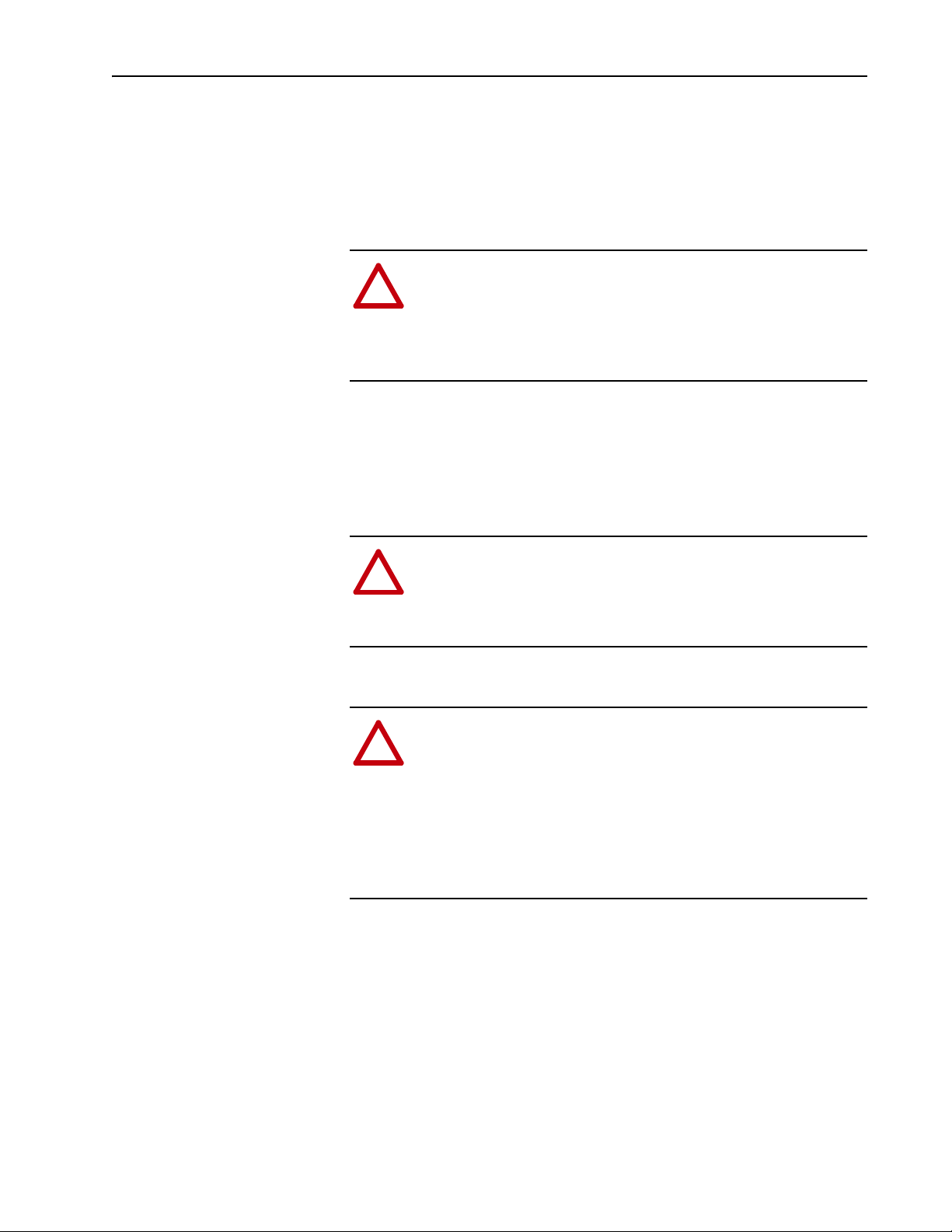
Developing Programs
The controller operating system is a preemptive multitasking system that is
IEC 1131-3 compliant. This environment provides:
• tasks to configure controller execution
• programs to group data and logic
• routines to encapsulate executable code written in a single programming
control application
task 1
program 1
main routine
language
task 8
program 32
controller fault handler
configuration
status
watchdog
program (local)
tags
fault routine
other routines
controller (global) tags I/O data system-shared data
40012.eps
Defining tasks
A task provides scheduling and priority information for a set of one or more
programs. You can configure tasks as continuous, periodic, or event. Only
one task can be continuous. The DriveLogix5730 controller supports as
many as eight tasks.
A task can have as many as 32 separate programs, each with its own
executable routines and program-scoped tags. Once a task is triggered
(activated), all the programs assigned to the task execute in the order in
which they are grouped. Programs can only appear once in the Controller
Organizer and cannot be shared by multiple tasks.
Page 19

What is DriveLogix5730? 1-7
Specifying task priorities
Each task in the controller has a priority level. The operating system uses
the priority level to determine which task to execute when multiple tasks are
triggered. You can configure periodic tasks to execute from the lowest
priority of 15 up to the highest priority of 1. A higher priority task will
interrupt any lower priority task. The continuous task has the lowest priority
and is always interrupted by a periodic task.
The DriveLogix5730 controller uses a dedicated periodic task at priority 7
to process I/O data. This periodic task executes at the Requested Packet
Interval (RPI) you configure for the CompactBus, which can be as fast as
once every 1 ms. Its total execution time is as long as it takes to scan the
configured I/O modules.
How you configure your tasks affects how the controller receives I/O data.
Tasks at priorities 1 to 6 take precedence over the dedicated I/O task. Tasks
in this priority range can impact I/O processing time. If you configure the I/
O RPI at 1ms and you configure a task of priority 1 to 6 that requires 500 µs
to execute and is scheduled to run every millisecond, this leaves the
dedicated I/O task 500 µs to complete its job of scanning the configured I/
O.
However, if you schedule two high priority tasks (1 to 6) to run every
millisecond, and they both require 500 µs or more to execute, no CPU time
would be left for the dedicated I/O task. Furthermore, if you have so much
configured I/O that the execution time of the dedicated I/O task approaches
1 ms (or the combination of the high priority tasks and the dedicated I/O
task approaches 2 ms) no CPU time is left for low priority tasks (8 to 15).
TIP: For example, if your program needs to react to inputs and control
outputs at a deterministic rate, configure a periodic task with a priority
higher than 7 (i.e., 1 through 6). This keeps the dedicated I/O task from
affecting the periodic rate of your program. However, if your program
contains a large amount of math and data manipulation, place this logic in a
task with priority lower than 7 (i.e., 8 through 15), such as the continuous
task, so that the dedicated I/O task is not adversely affected by your
program.
Important: When using a DriveLogix5730 controller with Compact I/O, all
application program tasks must have an assigned priority of 8
through 15 in order that they do not interfere with the proper
operation of the Compact I/O.
Page 20
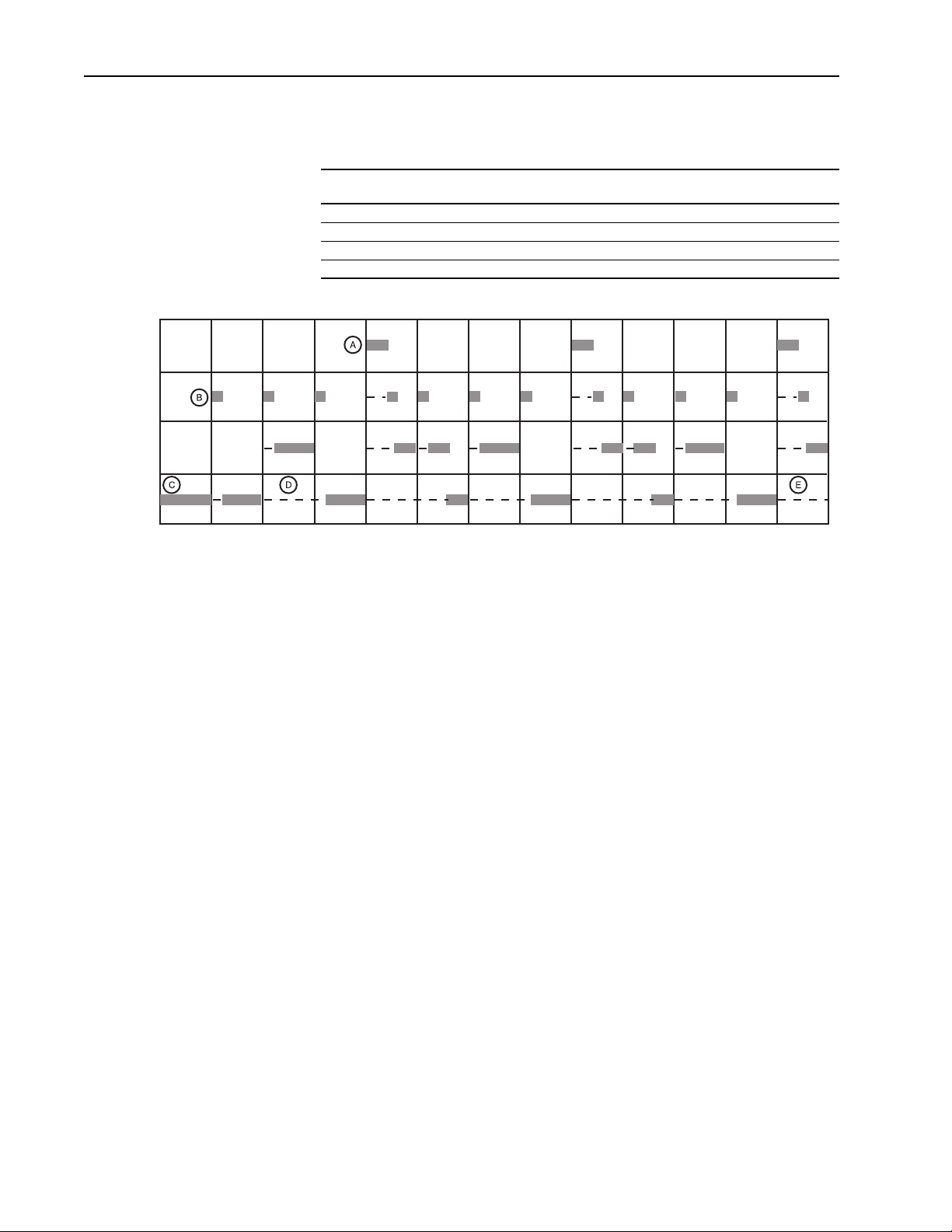
1-8 What is DriveLogix5730?
The following example shows the task execution order for an application
with two periodic tasks and one continuous task.
Example
Task: Priority Level: Task Type:
1 5 periodic task, executes every 20 ms 2 ms 2 ms
2 7 dedicated I/O task (5 ms RPI) 1 ms 3 ms
3 10 periodic task, executes every 10 ms 4 ms 8 ms
4 none (lowest) continuous task 25 ms 60 ms
Tas k 1
Tas k 2
Tas k 3
Tas k 4
030252015105 454035 50 656055
Time (ms)
Notes:
Execution Time:
A. The highest priority task interrupts all lower priority tasks.
Worst Case
Completion Time:
task_example.eps
B. The dedicated I/O task can be interrupted by tasks with priority levels 1
to 6. The dedicated I/O task interrupts tasks with priority levels 8 to 15.
This task runs at the selected RPI rate scheduled for the DriveLogix5730
system (2ms in this example).
C. The continuous task runs at the lowest priority and is interrupted by all
other tasks.
D. A lower priority task can be interrupted multiple times by a higher
priority task.
E. When the continuous task completes a full scan it restarts immediately,
unless a higher priority task is running.
Defining programs
Each program contains program tags, a main executable routine, other
routines, and an optional fault routine. Each task can schedule as many as
32 programs.
The scheduled programs within a task execute to completion from first to
last. Programs that are not attached to any task show up as unscheduled
programs. You must specify (schedule) a program within a task before the
controller can scan the program.
Page 21
What is DriveLogix5730? 1-9
Defining routines
A routine is a set of logic instructions in a single programming language,
such as ladder logic. Routines provide the executable code for the project in
a controller. A routine is similar to a program file or subroutine in a PLC or
SLC controller.
Each program has a main routine. This is the first routine to execute when
the controller triggers the associated task and calls the associated program.
Use logic, such as the Jump to Subroutine (JSR) instruction, to call other
routines.
You can also specify an optional program fault routine. The controller
executes this routine if it encounters an instruction-execution fault within
any of the routines in the associated program.
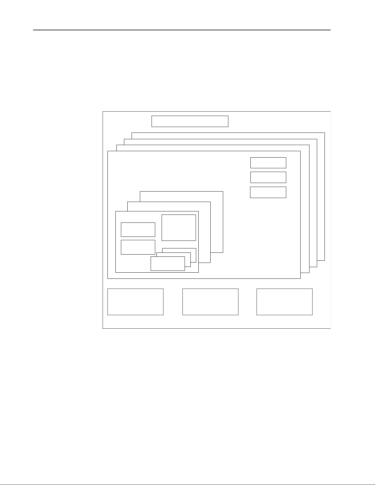
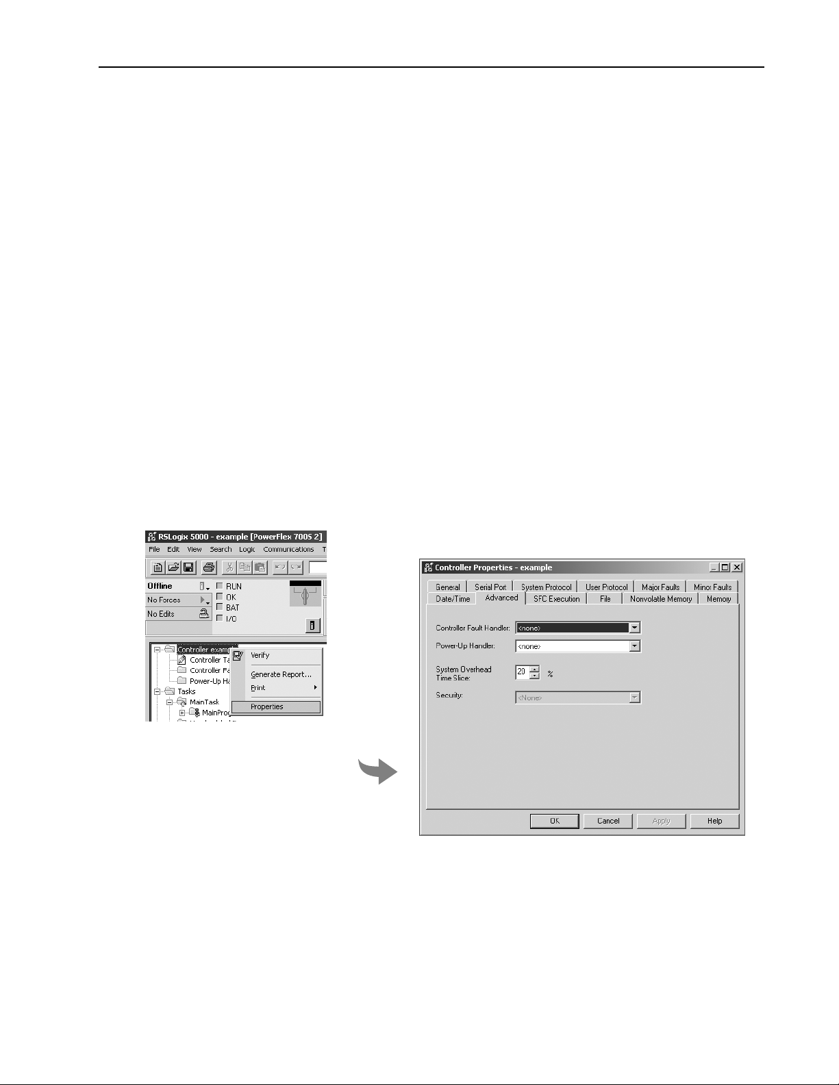
Selecting a System Overhead Percentage
1. View properties for the controller and select the Advanced
The Controller Properties dialog lets you specify a percentage for system
overhead. This percentage specifies the percentage of controller time
(excluding the time for periodic tasks) that is devoted to communication and
background functions.
ahw0757.eps
ahw0758.eps
System overhead functions include:
• communicating with programming and HMI devices (such as RSLogix
5000 software)
• responding to messages
• sending messages
Page 22
1-10 What is DriveLogix5730?
The controller performs system overhead functions for up to 1 ms at a time.
If the controller completes the overhead functions in less than 1 ms, it
resumes the continuous task.
As the system overhead percentage increases, time allocated to executing
the continuous task decreases. If there are no communications for the
controller to manage, the controller uses the communications time to
execute the continuous task. While increasing the system overhead
percentage decreases execution time for the continuous task, it does
increase communications performance. However, increasing the system
overhead percentage also increases the amount of time it takes to execute a
continuous task - increasing overall scan time.
The following table shows the ratio between the continuous task and the
system overhead functions:
At this time slice: The continuous tasks runs for: And then overhead occurs for up to:
10% 9 ms 1 ms
20% 4 ms 1 ms
33% 2 ms 1 ms
50% 1 ms 1 ms
periodic
system overhead
continuous task
TIP: For typical DriveLogix applications, a setting of 20-33% is
recommended.
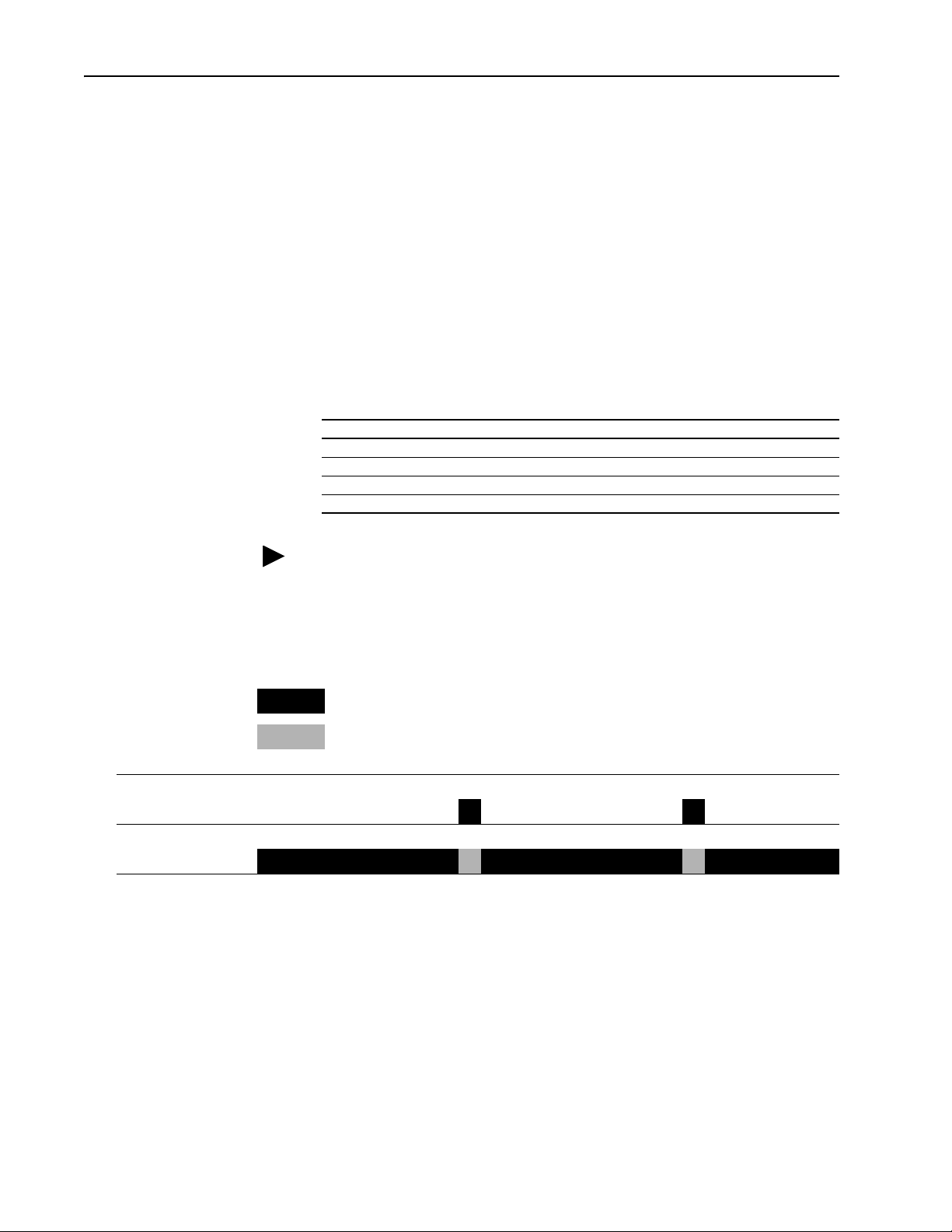
At the default time slice of 10%, system overhead interrupts the continuous
task every 9 ms (of continuous task time), as illustrated below.
Legend:
Task executes.
Task is interrupted (suspended).
1 ms 1 ms
9 ms 9 ms
0 5 10 15 20 25
elapsed time (ms)
Page 23
periodic task
system overhead
continuous task
system overhead
continuous task
What is DriveLogix5730? 1-11
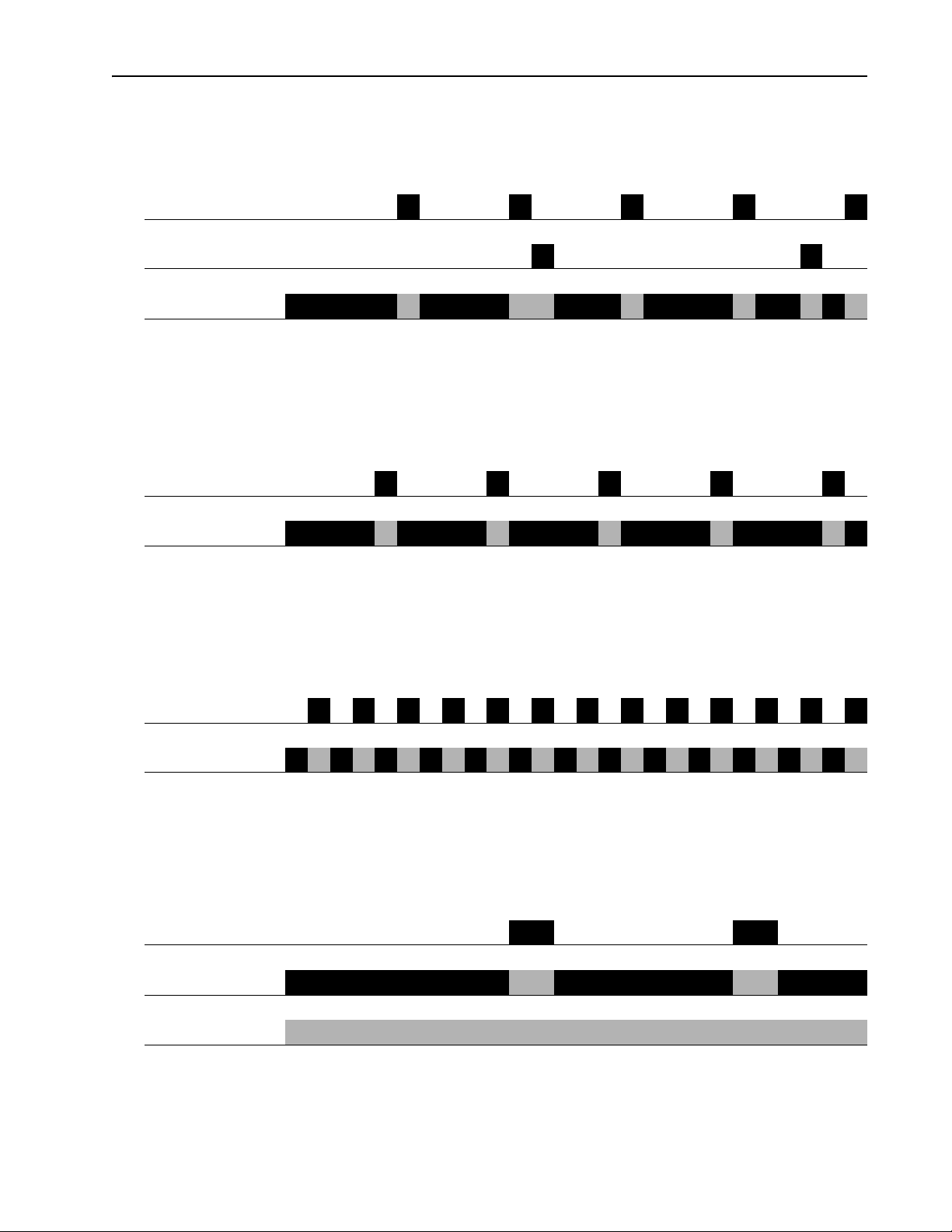
The interruption of a periodic task increases the elapsed time (clock time)
between the execution of system overhead, as shown below.
1 ms 1 ms 1 ms 1 ms 1ms
1 ms 1 ms
9 ms of continuous task time 9 ms of continuous task time
0 5 10 15 20 25
elapsed time (ms)
If you increase the time slice to 20%, the system overhead interrupts the
continuous task every 4 ms (of continuous task time).
1 ms 1 ms 1 ms 1 ms 1 ms
4 ms 4 ms 4 ms 4 ms 4 ms
5 10152025
elapsed time (ms)
system overhead
continuous task
periodic task
system overhead
continuous task
If you increase the time slice to 50%, the system overhead interrupts the
continuous task every 1 ms (of continuous task time).
1 ms
1 ms
5 10152025
elapsed time (ms)
If the controller only contains a periodic task(s), the system overhead
timeslice value has no effect. System overhead runs whenever a periodic
task is not running.
5 10152025
elapsed time (ms)
Page 24

1-12 What is DriveLogix5730?
Understanding the Virtual Backplane
The DriveLogix5730 system has a five-slot virtual backplane. The
controller, drive and other components occupy different assigned slots on
the backplane.
Virtual Backplane
Slot 0Slot 1Slot 2Slot 3Slot 4
DrvieLogix5730
Controller
Embedded
EtherNet Option
PowerFlex 700S
Drive
Compact I/O NetLinx
Daughtercard
Page 25
De-energizing the Drive to Connect or Disconnect a Cable
Chapter 2
Placing and Configuring the Drive
ATTENTION: Severe injury or death can result from electrical
shock or burn. Verify that the voltage on the bus capacitors has
!
discharged before connecting to the communication ports.
Measure the DC bus voltage at the +DC & -DC terminals on the
Power Terminal Block. The voltage must be zero.
During the process of placing and configuring the drive you will need to
connect or disconnect a programming or network cable at the controller.
You should do this only if the drive is de-energized.
1. Turn off and lock out input power. Wait five minutes.
Understanding the Interface to the Drive
2. Verify that there is no voltage at the drive’s input power terminals.
3. Measure the DC bus voltage at the +DC & -DC terminals on the Power
Terminal Block. The voltage must be zero.
4. Connect or disconnect the programming or network cable.
5. Turn power back on and proceed with placing and configuring the drive.
The DriveLogix controller supports a direct connection to the drive
consisting of 21 inputs and 21 outputs. The tag names and data types
associated with the inputs and outputs are determined by the
communication format selection. Currently, the following five
communications formats are available:
• Speed Control – for typical speed regulated applications
• Position Control – for typical positioning applications
• Motion Control - for use with Logix motion commands
• User-Defined 1 – for general use as required.
• User-Defined 2 - for general use as required.
Each communication format contains a number of pre-defined tags and
user-defined tags.
The pre-defined tag names and data types correspond with the associated
parameters, within the drive’s firmware, that are necessary to support the
selected communications format. Links must be established in the firmware,
using DriveExecutive software, to support the pre-defined tags. Linking is a
software mechanism that configures data flow within the drive’s firmware.
The links within the firmware to support the pre-defined tags are protected
Page 26

2-2 Placing and Configuring the Drive
and must be present. If the associated links are not present, or are deleted,
the communication connection between the controller and drive will be lost.
The user-defined tags are made up of a fixed number of REAL (floating
point) and DINT (double integer) data types. Links are not required within
the drive’s firmware to support these tags. Therefore, links may be created
and deleted as desired without having an affect on the communication
connection between the controller and the drive. The user-defined tags may
be used to address application specific data needs not covered by the
pre-defined tags.
Mapping for Inputs and Outputs
For each of the 21 inputs and 21 outputs, there is a dedicated parameter
within the drive, for a total of 42 parameters. Selecting a communication
format defines the data types for each input and output. It also determines
the data type for the dedicated parameter in the drive. The selection also
configures parameters 601 [From DL DataType] and 625 [To DL
DataType], which indicate the data types for each dedicated parameter
within the drive.
Determining When the Controller Updates the Drive
The DriveLogix controller follows a producer/consumer model for the drive
connection, similar to the interface to an I/O module. The drive acts as both
an input module, producing data for the controller; and an output module,
consuming data from the controller. Although the producer/consumer
model multi-casts data, all data in the drive connection is exclusive to the
DriveLogix controller.
The controller updates the input and output data in the drive connection
asynchronously to the logic scan, consistent with the way it handles other I/
O data. All input data from the drive is read in a single block and all output
data is written to the drive in a single block.
You must configure the Requested Packet Interval (RPI) rate for the drive.
This setting affects how fast the controller reads and writes the data in the
drive interface.
TIP: If you want data to remain constant throughout one scan, make a copy
of the data at the beginning of the scan and use the copy throughout the
scan.
The Drive consumes data from the DriveLogix controller every 2
milliseconds, and produces data to the controller every 2 milliseconds. The
drive updates the inputs and outputs to the controller asynchronous to both
the program scan and I/O scan of the controller.
Page 27
Placing and Configuring the Drive 2-3
Placing and Configuring the Drive
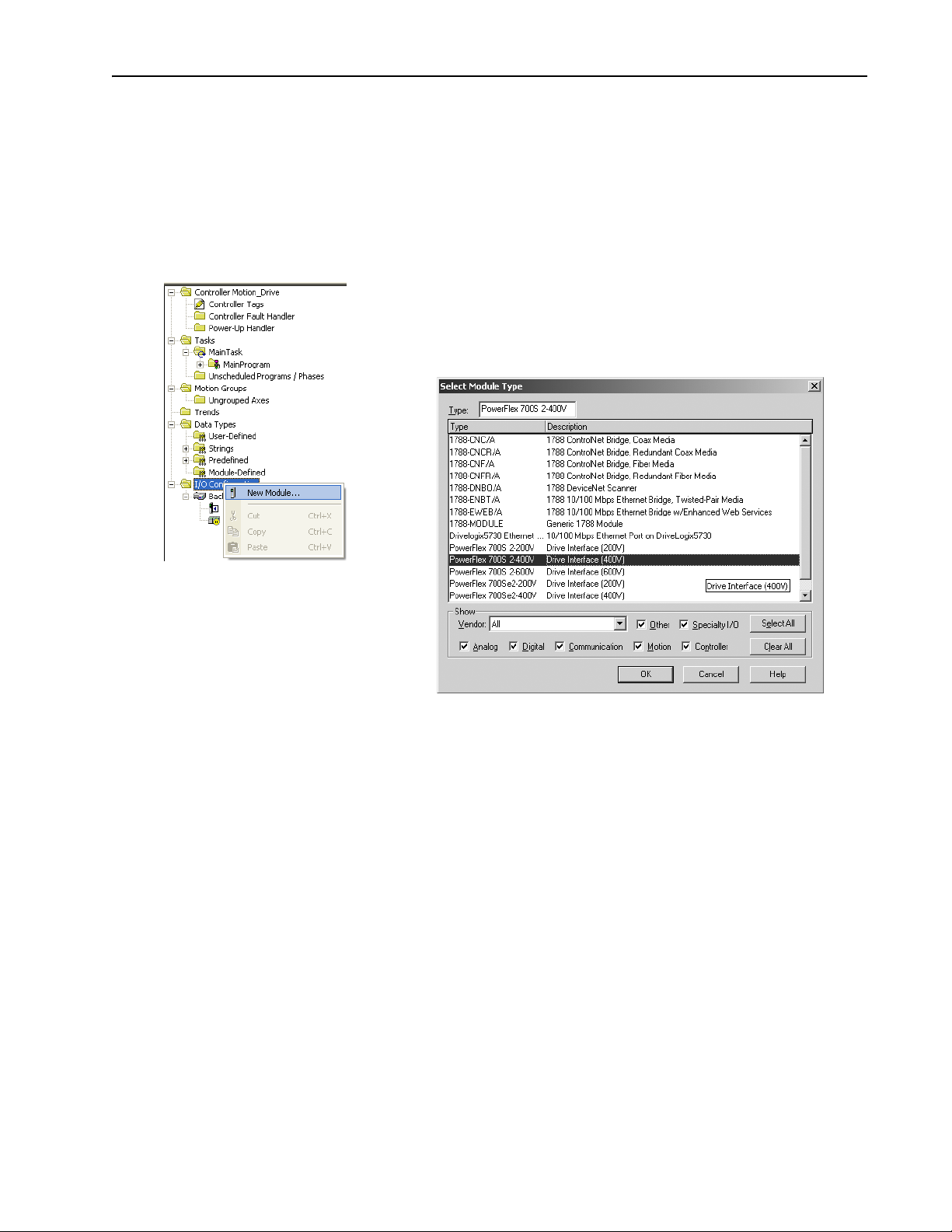
1. In the Controller Organizer, select the I/O Configuration folder. Right-click
the selected folder and select New Module.
When you create a project for the DriveLogix controller in RSLogix 5000,
the Controller Organizer automatically displays the local DIN rail for
Compact I/O. You must add the PowerFlex 700S drive to the configuration,
in a manner similar to adding an I/O module. The Controller Organizer
automatically places the drive in slot two.
2. Select the drive (PowerFlex 700S 2-400V in this example).
ahw0771.tif
ahw0772.tif
Important: You must select the correct voltage rating for the drive, when
adding the drive. You can find this on the drive data nameplate.
Page 28
2-4 Placing and Configuring the Drive
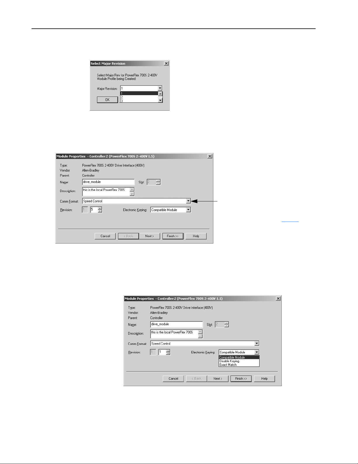
3. Select the Major Revision.
ahw0773.tif
4. Configure the drive. Use the module properties wizard to specify characteristics for the
module. Click Next to continue through the wizard.
5. Name the drive and specify the Comm Format. Click finish when you are done. The
completed module appears in the Controller Organizer.
ahw0774.tif
The selection you make for the Comm Format
determines the communication format for the
connection to the drive. This determines the
tag names and data types. See page 2-5
Once you complete adding a module, you
cannot change this selection.
Electronic Keying
Electronic keying has no effect on drive module. However, the default
setting (Compatible Module) is recommended.
ahw0775.tif
.
Selecting “Compatible Module” allows you to enter the drive firmware
minor revision.
Page 29
Placing and Configuring the Drive 2-5
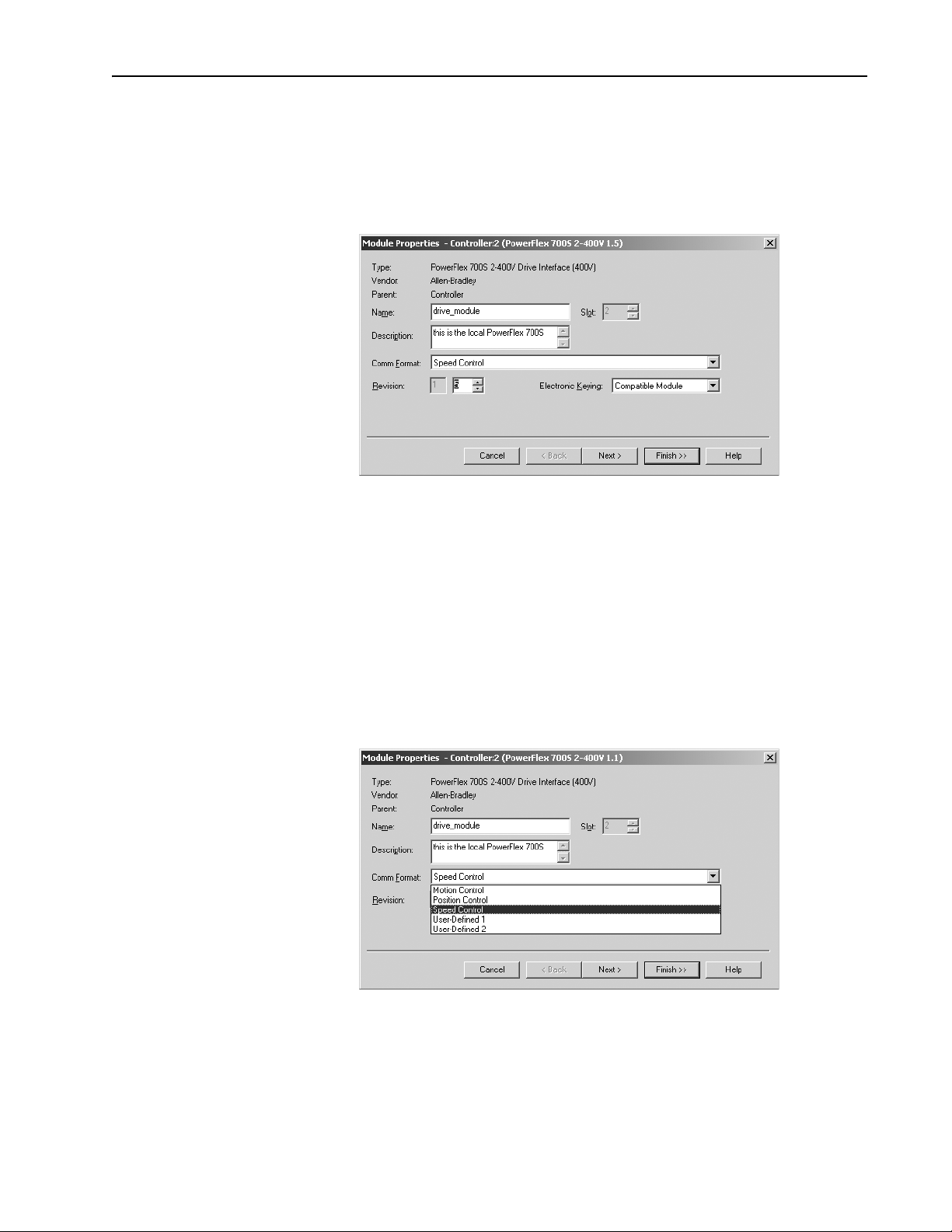
Revision
You must enter the correct drive VPL firmware revision, in order to launch
DriveExecutive and create the appropriate links for the selected
communication format. Determine the firmware revision by viewing
parameter 314 [VPL Firmware Rev] in the drive.
ahw0776.tif
Communication Formats
The communication format determines the data structure, tag names, and
required links for communication to the drive. Each communication format
has been structured to meet the requirements of a specific type of
application (Speed Control, Position Control, or general purpose), and
supports a different data structure. The links within the PowerFlex 700S
required to support the selected format are also different. Any of the
available communication formats create one direct connection to the drive.
You select the communication format when you configure the drive module.
ahw0777.tif
The default communication format for the drive is Speed Control. The tags
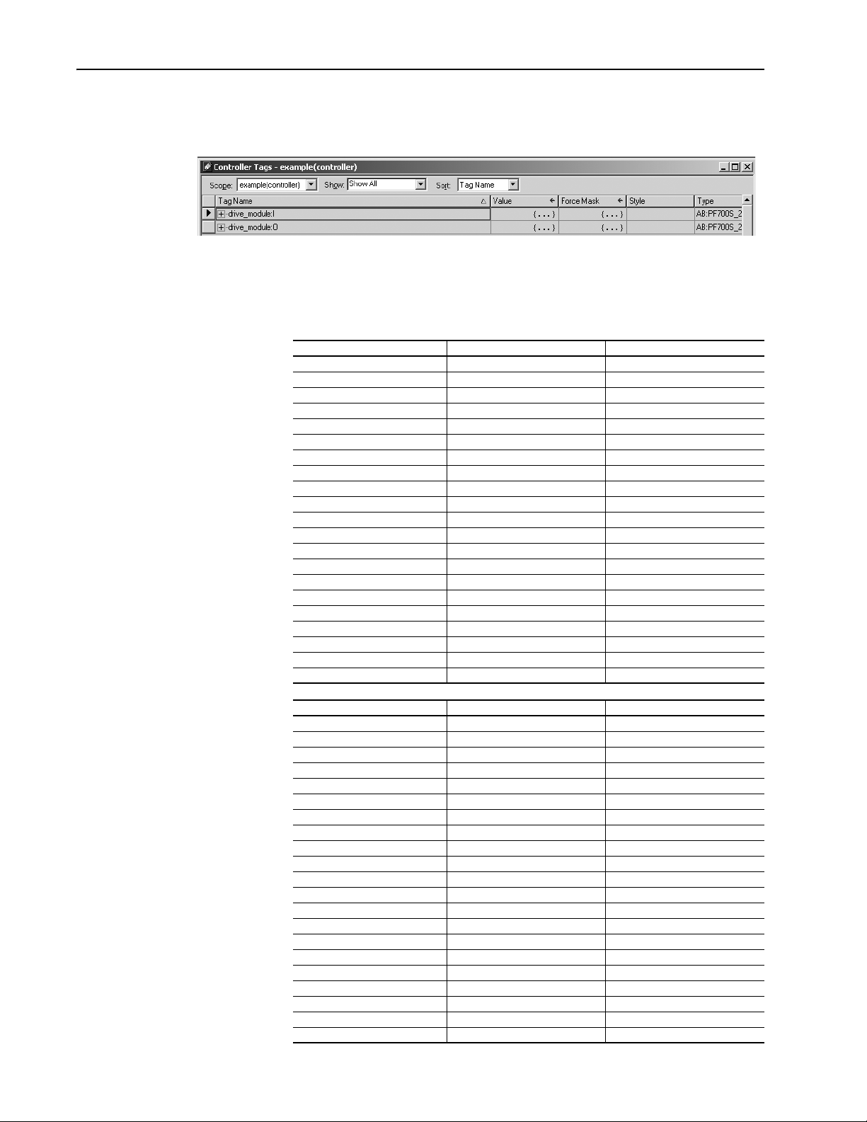
are created as controller-scoped tags. The following tag structure shows the
Page 30
2-6 Placing and Configuring the Drive
ahw0778.tif
Speed Control format. The tag structure for this example’s drive connection
has the tag name of “drive_module”.
The following tables show the tag names and their relationship to
parameters in the drive. These examples use a module name of
“drive_module”.
Table 2.A Mapping for Speed Control Communication Format
Controller Output Tag Element Drive Parameter Linked Parameter
LogicCommand 602 [FromDriveLogix00] 151 [Logic Command]
SpeedRef1 603 [FromDriveLogix01] 10 [Speed Ref 1]
TorqueRef1 604 [FromDriveLogix02] 111 [Torque Ref 1]
SpdTorqModeSelect 605 [FromDriveLogix03] 110 [Speed/TorqueMode]
TorqueStep 606 [FromDriveLogix04] 116 [Torque Step]
SpdRegDroop 607 [FromDriveLogix05] 86 [Spd Reg Droop]
UserDefinedRealData[0] 608 [FromDriveLogix06] User Defined
UserDefinedRealData[1] 609 [FromDriveLogix07] User Defined
UserDefinedRealData[2] 610 [FromDriveLogix08] User Defined
UserDefinedRealData[3] 611 [FromDriveLogix09] User Defined
UserDefinedRealData[4] 612 [FromDriveLogix10] User Defined
UserDefinedRealData[5] 613 [FromDriveLogix11] User Defined
UserDefinedRealData[6] 614 [FromDriveLogix12] User Defined
UserDefinedRealData[7] 615 [FromDriveLogix13] User Defined
UserDefinedRealData[8] 616 [FromDriveLogix14] User Defined
UserDefinedRealData[9] 617 [FromDriveLogix15] User Defined
UserDefinedIntegerData[0] 618 [FromDriveLogix16] User Defined
UserDefinedIntegerData[1] 619 [FromDriveLogix17] User Defined
UserDefinedIntegerData[2] 620 [FromDriveLogix18] User Defined
UserDefinedIntegerData[3] 621 [FromDriveLogix19] User Defined
UserDefinedIntegerData[4] 622 [FromDriveLogix20] User Defined
Controller Input Tag Element Drive Parameter Linked Parameter
LogicStatus 626 [To DriveLogix00] 155 [Logic Status]
FilteredSpdFdbk 627 [To DriveLogix01] 71 [Filtered SpdFdbk]
MotorTorqueRef 628 [To DriveLogix02] 303 [Motor Torque Ref]
OutputCurrent 629 [To DriveLogix03] 308 [Output Current]
MCStatus 630 [To DriveLogix04] 555 [MC Status]
LocalIOStatus 631 [To DriveLogix05] 824 [Local I/O Status]
UserDefinedRealData[0] 632 [To DriveLogix06] User Defined
UserDefinedRealData[1] 633 [To DriveLogix07] User Defined
UserDefinedRealData[2] 634 [To DriveLogix08] User Defined
UserDefinedRealData[3] 635 [To DriveLogix09] User Defined
UserDefinedRealData[4] 636 [To DriveLogix10] User Defined
UserDefinedRealData[5] 637 [To DriveLogix11] User Defined
UserDefinedRealData[6] 638 [To DriveLogix12] User Defined
UserDefinedRealData[7] 639 [To DriveLogix13] User Defined
UserDefinedRealData[8] 640 [To DriveLogix14] User Defined
UserDefinedIntegerData[0] 641 [To DriveLogix15] User Defined
UserDefinedIntegerData[1] 642 [To DriveLogix16] User Defined
UserDefinedIntegerData[2] 643 [To DriveLogix17] User Defined
UserDefinedIntegerData[3] 644 [To DriveLogix18] User Defined
UserDefinedIntegerData[4] 645 [To DriveLogix19] User Defined
UserDefinedIntegerData[5] 646 [To DriveLogix20] User Defined
Page 31

Placing and Configuring the Drive 2-7
Table 2.B Mapping for Position Control Communication Format
Controller Output Tag Element Drive Parameter Linked Parameter
LogicCommand 602 [FromDriveLogix00] 151 [Logic Command]
SpeedRef1 603 [FromDriveLogix01] 10 [Speed Ref 1]
PositionControl 604 [FromDriveLogix02] 740 [Position Control]
CoarsePositTrgt 605 [FromDriveLogix03] 748 [CoarsePosit Trgt]
PtPtPositRef 606 [FromDriveLogix04] 758 [Pt-Pt Posit Ref]
PositOffset1 607 [FromDriveLogix05] 753 [Posit Offset 1]
UserDefinedRealData[0] 608 [FromDriveLogix06] User Defined
UserDefinedRealData[1] 609 [FromDriveLogix07] User Defined
UserDefinedRealData[2] 610 [FromDriveLogix08] User Defined
UserDefinedRealData[3] 611 [FromDriveLogix09] User Defined
UserDefinedRealData[4] 612 [FromDriveLogix10] User Defined
UserDefinedRealData[5] 613 [FromDriveLogix11] User Defined
UserDefinedRealData[6] 614 [FromDriveLogix12] User Defined
UserDefinedRealData[7] 615 [FromDriveLogix13] User Defined
UserDefinedRealData[8] 616 [FromDriveLogix14] User Defined
UserDefinedIntegerData[0] 617 [FromDriveLogix15] User Defined
UserDefinedIntegerData[1] 618 [FromDriveLogix16] User Defined
UserDefinedIntegerData[2] 619 [FromDriveLogix17] User Defined
UserDefinedIntegerData[3] 620 [FromDriveLogix18] User Defined
UserDefinedIntegerData[4] 621 [FromDriveLogix19] User Defined
UserDefinedIntegerData[5] 622 [FromDriveLogix20] User Defined
Controller Input Tag Element Drive Parameter Linked Parameter
LogicStatus 626 [To DriveLogix00] 155 [Logic Status]
FilteredSpdFdbk 627 [To DriveLogix01] 71 [Filtered SpdFdbk]
OutputCurrent 628 [To DriveLogix02] 308 [Output Current]
LocalIOStatus 629 [To DriveLogix03] 824 [Local I/O Status]
PositionStatus 630 [To DriveLogix04] 741 [Position Status]
PositionFdbk 631 [To DriveLogix05] 762 [Position Fdbk]
PositionActual 632 [To DriveLogix06] 763 [Position Actual]
PositionError 633 [To DriveLogix07] 769 [Position Error]
UserDefinedRealData[0] 634 [To DriveLogix08] User Defined
UserDefinedRealData[1] 635 [To DriveLogix09] User Defined
UserDefinedRealData[2] 636 [To DriveLogix10] User Defined
UserDefinedRealData[3] 637 [To DriveLogix11] User Defined
UserDefinedRealData[4] 638 [To DriveLogix12] User Defined
UserDefinedRealData[5] 639 [To DriveLogix13] User Defined
UserDefinedIntegerData[0] 640 [To DriveLogix14] User Defined
UserDefinedIntegerData[1] 641 [To DriveLogix15] User Defined
UserDefinedIntegerData[2] 642 [To DriveLogix16] User Defined
UserDefinedIntegerData[3] 643 [To DriveLogix17] User Defined
UserDefinedIntegerData[4] 644 [To DriveLogix18] User Defined
UserDefinedIntegerData[5] 645 [To DriveLogix19] User Defined
UserDefinedIntegerData[6] 646 [To DriveLogix20] User Defined
Page 32

2-8 Placing and Configuring the Drive
Table 2.C Mapping for Motion Control Communication Format
Controller Output Tag Element Drive Parameter Linked Parameter
UserDefinedRealData[0] 602 [FromDriveLogix00] User Defined
UserDefinedRealData[1] 603 [FromDriveLogix01] User Defined
UserDefinedRealData[2] 604 [FromDriveLogix02] User Defined
UserDefinedRealData[3] 605 [FromDriveLogix03] User Defined
UserDefinedRealData[4] 606 [FromDriveLogix04] User Defined
UserDefinedRealData[5] 607 [FromDriveLogix05] User Defined
UserDefinedRealData[6] 608 [FromDriveLogix06] User Defined
UserDefinedRealData[7] 609 [FromDriveLogix07] User Defined
UserDefinedRealData[8] 610 [FromDriveLogix08] User Defined
UserDefinedRealData[9] 611 [FromDriveLogix09] User Defined
UserDefinedRealData[10] 612 [FromDriveLogix10] User Defined
UserDefinedRealData[11] 613 [FromDriveLogix11] User Defined
UserDefinedIntegerData[0] 614 [FromDriveLogix12] User Defined
UserDefinedIntegerData[1] 615 [FromDriveLogix13] User Defined
UserDefinedIntegerData[2] 616 [FromDriveLogix14] User Defined
UserDefinedIntegerData[3] 617 [FromDriveLogix15] User Defined
UserDefinedIntegerData[4] 618 [FromDriveLogix16] User Defined
UserDefinedIntegerData[5] 619 [FromDriveLogix17] User Defined
UserDefinedIntegerData[6] 620 [FromDriveLogix18] User Defined
UserDefinedIntegerData[7] 621 [FromDriveLogix19] User Defined
UserDefinedIntegerData[8] 622 [FromDriveLogix20] User Defined
Controller Input Tag Element Drive Parameter Linked Parameter
LogicStatus 626 [To DriveLogix00] 155 [Logic Status]
UserDefinedRealData[0] 627 [To DriveLogix01] User Defined
UserDefinedRealData[1] 628 [To DriveLogix02] User Defined
UserDefinedRealData[2] 629 [To DriveLogix03] User Defined
UserDefinedRealData[3] 630 [To DriveLogix04] User Defined
UserDefinedRealData[4] 631 [To DriveLogix05] User Defined
UserDefinedRealData[5] 632 [To DriveLogix06] User Defined
UserDefinedRealData[6] 633 [To DriveLogix07] User Defined
UserDefinedRealData[7] 634 [To DriveLogix08] User Defined
UserDefinedRealData[8] 635 [To DriveLogix09] User Defined
UserDefinedRealData[9] 636 [To DriveLogix10] User Defined
UserDefinedRealData[10] 637 [To DriveLogix11] User Defined
UserDefinedRealData[11] 638 [To DriveLogix12] User Defined
UserDefinedIntegerData[0] 639 [To DriveLogix13] User Defined
UserDefinedIntegerData[1] 640 [To DriveLogix14] User Defined
UserDefinedIntegerData[2] 641 [To DriveLogix15] User Defined
UserDefinedIntegerData[3] 642 [To DriveLogix16] User Defined
UserDefinedIntegerData[4] 643 [To DriveLogix17] User Defined
UserDefinedIntegerData[5] 644 [To DriveLogix18] User Defined
UserDefinedIntegerData[6] 645 [To DriveLogix19] User Defined
UserDefinedIntegerData[7] 646 [To DriveLogix20] User Defined
Page 33

Placing and Configuring the Drive 2-9
Table 2.D Mapping for User-Defined 1 Communication Format
Controller Output Tag Element Drive Parameter Linked Parameter
LogicCommand 602 [FromDriveLogix00] 151 [Logic Command]
UserDefinedRealData[0] 603 [FromDriveLogix01] User Defined
UserDefinedRealData[1] 604 [FromDriveLogix02] User Defined
UserDefinedRealData[2] 605 [FromDriveLogix03] User Defined
UserDefinedRealData[3] 606 [FromDriveLogix04] User Defined
UserDefinedRealData[4] 607 [FromDriveLogix05] User Defined
UserDefinedRealData[5] 608 [FromDriveLogix06] User Defined
UserDefinedRealData[6] 609 [FromDriveLogix07] User Defined
UserDefinedRealData[7] 610 [FromDriveLogix08] User Defined
UserDefinedRealData[8] 611 [FromDriveLogix09] User Defined
UserDefinedRealData[9] 612 [FromDriveLogix10] User Defined
UserDefinedRealData[10] 613 [FromDriveLogix11] User Defined
UserDefinedRealData[11] 614 [FromDriveLogix12] User Defined
UserDefinedRealData[12] 615 [FromDriveLogix13] User Defined
UserDefinedRealData[13] 616 [FromDriveLogix14] User Defined
UserDefinedIntegerData[0] 617 [FromDriveLogix15] User Defined
UserDefinedIntegerData[1] 618 [FromDriveLogix16] User Defined
UserDefinedIntegerData[2] 619 [FromDriveLogix17] User Defined
UserDefinedIntegerData[3] 620 [FromDriveLogix18] User Defined
UserDefinedIntegerData[4] 621 [FromDriveLogix19] User Defined
UserDefinedIntegerData[5] 622 [FromDriveLogix20] User Defined
Controller Input Tag Element Drive Parameter Linked Parameter
LogicStatus 626 [To DriveLogix00] 155 [Logic Status]
UserDefinedRealData[0] 627 [To DriveLogix01] User Defined
UserDefinedRealData[1] 628 [To DriveLogix02] User Defined
UserDefinedRealData[2] 629 [To DriveLogix03] User Defined
UserDefinedRealData[3] 630 [To DriveLogix04] User Defined
UserDefinedRealData[4] 631 [To DriveLogix05] User Defined
UserDefinedRealData[5] 632 [To DriveLogix06] User Defined
UserDefinedRealData[6] 633 [To DriveLogix07] User Defined
UserDefinedRealData[7] 634 [To DriveLogix08] User Defined
UserDefinedRealData[8] 635 [To DriveLogix09] User Defined
UserDefinedRealData[9] 636 [To DriveLogix10] User Defined
UserDefinedRealData[10] 637 [To DriveLogix11] User Defined
UserDefinedRealData[11] 638 [To DriveLogix12] User Defined
UserDefinedIntegerData[0] 639 [To DriveLogix13] User Defined
UserDefinedIntegerData[1] 640 [To DriveLogix14] User Defined
UserDefinedIntegerData[2] 641 [To DriveLogix15] User Defined
UserDefinedIntegerData[3] 642 [To DriveLogix16] User Defined
UserDefinedIntegerData[4] 643 [To DriveLogix17] User Defined
UserDefinedIntegerData[5] 644 [To DriveLogix18] User Defined
UserDefinedIntegerData[6] 645 [To DriveLogix19] User Defined
UserDefinedIntegerData[7] 646 [To DriveLogix20] User Defined
Page 34

2-10 Placing and Configuring the Drive
Table 2.E Mapping for User-Defined 2 Communication Format
Controller Output Tag Element Drive Parameter Linked Parameter
LogicCommand 602 [FromDriveLogix00] 151 [Logic Command]
UserDefinedRealData[0] 603 [FromDriveLogix01] User Defined
UserDefinedRealData[1] 604 [FromDriveLogix02] User Defined
UserDefinedRealData[2] 605 [FromDriveLogix03] User Defined
UserDefinedRealData[3] 606 [FromDriveLogix04] User Defined
UserDefinedRealData[4] 607 [FromDriveLogix05] User Defined
UserDefinedRealData[5] 608 [FromDriveLogix06] User Defined
UserDefinedRealData[6] 609 [FromDriveLogix07] User Defined
UserDefinedRealData[7] 610 [FromDriveLogix08] User Defined
UserDefinedRealData[8] 611 [FromDriveLogix09] User Defined
UserDefinedRealData[9] 612 [FromDriveLogix10] User Defined
UserDefinedRealData[10] 613 [FromDriveLogix11] User Defined
UserDefinedIntegerData[0] 614 [FromDriveLogix12] User Defined
UserDefinedIntegerData[1] 615 [FromDriveLogix13] User Defined
UserDefinedIntegerData[2] 616 [FromDriveLogix14] User Defined
UserDefinedIntegerData[3] 617 [FromDriveLogix15] User Defined
UserDefinedIntegerData[4] 618 [FromDriveLogix16] User Defined
UserDefinedIntegerData[5] 619 [FromDriveLogix17] User Defined
UserDefinedIntegerData[6] 620 [FromDriveLogix18] User Defined
UserDefinedIntegerData[7] 621 [FromDriveLogix19] User Defined
UserDefinedIntegerData[8] 622 [FromDriveLogix20] User Defined
Controller Input Tag Element Drive Parameter Linked Parameter
LogicStatus 626 [To DriveLogix00] 155 [Logic Status]
UserDefinedRealData[0] 627 [To DriveLogix01] User Defined
UserDefinedRealData[1] 628 [To DriveLogix02] User Defined
UserDefinedRealData[2] 629 [To DriveLogix03] User Defined
UserDefinedRealData[3] 630 [To DriveLogix04] User Defined
UserDefinedRealData[4] 631 [To DriveLogix05] User Defined
UserDefinedRealData[5] 632 [To DriveLogix06] User Defined
UserDefinedRealData[6] 633 [To DriveLogix07] User Defined
UserDefinedRealData[7] 634 [To DriveLogix08] User Defined
UserDefinedRealData[8] 635 [To DriveLogix09] User Defined
UserDefinedRealData[9] 636 [To DriveLogix10] User Defined
UserDefinedIntegerData[0] 637 [To DriveLogix11] User Defined
UserDefinedIntegerData[1] 638 [To DriveLogix12] User Defined
UserDefinedIntegerData[2] 639 [To DriveLogix13] User Defined
UserDefinedIntegerData[3] 640 [To DriveLogix14] User Defined
UserDefinedIntegerData[4] 641 [To DriveLogix15] User Defined
UserDefinedIntegerData[5] 642 [To DriveLogix16] User Defined
UserDefinedIntegerData[6] 643 [To DriveLogix17] User Defined
UserDefinedIntegerData[7] 644 [To DriveLogix18] User Defined
UserDefinedIntegerData[8] 645 [To DriveLogix19] User Defined
UserDefinedIntegerData[9] 646 [To DriveLogix20] User Defined
For each of the communication formats, drive_module:O.LogicCommand
and drive_module:I.LogicStatus are provided as DINT data types. In
addition to these tags, the control bits for each are also available as Boolean
values with tag names that correspond to the control bits in the drive. This
gives you the option of programming the Logic Command and Status words
at the Boolean level or as an integer value.
Not all 32-bits within parameter 151 [Logic Command], are directly visible
in the PowerFlex 700S. To view all 32-bits, refer to parameter 152 [Applied
LogicCmd].
Page 35

Placing and Configuring the Drive 2-11
Inhibiting the Drive Connection
Check the inhibit box to
inhibit the connection to
the drive
RSLogix 5000 programming software allows you to inhibit the controller’s
connection to the drive, in the same way you inhibit its connection to an I/O
module. Inhibiting the drive module shuts down the connection from the
controller to the drive. When you create the module you can choose to
inhibit it. After you have created the module you can inhibit or un-inhibit it
by manipulating its properties window.
ATTENTION: Inhibiting a drive module breaks the controller’s
connection to the drive. In this situation, the controller can
!
neither start or stop the drive, nor read the status of the drive. The
drive can continue to operate based on its parameter settings and
inputs. To avoid potential personal injury and damage to
machinery, make sure this does not create unsafe operation.
On the Connection tab during creation or in the Properties window
When you inhibit the drive module, the Controller Organizer displays a
yellow attention symbol
If you are: Inhibit the drive module to:
offline put a place holder for the drive module to indicate that configuration is not yet complete.
The inhibit status is stored in the project. When you download the project, the module is still inhibited.
online stop communication to the drive.
If you inhibit the drive while you are connected to the module, the connection to the module is closed. By default,
the PowerFlex 700S drive will fault. The data inputs to the drive will either hold last state, or reset to zero data
based on the setting of parameter 385 [Lgx CommLossData].
If you inhibit the drive but a connection to the module was not established (perhaps due to an error condition or
fault), the module is inhibited. The module status information changes to indicate that the module is inhibited and
not faulted.
over the module.
!
ahw0779.tif
If you uninhibit the drive (clear the check box), and no fault condition occurs, a connection is made to the drive.
To inhibit a module from logic, you must first read the Mode attribute for
the module using a GSV instruction. Set bit 2 to the inhibit status (1 to
Page 36

2-12 Placing and Configuring the Drive
ahw0514.tif
inhibit or 0 to uninhibit). Use a SSV instruction to write the Mode attribute
back to the module. For example:
Using DriveExecutive Lite
1. If not already done, enter the drive firmware revision. Click the Finish button to apply the
revision data.
In order to launch DriveExecutive Lite from within RSLogix 5000, the
drives power rating must be selected. The drive firmware revision must be
applied prior to selecting the power rating.
ahw0779.tif
Page 37

Placing and Configuring the Drive 2-13
2. In the Controller Organizer, select the PowerFlex 700S drive. Right-click the drive module and select Properties.
3. Select the Power tab.
4. Select the correct Drive Rating. This data can be found on the PowerFlex 700S data nameplate.
ahw0780.tif
ahw0781.tif
TIP: If your drive’s power rating does not appear as a selection, you do not
have the DriveExecutive Lite database file for your drive. To create a
database file, connect to the drive with DriveExecutive Lite. This will
automatically create the database. You can also download the database file
from http://www.ab.com/drives/data.html
Page 38

2-14 Placing and Configuring the Drive
5. Once the power rating is selected, apply your changes by selecting the Apply button.
6. Select the Setup tab.
7. Enter the file name for your DriveExecutive Lite parameter file, then click the Apply button.
ahw0784.tif
8. Click the DriveExecutive button to launch DriveExecutive Lite.
ahw0782.tif
ahw0785.tif
Page 39

9. When asked to create a new DriveExecutive Lite file, select yes.
ahw0786.tif
DriveExecutive will then launch and open the
newly created file
Placing and Configuring the Drive 2-15
ahw0787.tif
Page 40

2-16 Placing and Configuring the Drive
Viewing the Communication Interface to the Controller
DriveExecutive Lite has a setup screen that details the communication
interface between the controller and drive. From this screen, the relationship
between drive parameters and controller tags is presented for the selected
communication format. You can create additional links within the drive for
use with the user-defined tags in the controller.
1. To view the setup screen select Display DriveLogix from the Drive drop-down menu. Then select the From DriveLogix tab.
ahw0788.tif
ahw0789.tif
Page 41

2. To send additional data from the drive to the controller, go to the To DriveLogix tab.
Click the button in front of the
UserDefinedRealData[0] tag
Placing and Configuring the Drive 2-17
ahw0790.tif
ahw0791.tif
3. Select the desired source (parameter 307 [Output Voltage] in this example) in the resulting window.
Configuring the Drive’s Response to a Connection Failure or Controller
Mode Change
The drive contains several parameters that allow you to configure the drive’s
response to communication loss to the controller. From the drive’s
perspective, a communication loss can come in the following two forms.
• The controller closes the connection (for example, the connection is
inhibited).
• A general failure occurs causing the connection to time out.
Parameter 386 [Lgx OutofRunCnfg] configures the drive’s response to the
controller is removed from the Run Mode. Parameter 387 [Lgx Timeout
Page 42

2-18 Placing and Configuring the Drive
Cnfg] configures the drive’s response to a general connection failure as
detected by the drive. Parameter 388 [Lgx Closed Cnfg] configures the
drive’s response to the controller closing the connection. All of these
parameters configure the drive’s response to these exception events in the
following ways: ignore, alarm, fault and coast to stop, fault and ramp to
stop, fault and stop in current limit.
Parameter 385 [Lgx CommLossData] determines what the drive does with
data from the controller when communication is lost. It determines if the
drive resets the data to zero or holds the data in its last state.
Configure these parameters, using DriveExecutive Lite. Locate them in the
Fault/Alm Config group of the Utility file.
ahw0792.tif
Page 43

Using Existing DriveExecutive Lite Files
Before using an existing DriveExecutive Lite file, verify the firmware
revision, communication format, and power rating in the drive file match the
data entered in drive module properties in your DriveLogix application.
1. Select Properties from the Drive menu.
ahw0793.tif
Placing and Configuring the Drive 2-19
2. View the revision and ratings on the General tab of the Properties window.
3. Refer to Viewing the Communication Interface to the Controller on page 2-16, to view
the communication format.
ahw0794.tif
Page 44

2-20 Placing and Configuring the Drive
4. In RSLogix 5000, go to the Setup tab of the Proper ties window. Click the Browse button. Select the
existing DriveExecutive file (Existing Drive.dno in this example). Click the open button.
ahw0785.tif
5. Click the Apply button
and then launch DriveExecutive.
ahw0795.tif
ahw0796.tif
ahw0797.tif
Page 45

Placing and Configuring the Drive 2-21
Accessing Drive Data
Drive data is displayed as structures of multiple tags. The names and data
structures are based on the selected communication format. The
programming software automatically creates the necessary structures and
tags when you configure the drive module. Each tag name follows this
format:
ModuleName:Type.MemberName.SubMemberName.Bit
where:
This address variable: Is:
ModuleName Identifies the module name entered during the drive module
configuration
Type Type of data
I = input
O = output
MemberName Specific data from the drive; depends on the selected communication
format.
For tags associated with pre-defined data links, this name will be the
same as the corresponding parameter name in the drive.
SubMemberName Specific data related to a MemberName
Bit (optional) Specific bit of a DINT data value
Monitoring Drive Data
Refer to Communication Formats on page 2-5
The DriveLogix controller offers different levels at which you can monitor
the drive module. You can:
• configure the drive module so that the controller faults if the drive loses
its connection to the controller.
• use the programming software to display fault data
• program logic to monitor fault data so you can take appropriate action
for sample tag names.
Page 46

2-22 Placing and Configuring the Drive
Configuring the Controller’s Response to a Connection Failure
Check this box to configure the drive
module to generate a major fault if it loses
its connection to the controller
You can configure the drive module to generate a major fault in the
controller if the drive loses its connection to the controller.
ahw0798.tif
If you do not configure the major fault to occur, you should monitor the
drive module status. If the drive loses its connection to the controller:
• Outputs remain in their last
• Inputs remain in their last state
• By default the drive will fault
ATTENTION: If a drive loses its connection to the controller,
the controller and other I/O modules continue to operate based
!
on old data from the drive, and the drive can continue to operate
based on old data from the controller. To avoid potential personal
injury and damage to machinery, make sure this does not create
unsafe operation.
Configure the drive to generate a controller major fault when the drive loses
its connection to the controller. Or, monitor the status of the drive module.
Page 47

Placing and Configuring the Drive 2-23
Monitoring the drive module
Each communication format provides a drive status word that will indicate
when a drive fault or alarm occurs. To view this data through the
programming software:
1. In the Controller Organizer, select Controller Tags. Right-click on the selected icon and select Monitor Tags.
ahw0799.tif
2. Expand the data as necessary.
ahw0800.tif
Page 48

2-24 Placing and Configuring the Drive
You can write logic to monitor these bits and take appropriate action if a
fault or alarm occurs. For example, you may want a drive alarm to turn on a
warning lamp and a drive fault to sound an alarm and set the motor brake.
Example: Energizing Alarm Lamp, Siren and Brake in Response to Fault and Alarm
Status Bits
Given this configuration, the following logic checks the fault and alarm
drive status bits.
ahw0801.tif
ahw0802.tif
Page 49

Placing and Configuring the Drive 2-25
Recommended Programming Techniques
Naming Tags
Use a convention when naming tags and consistently follow it. The
following convention is used internally at Allen-Bradley:
<prefix>_<function>_<suffix>
Prefix - identifies the machine section in multi section programs
Prefix examples:
Sct1 = Section 1
Fan2 = Fan 2
RewA = Rewind A
Function - describes the function or signal
Function examples:
SpdRef = Speed Reference
FaultState = Status of a fault
Suffix - identifies the units of the signal or control status
Suffix examples:
Rpm = Rotations per Minute
Ok = status OK
Off = contact Off
Full tag examples:
Sct2_SpdRef_Fpm = Speed Reference, in feet per minute, on Section 2
Fan5_FaultState_OK = Status of fault, where 1 = OK, on Fan 5
TIP: Add descriptions for each tag when creating the tag
Page 50

2-26 Placing and Configuring the Drive
Use Aliasing for all Communication Format Connections Between
DriveLogix and the PowerFlex 700S
Using aliases for the tags in the Communication Format (i.e. Speed Control,
Motion Control, Position Control, User-Defined 1 and User-Defined 2) has
the following benefits:
• Improves program portability over processors and through upgrades to
DriveLogix, PowerFlex 700S, and RSLogix 5000 firmware.
• Allows real names to be applied to the User Defined tags of the static
assembly.
• Allows new functions of DriveLogix and the PowerFlex 700S to be
clearly named in the program even if RSLogix 5000 has not been
updated.
• Allows long tag names in RSLogix 5000 to be shortened for easier
program viewing.
• Allows tags to be named using the above naming convention to identify
machine section association.
Apply aliases to all external connections including the PowerFlex 700S
Communication Format and I/O. All defined bits should be included.
Use "Periodic Tasks" to optimize processor utilization.
Name periodic tasks to identify the update time
(e.g. Periodic_020ms_P9 = 20ms task with priority 9).
Set the periodic task time appropriate programming requirements.
Important: Remember that tasks with faster the task times consume more
processor bandwidth than those with slower task times.
Set the priority of each task to coincide with the task speed. Set faster tasks
to higher priority.
Important: Remember lower priority numbers define higher priorities (e.g.
a task with a priority number of 9 has a higher priority than one
with a priority of 10).
Important: Do not set the priority number lower than 8 (the recommended
priority range is 8-15). This will provide I/O scanning with
optimal updating. Flex I/O and Compact I/O are coded as
priority 7 for DriveLogix.
Page 51

De-energizing the Drive to Connect or Disconnect a Cable
Chapter 3
Placing and Configuring Local I/O
ATTENTION: Severe injury or death can result from electrical
shock or burn. Verify that the voltage on the bus capacitors has
!
discharged before connecting to the communication ports.
Measure the DC bus voltage at the +DC & -DC terminals on the
Power Terminal Block. The voltage must be zero.
During the process of placing and configuring I/O you will need to connect
or disconnect a programming or network cable at the controller. You should
do this only if the drive is de-energized.
1. Turn off and lock out input power. Wait five minutes.
Understanding How the DriveLogix5730 Supports I/O
ahw0803.eps
2. Verify that there is no voltage at the drive’s input power terminals.
3. Measure the DC bus voltage at the +DC & -DC terminals on the Power
Terminal Block. The voltage must be zero.
4. Connect or disconnect the programming or network cable.
5. Turn power back on and proceed with placing and configuring the I/O.
The DriveLogix5730 controller supports up to 2 banks of modules with a
maximum of 8 modules per bank. You must distribute the modules within
each bank so that no more than 4 modules are on either side of the power
supply.
Powe r Module
I/O Modules
I/O Modules
Page 52

3-2 Placing and Configuring Local I/O
Placing Local I/O Modules
Refer to the Compact I/O Selection Guide, publication 1769-SG001, for
information about selecting Compact I/O modules. Use the 20D-DL2-CR3
or 20D-DL2-CL3 cables to connect a DriveLogix5730 controller to a bank
of Compact I/O. Use 1769-CRR1/-CRR3 or 1769-CRL1/-CRL3 expansion
cable to connect banks of I/O modules. You can split a bank right after the
power supply or after any I/O module. Each bank must contain one power
supply. An end cap/terminator must be used on the last I/O bank opposite of
the expansion cable.
Only the local DriveLogix5730 controller can scan the local Compact I/O.
ATTENTION: The Compact I/O system does not support
!
Removal and Insertion Under Power (RIUP).
While the DriveLogix / Compact I/O is under power:
• any break in the connection between the power supply
and the controller (i.e. removing the power supply,
controller, or an I/O module) may subject the logic
circuitry to transient conditions above the normal design
thresholds and may result in damage to system
components or unexpected behavior.
• removing an end cap or a module fault may fault the
controller.
A 20D-DL2-CL3 cable connects the controller to the left side of an I/O
bank. A 20D-DL2-CR3 cable connects the controller to the right side of an
I/O bank.
ahw0804.eps
20D-DL2-CL3
ahw0805.eps
20D-DL2-CR3
Page 53

Placing and Configuring Local I/O 3-3
A 1769-CRL1/-CRL3 connects the left side of one bank of Compact I/O to
the right side of another. This facilitates a horizontal I/O orientation.
20D-DL2-CL3 1769-CRLX
ahw0806.eps
A 1769-CLL1/-CLL3 connects the left side of one bank of Compact I/O to
the left side of another. A 1769-CRR1/-CRR3 connects the right side of one
bank of Compact I/O to the right side of another. This facilitates a vertical
I/O orientation.
ahw0808.eps
ahw0807.eps
20D-DL2-CR31769-CRLX
ahw0809.eps
Validating I/O Layout
20D-DL2-CL3
1769-CRRX
To validate your planned I/O layout, consider these requirements:
• Each module in a Compact I/O system uses a set amount of backplane
memory, in addition to the data that the module stores or transfers. As
you add modules, the minimum backplane RPI increases.
• The I/O modules must be distributed such that the current consumed
from the left or right side of the power supply never exceeds 2.0A at 5V
dc and 1.0A at 24V dc.
1769-CLLX
20D-DL2-CR3
Page 54

3-4 Placing and Configuring Local I/O
Estimating RPI
Determining When the Controller Updates I/O
As you install modules, the minimum backplane RPI increases. The RPI
(request packet interval) defines the frequency at which the controller sends
and receives all I/O data on the backplane. There is one RPI for the entire
1769 backplane. Consider these guidelines when installing modules:
Type of Module: Considerations:
digital and analog
(any mix)
specialty • “full-sized” 1769-SDN modules add 1.5 ms per module
You can always select an RPI that is slower than listed above. These
considerations show how fast modules can be scanned - not how fast an
application can use the data. The RPI is asynchronous to the program scan.
Other factors, such as program execution duration, affect I/O throughput.
The controller continually scans the control logic. One scan is the time it
takes the controller to execute the logic once. Input data transfers to the
controller and output data transfers to output modules are asynchronous to
the logic scan.
• 1-4 modules can be scanned in 1.0 ms
• 5-16 modules can be scanned in 1.5 ms
• some input modules have a fixed 8.0 ms filter, so selecting a faster
RPI has no affect
• 1769-HSC modules add 0.5 ms per module
TIP: If you need to ensure that the I/O values being used during logic
execution are from one moment in time (such as at the beginning of a ladder
program), use the Synchronous Copy instruction (CPS) to buffer I/O data.
Refer to the Logix5000 Controllers Common Procedures Programming
Manual, publication number 1756-PM001 for examples of I/O buffering or
to the Logix5000 Controllers General Instruction Set Reference Manual,
publication number 1756-RM003 for information on the CPS instruction.
Page 55

Placing and Configuring Local I/O 3-5
Configuring the CompactBus
1. In the Controller Organizer, select CompactBus Local icon. Right click and
select Properties.
When you create a DriveLogix5730 project, the programming software
automatically creates the local CompactBus. You must configure the
CompactBus.
ahw0811.tif
ahw0810.tif
Page 56

3-6 Placing and Configuring Local I/O
On the General tab, specify the size of the chassis. Enter the number of
modules you plan to install. Include the DriveLogix5730 controller and
drive in this total, along with a maximum of 16 I/O modules, not including
the power supply.
The Comm Format for the CompactBus is automatically set to Rack
Optimized and cannot be changed.
Using the Connection tab, you can specify the RPI for the systems and
choose to inhibit or uninhibit the CompactBus.
ahw0812.tif
The RPI you specify here is the RPI for every 1769 module on this
controller’s local CompactBus. Specify an RPI from 1-750ms for the
system. You do not specify individual RPI values for each module.
By inhibiting and uninhibiting the CompactBus, you can write new
configuration data to the entire system at once.
The controller’s response to a CompactBus connection failure is dependant
upon the Compact I/O modules configuration. The checkbox which
indicates that the controller will fault should be ignored - for the
CompactBus adapter. Furthermore, if any Compact I/O module is
configured to fault the module on connection loss, any Compact I/O module
fault will cause the controller to fault.
Page 57

Placing and Configuring Local I/O 3-7
Configuring Local I/O Modules
1. In the Controller Organizer, select CompactBus Local icon. Right click and
select New Module.
2. Select the new module (1769-IA16 in this example).
Use your programming software to configure the I/O modules for the
controller.
ahw0814.tif
ahw0813.tif
3. Configure the module, using the module wizard to specify characteristics. Click Next to advance the wizard. Click Finish
when you are done.
ahw0815.tif
The completed module will appear in the Controller Organizer.
Page 58

3-8 Placing and Configuring Local I/O
ahw0816.tif
Communication Formats
The communication format determines the data structure the I/O module
uses. Each format supports a different data structure. Presently, the
DriveLogix5730 controller supports two data formats:
• Input Data – INT (for 1769 input modules)
• Data – INT (for 1769 output modules)
TIP: The DriveLogix5730 controller must own its local I/O modules. No
other Logix-based controller can own the local Compact I/O.
The communication format determines the tag structure that is created for
the module. Assume that a 1769-IA16 Input module is in slot 1. The
software creates the appropriate tags using the slot number to differentiate
the tags for this example module from any other module.
Hold Last State and User-Defined Safe State Not Supported
ATTENTION: Risk of injury or equipment damage exists.
When 1769 Compact I/O modules are used as local I/O modules
!
in a DriveLogix5730 system, the local I/O modules do not
support the Hold Last State or User-Defined Safe State features,
even though you can configure these options in the programming
software. Precautions should be taken to ensure that these
settings do not create a hazard of injury or equipment damage.
When a compact I/O module is configured to do so, it will cause the
controller to go into a faulted mode when the compact I/O module fails and
communication to the controller is lost, or the compact I/O module is
Page 59

Placing and Configuring Local I/O 3-9
disconnected from the system bus while under power. All outputs turn off
when the system bus or any module faults.
RSLogix 5000 software creates tags for modules when you add them to the
I/O configuration. The 1769 module tags define configuration (C) data type
members which may include attributes for alternate outputs.
DriveLogix5730 does not enable local modules to use the alternate outputs.
Do not configure the attributes listed below:
For digital output modules: For analog output modules:
• ProgToFaultEn
• ProgMode
• ProgValue
• FaultMode
• FaultValue
Any 1769 Compact I/O modules used as remote I/O modules in a
DriveLogix5730 system do support the Hold Last State and User-Defined
Safe State features.
• CHxProgToFaultEn
• CHxProgMode
• CHxFaultMode
• where CHx = the channel number
Inhibiting I/O Module Operation
In some situations, such as when initially commissioning a system, it is
useful to disable portions of a control system and enable them as you wire
up the control system. The controller lets you inhibit individual modules or
groups of modules, which prevents the controller from trying to
communicate with these modules. Inhibiting a module shuts down the
connection from the controller to that module.
When you create an I/O module, it defaults to being not inhibited. You can
change an individual module’s properties to inhibit a module.
ATTENTION: Inhibiting a module causes the connection to the
module to be broken and prevents communication of I/O data.
!
The controller and other I/O modules continue to operate based
on old data from that module. To avoid potential injury and
damage to machinery, make sure this does not create unsafe
operation.
Page 60

3-10 Placing and Configuring Local I/O
On the Connection tab of the Module Properties dialog, you can select to
inhibit that specific module.
ahw0817.tif
TIP: To easily inhibit all local I/O modules, you can inhibit the
CompactBus, which in turn inhibits all the modules on that bus. See
Configuring the CompactBus on page 3-5
When you select to inhibit a module, the controller organizer displays a
If you are: Inhibit a module to:
offline put a place holder for a module you are configuring.
online stop communication to a module.
yellow circle symbol over the module.
The inhibit status is stored in the project. When you download the project, the module is still inhibited.
If you inhibit a module while you are connected to the module, the connection to the module is
closed. The module’s outputs turn off.
If you inhibit a module but a connection to the module was not established (perhaps due to an error
condition or fault), the module is inhibited. The module status information changes to indicate that the
module is inhibited and not faulted.
If you uninhibit a module (clear the check box), and no fault condition occurs, a connection is made to
the module and the module is dynamically reconfigured with the configuration you created for that
module.
If you uninhibit the module and a fault condition occurs, a connection is not made to the module. The
module status information changes to indicate the fault condition.
.
To inhibit a module from logic, you must first read the Mode attribute for
the module using a GSV instruction. Set bit 2 to the inhibit status (1 to
Page 61

Placing and Configuring Local I/O 3-11
inhibit or 0 to uninhibit). Use a SSV instruction to write the Mode attribute
back to the module. For example:
The GSV instruction gets the current status of the module named “input_module.” The SSV instruction sets the state of “input_module” as either
inhibited or uninhibited.
When on, inhibits the module.
When off, uninhibits the module.
Sending Module Configuration Information
The controller sends module configuration information once module
connections are established.
ATTENTION: If you make a configuration change to any
module in the system do one of the following to resend module
!
configuration data:
• cycle power to the controller
• inhibit and then uninhibit the bus
• inhibit and then uninhibit the individual module
• send a MSG instruction of type Module Reconfigure (for
information on configuring a MSG to send configuration data,
see the Logix5000 Controllers General Instructions Reference
Manual, publication 1756-RM003)
GSV ladder.tif
Page 62

3-12 Placing and Configuring Local I/O
Configuring the Controller’s Response to a Connection Failure
In a DriveLogix5730 system, the controller’s response to a CompactBus
connection failure is dependant on the setting of the individual compact I/O
modules.
Important: The controller’s response to a connection failure of any I/O
module is dependant on the configuration of the I/O modules. If
any I/O module has the "Major Fault On Controller If
Connection Fails While in Run Mode" checkbox selected, the
controller will fault on any I/O fault.
ahw0817.tif
Accessing I/O Data
The I/O modules respond to a connection failure by turning off output.
The programming software displays I/O data as structures of multiple tags
that depend on the specific features of the I/O module. The names of the
data structures are based on the location of the I/O module. The
programming software automatically creates the necessary structures and
tags when you configure the module. Each tag name follows this format:
Location:SlotNumber:Type.MemberName.SubMemberName.Bit
where:
This address variable: Is:
Location Identifies network location
LOCAL = local chassis
SlotNumber Slot number of I/O module in its chassis
Type Type of data
I = input
O = output
C = configuration
Page 63

Placing and Configuring Local I/O 3-13
This address variable: Is:
MemberName Specific data from the I/O module; depends on the type of data the
module can store
For example, Data and Fault are possible fields of data for an I/O
module. Data is the common name for values that are sent to or
received from I/O points.
SubMemberName Specific data related to a MemberName.
Bit (optional) Specific point on the I/O module; depends on the size of the I/O
module (0-31 for a 32-point module)
The following examples show addresses for data in a DriveLogix5730
system.
Example:
I/O module on the local CompactBus utilizing two banks
ahw0818.eps
12 345
Bank 1 Bank 2
Page 64

3-14 Placing and Configuring Local I/O
Sample tag names for this example:
Location: Example Tag Name:
input module in slot 1, LOCAL Bank 1 Local:1:C
Local:1:I
output module in slot 2, LOCAL Bank 1 Local:2:C
Local:2:I
Local:2:O
analog input module in slot 3, LOCAL Bank 2 Local:3:C
Local:3:I
analog output module in slot 4, LOCAL Bank 2 Local:4:C
Local:4:I
Local:4:O
analog input module in slot 5, LOCAL Bank 2 Local:5:C
Local:5:I
Using aliases to simplify tag names
An alias lets you create a tag that represents another tag. This is useful for
defining descriptive tag names for I/O values. For example:
Direct Connections for I/O Modules
Example: Description:
I/O structure Local:1:I:Data[0].0
Local:1:I:Fault.0
alias light_on = Local:1:I:Data[0].0
module_failed = Local:1:I:Fault.0
Each local I/O module uses a direct connection to the DriveLogix5730
controller. A direct connection is a real-time, data transfer link between the
controller and an I/O module. The controller maintains and monitors the
connection between the controller and the I/O module. Any break in the
connection, such as a module fault, causes the controller to set fault status
bits in the input data area associated with the module.
ATTENTION: The DriveLogix5730 controller does not support
Removal and Insertion Under Power (RIUP). While the
!
DriveLogix5730 system is under power:
• any break in the connection between the power supply and the
controller (i.e. removing the power supply, controller, or an I/
O module) may subject the logic circuitry to transient
conditions above the normal design thresholds and may result
in damage to system components or unexpected behavior.
• removing an end cap or an I/O module may fault the
controller and may also result in damage to system
components.
The aliases describe the specific I/O
points.
Page 65

Placing and Configuring Local I/O 3-15
Monitoring I/O Modules
ahw0819.tif
The DriveLogix5730 controller offers different levels at which you can
monitor I/O modules. You can:
• use the programming software to display fault data (See Displaying Fault
Data on page 3-15)
• program logic to monitor fault data so you can take appropriate action
(Refer to Logix5000 Controllers Common Procedures Programming
Manual, publication number 1756-PM001, for examples.)
Displaying Fault Data
Fault data for certain types of module faults can be viewed through the
programming software.
To view this data, select Controller Tags in the Controller Organizer.
Right-click to select Monitor Tags.
Page 66

3-16 Placing and Configuring Local I/O
The display for the fault data defaults to decimal. Change it to Hex to read
the fault code.
If the module faults, but the connection to the controller remains open, the
controller tags database displays the fault value 16#0E01_0001. The fault
word uses this format:
31
fault_word.eps
Bit Description
Fault_Bit This bit indicates that at least one bit in the fault word is set (1). If all the bits in the fault word are
Connection_Closed This bit indicates whether the connection to the module is open (0) or closed (1). If the connection
27 19 11
Fault_Code_Value
23 15
reserved
FaultInfoFaultCodereserved
0 = connection open
1 = connection closed
Where:
cleared (0), this bit is cleared (0).
is closed (1), the Fault_Bit it set (1).
You can also view module fault data on the Connection tab of the Module
Properties screen.
}
Connection_Closed
70
Fault_Bit
3
ahw0817.tif
See your 1769 module’s user documentation for a description of module
faults. To recover from module faults, correct the module fault condition
and send new data to the module by downloading the user program with
configuration data, inhibiting and then uninhibiting the module, or cycling
power.
Page 67

Placing and Configuring Local I/O 3-17
End-cap Detection and Module Faults
If a module that is not adjacent to an end cap experiences a fault and the
connection to the controller is not broken, only the module enters the fault
state.
If a module that is adjacent to an end cap experiences a fault, the module
will fault and the controller may fault.
Configuring I/O Modules Using the Generic 1769-MODULE
1. In the Controller Organizer, select CompactBus Local icon. Right click and
select New Module.
Use the Generic 1769 Module only when a 1769 I/O module does not
appear in the list of modules to add to the Controller Organizer. To
configure a 1769 I/O module for a DriveLogix5730 controller using the
generic 1769-MODULE:
2. Select the 1769-MODULE (Generic 1769 Module).
ahw0813.tif
ahw0820.tif
Page 68

3-18 Placing and Configuring Local I/O
3.Configure the module, using the module wizard to specify characteristics. Click Next to advance the wizard. Click Finish
when you are done.
The completed module will appear in the
Controller Organizer.
The generic module requires
you to specify more
parameters of the module.
Important: The values you enter for these parameters are device specific.
See the documentation for the device to determine which values
to enter.
ahw0821.tif
On the generic module screen, you define the parameters of the module.
In this field: Specify:
Name name of the module
Description (optional) provide more details about the module
Comm Format communication format
Slot slot placement of the module on the CompactBus
Connection Parameters
Input
Output
Configuration
1769 analog output modules, digital output modules, analog combination modules, and digital
combination modules, use Data – INT.
1769 analog input modules and digital input modules use Input Data – INT.
connection information unique to the module
The documentation for module should list the assembly instance and size numbers for the input,
output, and configuration parameters.
Page 69

Entering the Configuration Information for the Module
1.In the Controll
Once you configure a module using the generic 1769-MODULE, you must
enter the configuration information for the module into the tag database.
The configuration information is downloaded to the module at program
download, power up, and whenever a module is inhibited and then
uninhibited.
er Organizer, double-click on Controller Tags.
2. Edit the tags for the module so that the tags contain the appropriate configuration
Placing and Configuring Local I/O 3-19
ahw0822.tif
ahw0823.tif
The generic module was added to slot 3, so you want to enter
configuration data into the Local:3:C tags.
RSLogix 5000 programming software automatically create tags for
configured I/O modules. All local I/O addresses are preceded by the word
Local. These addresses have the following format:
• Input Data: Local:s:I
• Output Data: Local:s:O
• Configuration Data: Local:s:C
Where s is the slot number assigned the I/O module.
Open the configuration tag for that module by clicking on the plus sign to
the left of its configuration tag in the tag database. The configuration
information depends on the module. See the documentation on the I/O
module for the appropriate configuration information.
Page 70

3-20 Placing and Configuring Local I/O
Notes:
Page 71

De-energizing the Drive to Connect or Disconnect a Cable
Chapter 4
Configuring DriveLogix Motion
ATTENTION: Severe injury or death can result from electrical
shock or burn. Verify that the voltage on the bus capacitors has
!
discharged before connecting to the communication ports.
Measure the DC bus voltage at the +DC & -DC terminals on the
Power Terminal Block. The voltage must be zero.
During the process of configuring DriveLogix motion you will need to
connect or disconnect a programming or network cable at the controller.
You should do this only if the drive is de-energized.
1. Turn off and lock out input power. Wait five minutes.
About this Chapter
System Requirements
2. Verify that there is no voltage at the drive’s input power terminals.
3. Measure the DC bus voltage at the +DC & -DC terminals on the Power
Terminal Block. The voltage must be zero.
4. Connect or disconnect the programming or network cable.
5. Turn power back on and proceed with configuring DriveLogix motion.
This chapter introduces DriveLogix5730 motion. The steps in this chapter
provide the minimum settings required to begin testing DriveLogix motion.
• PowerFlex 700S Phase II Drive with firmware revision 2.XX or higher
• DriveLogix5730 Controller with firmware revision 15.XX or higher
• DriveExecutive programming software version 3.02 or higher
• RSLogix 5000 programming software version 15 or higher
Page 72

4-2 Configuring DriveLogix Motion
Programming the Controller
In RSLogix 5000, create a new project.
1. From the File menu, select New.
2. In the New Controller dialog define the project:
a. Use Revision 15 or higher.
b. Enter a Name for the project (e.g., Motion_Drive).
c. Click the OK button.
Page 73

3. In the Controller Organizer:
a. Right-click on the I/O Configuration folder.
b. Select New Module from the menu.
Configuring DriveLogix Motion 4-3
4. In the Select Module dialog, click the plus sign (+) next to Drives to
expand the selection.
Page 74

4-4 Configuring DriveLogix Motion
5. Select the desired drive (PowerFlex 700S 2-400V in this example) and
click the OK button.
6. In the Major Revision dialog:
a. Select the Major Revision number and click the OK button.
7. Configure the Drive by specifying the characteristics of the module
using the New Module dialog:
a. Enter a name for the drive in the Name field (Drive_Axis in this
example).
a. Select Motion Control in the Comm Format box.
b. Verify that the Open Module Properties box is checked.
c. Click the OK button.
Page 75

Configuring DriveLogix Motion 4-5
8. On the Connections tab of the Modules Properties dialog:
a. Change the value on the Requested Packet Interval (RPI) box to
3.0 ms.
b. Click on the Associated Axis tab and click the New Axis button to
assign a channel to Axis00.
c. In the New Tag dialog, create a new tag structure for Axis00 by
typing Axis00 in the Name field and clicking the OK button.
d. On the Associated Axis tab, click the New Axis button to assign a
channel to Axis01.
Page 76

4-6 Configuring DriveLogix Motion
e. In the New Tag dialog, create a new tag structure for Axis01 by
typing Axis01 in the Name field and clicking the OK button.
f. On the Associated Axis tab, click the drop-down arrow next to
Channel 0 (Primary) and select Axis00.
g. On the Associated Axis tab, click the drop-down arrow next to
Channel 1 (Auxiliary) and select Axis01.
Page 77

Configuring DriveLogix Motion 4-7
9. Click on the Power tab and select the proper Drive Rating.
10. Click the Apply button.
11. Click the OK button.
12. Create a new Motion Group.
a. In the Controller Organizer, right-click on Motion Groups.
b. Select New Motion Group from the menu.
Page 78

4-8 Configuring DriveLogix Motion
c. Enter a Name for the Motion Group (Grouped_Axis in this
example).
d. Verify that the Open MOTION_GROUP Configuration box is
checked.
e. Click on the OK button.
13. In the Motion Group Wizard dialog, move each axis from the
Unassigned box to the Assigned box by clicking on the axis name and
then clicking the Add button.
14. Click the Next button.
Page 79

Configuring DriveLogix Motion 4-9
15. Finish creating the new Motion Group:
a. Set the Coarse Update Period to 4ms for version 13.xx or lower,
or to 2ms for version 15.xx or higher. This is the minimum time
usable with DriveLogix motion.
b. Set the Auto Tag Update to Enabled.
c. Set the General Fault Type to Non Major Fault.
d. Click the Finish button.
16. Configure Axis00.
a. Right click on the axis you want to configure (Axis00 in this
example).
b. Select Properties in the menu.
Page 80

4-10 Configuring DriveLogix Motion
17. On the General tab:
a. Associate the module with the drive. Match the Module name with
the drive’s name in the I/O Configuration.
b. Set the Channel to the channel being used for the encoder. Channel
0 must be selected for the Servo axis and Channel 1 can be used
only for feedback.
18. On the Motion Planner tab, determine how many Output Cam execution
nodes (instances) are created for a specific axis The value specified for
Output Cam Execution Target in the MAOC instruction references a
specific instance in which a value of zero selects the first instance.
Page 81

Configuring DriveLogix Motion 4-11
19. On the Units tab, define the Position Units. In this example the Position
Units are revs (revolutions). Position Units can be almost anything (e.g.
degrees, radians, pallets, widgets etc.).
20. Define Average Velocity Timebase as the sample rate that is used for
the Average Velocity tag in the controller tags.
21. On the Conversion tab, setup the Positioning Mode for Linear to Rotary.
22. The Conversion Constant is the number of feedback counts per Position
Unit.
Page 82

4-12 Configuring DriveLogix Motion
23. On the Dynamics tab, define the limits for speed, acceleration, and
deceleration.
Important: Do not exceed the system dynamics.
24. On the Homing tab, setup the Homing Mode, Position, Offset and
Sequence values. Refer to the following tables.
Mode Active - the desired homing sequence is selected by specifying whether a home limit switch and/or the encoder marker are used for
Position Type the desired absolute position, in position units, for the axis after the specified homing sequence has been completed. In most
this axis. Active homing sequences always use the trapezoidal velocity profile.
Passive - homing redefines the absolute position of the axis on the occurrence of a home switch or encoder marker event. Passive
homing is most commonly used to calibrate uncontrolled axes, although it can also be used with controlled axes to create a custom
homing sequence. Passive homing, for a given home sequence, works similar to the corresponding active homing sequence, except
that no motion is commanded; the controller just waits for the switch and marker events to occur.
cases, this position will be set to zero, although any value within the software travel limits can be used. After the homing sequence is
complete, the axis is left in this position.
If the Positioning Mode (set in the Conversion tab) of the axis is Linear, then the home position should be within the travel limits, if
enabled. If the Positioning Mode is Rotary, then the home position should be less than the unwind distance in position units.
Page 83

Configuring DriveLogix Motion 4-13
Offset Type the desired offset (if any) in position units the axis is to move, upon completion of the homing sequence, to reach the home
Sequence Select the event that will cause the Home Position to be set:
Limit
Switch
Direction For active homing sequences, except for the Immediate Sequence type, select the desired homing direction:
position. In most cases, this value will be zero.
Sequence Type Description
Immediate Sets the Home Position to the present actual position, without motion.
Switch Sets the Home Position when axis motion encounters a home limit switch.
Marker Sets the Home Position when axis encounters an encoder marker.
Switch-Marker Sets the Home Position when axis first encounters a home limit switch, then encounters an encoder marker.
Important: Selecting a Homing Sequence event will configure parameters 825 [Dig In1 Sel] and 826 [Dig In2 Sel] in the host
PowerFlex 700S drive.
If a limit switch is used, indicate the normal state of that switch (i.e., before being engaged by the axis during the homing sequence):
Normally Open
Normally Closed
Forward
Uni-directional
Forward
Bi-directional
Reverse
Uni-directional
Reverse
Bi-directional
The axis jogs in the positive axial direction until a homing event (switch or marker) is encountered, then continues
in the same direction until axis motion stops (after decelerating or moving the Offset distance).
The axis jogs in the positive axial direction until a homing event (switch or marker) is encountered, then reverses
direction until motion stops (after decelerating or moving the Offset distance).
The axis jogs in the negative axial direction until a homing event (switch or marker) is encountered, then continues
in the same direction until axis motion stops (after decelerating or moving the Offset distance).
The axis jogs in the negative axial direction until a homing event (switch or marker) is encountered, then reverses
direction until motion stops (after decelerating or moving the Offset distance).
25. When you have completed defining the axis, click the Apply, then the
OK button.
26. Configure Axis01 by repeating the tasks in Steps 16 - 25.
Important:Only Channel 0 will function for a Servo axis. Channel 1
may be used for a Feedback Only axis.
27. Save the RSLogix 5000 project and download it to the controller.
ATTENTION: Running the system without proper tuning can
cause unstable and unpredictable operation. To avoid potential
!
personal injury and damage to machinery, determine the proper
values for system dynamics and tune the system before
beginning operation.
Page 84

4-14 Configuring DriveLogix Motion
Launching DriveExecutive from RSLogix
1.In the Controller Organizer, select the PowerFlex 700S drive. Right-click the drive module and select Properties
ahw0869.tif
Next open the drive properties window and launch DriveExecutive drive
programming software.
That will launch the Module Properties Window for the drive.
ahw0870.tif
Click on the Setup tab.
Page 85

2.Type the desired DriveExecutive filename or browse for an existing one.
Then click Apply.
ahw0871.tif
Configuring DriveLogix Motion 4-15
ahw0872.tif
3.Click the Launch DriveExecutive button to launch DriveExecutive Lite.
Page 86

4-16 Configuring DriveLogix Motion
Configuring the Drive with DriveExecutive Software
1.From the Drive Menu, select Display DriveLogix.
ahw0824.tif
In DriveExecutive software, connect to the drive and access the Display
DriveLogix dialog as shown below:
2.Click on the From DriveLogix tab.
3.Verify that the Communication Format
is set to Motion Control.
ahw0825.tif
Click OK to apply and close the DriveLogix Setup
Dialog.
Next link the appropriate parameters to the words being produced and
consumed by the controller.
Page 87

Configuring DriveLogix Motion 4-17
4.On the Links view, double-click on the
desired Sink parameter.
ahw0826.tif
5.Click on the Link Source tab.
6.Type or select the desired Source
parameter.
ahw0827.tif
Page 88

4-18 Configuring DriveLogix Motion
Create the links in the table below:
Table 4.A Parameter Links for DriveLogix Motion Configuration
Destination (Sink)
Parameter Source Parameter Description
12 [Speed Ref 2] 751 [Interp Speed] Speed reference from the Coarse to Fine
Interpolator, to Speed Ref 2
22 [Speed Trim 2] 318 [Posit Spd Output] This is a default link. It connects the position
regulator in the drive to the velocity loop.
23 [Speed Trim 3] 55 [Speed Comp] This setup is for speed compensation to
reduce position error.
626 [To DriveLogix00] 155 [Logic Status] The status of the drive is sent to the
DriveLogix.
693 [Intrep SyncInput] 700 [Motn Posit Sync] The drive receives the synchronization pulse
from the DriveLogix. This keeps the
interpolators synchronized.
748 [CoarsePosit Trgt] 698 [Motn Posit Cmmd] The position interpolator of the drive
receives the coarse position target from the
DriveLogix Motion Interpolator
750 [Coarse Spd Trgt] 699 [Motn Mx Pos Trvl] The Speed loop of the drive receives the
coarse velocity target from the DriveLogix
Motion Interpolator
7.On the Parameters view,
double-click on the desired parameter.
Next, make the appropriate parameter settings.
ahw0828.tif
Page 89

Configuring DriveLogix Motion 4-19
8.Type the desired value.
Make the parameter settings shown in the table below:
Table 4.B Parameter Settings for DriveLogix Motion Configuration
Parameter Value Description
13 [Spd Ref2 Multi] 1 Speed Ref 2 scale value
24 [Spd Trim 3 Scale] 0.003 Speed Trim 3 scale value
27 [Speed Ref A Sel] 2 Select Speed Ref 2 as the speed reference
146 [FW TaskTime Sel]
147 [FW Functions En] 16 = 1 Position Control enabled
151 [Logic Command] Bit 0 = 1
222 [Motor Fdbk Sel Pri] 0 - 6 Select the Motor Speed Feedback being used. This is also
600 [Lgx Comm Format] 19 This selects the format of the commands coming from
686 [Motn Config] Bits 0 - 2 Bit 0 = Change the polarity of the feedback only feedback
701 [FdbkAxis FdbkSel] 1 – 10 This selects the feedback channel used for the “Feedback
740 [Position Control] Bit 1 = 1
742 [Position Ref Sel] 0 This configures the drive position loop to receive position
824 [Local I/O Status] Bit 0 = 0
904 [SL Node Cnfg]
(1)
Changes to these parameters require a drive reset before the changes will take effect. The HIM will indicate
“Reset Req’d” on the status line.
(1)
0 Firmware Task Time Selection.
Bit 0 bypasses the speed ramp in the drive
Bit10 = 1
Bit13 = 1
Bit 6 = 0
Bit 2 = 1
Bit 8 = 0
(1)
Bit 1 = 1
Bit 0 =1 This sets up the SynchLink as the time keeper. This is used
Bit 10 enables Inertia Comp
Bit 13 enables the position loop within the drive.
the feedback for the Servo Axis in DriveLogix Motion Group
DriveLogix
axis
Bit 1 = Enable Software Overtravel Limits
Bit 2 = Enable Hardware Overtravel Limits
Only axis” in the Motion Group in DriveLogix.
Encoders, Optional Feedback, and SynchLink selections.
See User Manual for details.
This sets the position regulator to work with the DriveLogix
configuration and enables the Integral part of the regulator
commands from DriveLogix via the Interpolator
Eliminate erroneous physical axis faults
to synchronize the Drive and DriveLogix.
ahw0829.tif
Page 90

4-20 Configuring DriveLogix Motion
Downloading the Settings and Links to the Drive
1.From the Drive Menu, select Display Download.
ahw0873.tif
2.Using the resulting windows and RSLinx navigate to the drive and download the settings
and links.
Additional Testing and Programming is Necessary
The steps in this chapter provide the minimum settings required to begin
testing DriveLogix motion.
ATTENTION: Running the system without proper tuning can
cause unstable and unpredictable operation. To avoid potential
!
personal injury and damage to machinery, determine the proper
values for system dynamics and tune the system before
beginning operation.
You must perform testing to determine the actual system dynamics and tune
the drive.
In addition, you must create ladder logic that uses the Logix Motion
Instructions. Refer to Supported Motion Commands on page 4-21
publication 1756-RM007, Reference Manual - Logix Controller Motion
Instruction Set.
ATTENTION: There is no default Position Error Fault logic in
this system. To avoid potential personal injury and damage to
!
machinery, detect Position Error faults, by using parameter links
and ladder logic.
and
Page 91

Configuring DriveLogix Motion 4-21
Supported Motion Commands
The following Logix Motion Instructions are supported by the DriveLogix
controller:
Motion State
• MSO (Motion Servo On)
• MSF (Motion Servo Off)
• MASD (Motion Axis Shutdown)
• MASR (Motion Axis Shutdown Reset)
• MAFR (Motion Axis Fault Reset)
Motion Move
• MAJ (Motion Axis Jog)
• MAM (Motion Axis Move)
• MAS (Motion Axis Stop)
• MAH (Motion Axis Home)
• MAG (Motion Axis Gearing)
• MCD (Motion Change Dynamics)
• MRP (Motion Redefine Position)
• MCCP (Motion Calculate Position Profile)
• MAPC (Motion Axis Position Cam)
• MATC (Motion Axis Time Cam)
Motion Event
• MAW (Motion Arm Watch)
• MDW (Motion Disarm Watch)
• MAR (Motion Arm Registration)
• MDR (Motion Disarm Registration)
• MAOC (Motion Arm Output Cam)
• MDOC (Motion Disarm Output Cam)
Motion Group
• MGS (Motion Group Stop)
• MGSD (Motion Group Shutdown)
• MGSR (Motion Group Shutdown Reset)
• MGSP (Motion Group Strobe Position)
Page 92

4-22 Configuring DriveLogix Motion
Notes:
Page 93

De-energizing the Drive to Connect or Disconnect a Cable
Chapter 5
Communicating with Devices on a Serial Link
ATTENTION: Severe injury or death can result from electrical
shock or burn. Verify that the voltage on the bus capacitors has
!
discharged before connecting to the communication ports.
Measure the DC bus voltage at the +DC & -DC terminals on the
Power Terminal Block. The voltage must be zero.
During the process of configuring serial communication you will need to
connect or disconnect a programming or network cable at the controller.
You should do this only if the drive is de-energized.
1. Turn off and lock out input power. Wait five minutes.
Configuring Your System for a Serial Link
2. Verify that there is no voltage at the drive’s input power terminals.
3. Measure the DC bus voltage at the +DC & -DC terminals on the Power
Terminal Block. The voltage must be zero.
4. Connect or disconnect the programming or network cable.
5. Turn power back on and proceed with configuring serial communication.
For the DriveLogix controller to operate on a serial network, you need:
• a workstation with a serial port
• RSLinx software to configure the serial communication driver
• RSLogix 5000 programming software to configure the serial port of the
controller
Important: Limit the length of serial (RS-232) cables to 15.2m (50 ft.).
Page 94

5-2 Communicating with Devices on a Serial Link
Configuring the Hardware
The RS-232 port is an isolated serial port built-in to the front of the Main
Control Board. Refer to Opening Door Over Power Structure and Main
Control Board on page B-2.
Serial Port
ahw0914.eps
To connect to the serial port:
1. Select the appropriate cable.
The 1756-CP3 cable attaches the controller directly to the controller.
1 CD
2 RDX
3 TXD
4 DTR
COMMON
6 DSR
7 RTS
8 CTS
9
If you make your own cable, it must be shielded and the shields must be
tied to the metal shell (that surrounds the pins) on both ends of the cable.
You can also use a 1747-CP3 cable (from the SLC product family). This
cable has a taller right-angle connector housing than the 1756-CP3 cable.
1 CD
2 RDX
3 TXD
4 DTR
COMMON
6 DSR
7 RTS
8 CTS
9
40046.eps
2. Connect the cable to the serial port on the controller.
Page 95

Configuring the Serial Port of the Controller
1. In the Controller Organizer, select the Controller folder. Right-click the
selected folder and select Properties.
2. On the Serial tab, specify serial port characteristics.
ahw0916.tif
Communicating with Devices on a Serial Link 5-3
Characteristic: Description (default is shown in bold):
Mode Select System (for DF1 communication) or User mode (for ASCII communication).
Baud rate Specifies the communication rate for the serial port. Select a baud rate that all devices in your
system support.
Select 110, 300 600, 1200, 2400, 4800, 9600, 19200, or 38400 Kbps.
Parity Specifies the parity setting for the serial por t. Parity provides additional message-packet error
detection.
Select None or Even.
Data bits Specifies the number of bits per message packet.
Select 8.
Stop bits Specifies the number of stop bits to the device with which the controller is communicating.
Control line Specifies the mode in which the serial driver operates.
Select 1 or 2.
Select No Handshake, Full-Duplex, Half-Duplex with Continuous Carrier, or Half-Duplex without
Continuous Carrier.
If you are not using a modem, select No Handshake
If both modems in a point-to-point link are full-duplex, select Full-Duplex for both controllers.
ahw0915.tif
Page 96
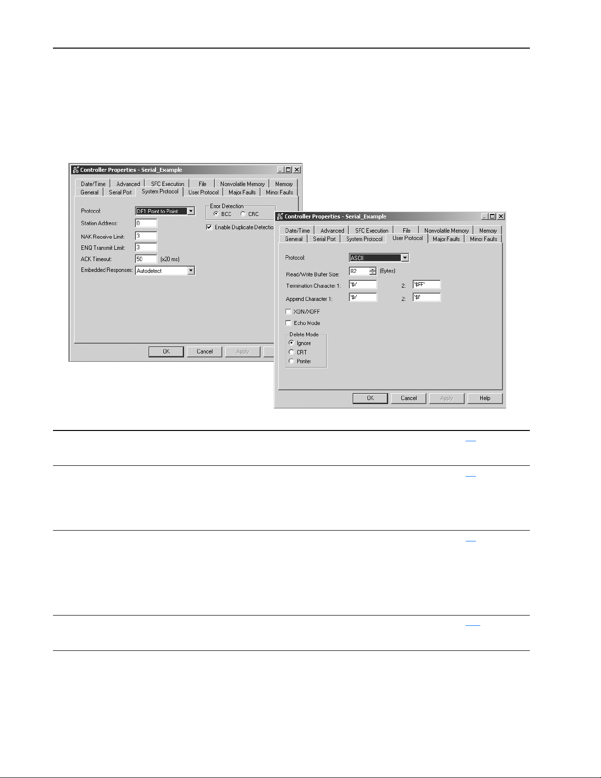
5-4 Communicating with Devices on a Serial Link
3. On the System Protocol tab, select the appropriate DF1 communication
mode for point-to-point or master/slave communications.
Or use the User Protocol tab to specify ASCII protocol to communicate to
an ASCII device.
ahw0917.tif
Use this mode: For: See page:
DF1 point-to-point communication between the controller and one other DF1-protocol-compatible device.
This is the default system mode.
This mode is typically used to program the controller through its serial port.
DF1 master mode control of polling and message transmission between the master and slave nodes.
The master/slave network includes one controller configured as the master node and as many
as 254 slave nodes. Link slave nodes using modems or line drivers.
A master/slave network can have node numbers from 0-254. Each node must have a unique
node address. Also, at least 2 nodes must exist to define your link as a network (1 master and
1 slave station are the two nodes).
DF1 slave mode using a controller as a slave station in a master/slave serial communication network.
When there are multiple slave stations on the network, link slave stations using modems or
User mode communicating with ASCII devices
line drivers. When you have a single slave station on the network, you do not need a modem
to connect the slave station to the master; you can configure the control parameters for no
handshaking. You can connect 2-255 nodes to a single link. In DF1 slave mode, a controller
uses DF1 half-duplex protocol.
One node is designated as the master and it controls who has access to the link. All the other
nodes are slave stations and must wait for permission from the master before transmitting.
This requires your program logic to use the ASCII instructions to read and write data from and
to an ASCII device.
5-6
5-9
5-8
5-12
ahw0918.tif
Important: Half-Duplex settings do not work as with other Logix
controllers. RTS and CTS are not functional.
Page 97

Configuring the Communication Driver
Use RSLinx software to configure the serial communication driver. Select
the “DF1” driver.
1. In the Communications menu, select the Configure Driver.
From the Available Driver Type list select the DF1 Driver, then click
Configure.
ahw0481.tif
Communicating with Devices on a Serial Link 5-5
2. Specify a name for the driver and click OK.
ahw0482.tif
3. Specify the appropriate communication settings.
ahw0484.tif
ahw0483.tif
Page 98

5-6 Communicating with Devices on a Serial Link
Example 1: Workstation Directly Connected to a DriveLogix Controller
In the following example, a workstation directly connects to a
DriveLogi5730 controller over a serial link. This is useful for downloading
a controller project directly to the controller.
ahw0919.eps
Use RSLogix 5000 programming software to configure the controller’s
serial port for the DF1 point-to-point (full-duplex) protocol. This type of
protocol supports simultaneous transmission between two devices in both
directions. The DF1 point-to-point protocol controls message flow, detects
and signals errors, and retries if errors are detected.
Configuring a DF1 Point-to-Point Station
This field: Description:
Station address The station address for the serial port on the DF1 point-to-point network. Enter a valid DF1 address
(0-254). Address 255 is reserved for broadcast messages. The default is 0.
NAK receive limit Specifies the number of NAKs the controller can receive in response to a message transmission.
Enter a value 0-127. The default is 3.
ENQ transmit limit Specifies the number of inquiries (ENQs) you want the controller to send after an ACK timeout.
ACK timeout Specifies the amount of time you want the controller to wait for an acknowledgment to its message
Embedded response Specifies how to enable embedded responses.
Error detection Select BCC or CRC error detection.
Enable duplicate
detection
Enter a value 0-127. The default is 3.
transmission.
Enter a value 0-32767. Limits are defined in 20ms intervals. The default is 50 (1000ms).
Select Autodetect (enabled only after receiving one embedded response) or Enabled. The default is
Autodetect.
Configure both stations to use the same type of error checking.
BCC: the controller sends and accepts messages that end with a BCC byte for error checking. BCC
is quicker and easier to implement in a computer driver. This is the default.
CRC: the controller sends and accepts messages with a 2-byte CRC for error checking. CRC is a
more complete method.
Select whether or not the controller should detect duplicate messages. The default is duplicate
detection enabled.
Page 99

Communicating with Devices on a Serial Link 5-7
Example 2: Workstation Remotely Connected to a DriveLogix Controller
In the following example, a workstation remotely connects to a DriveLogix
controller over s serial link. A modem is connected to the controller to
provide remote access.
ahw0920.eps
modem
modem
If you use a modem to remotely connect the controller to one workstation,
use RSLogix 5000 programming software to configure the serial port of the
controller for the DF1 point-to-point (full-duplex) protocol, as in the
previous example. If the controller is part of a master/slave serial network,
configure the serial port of the controller for either the DF1 master or DF1
slave protocol (both half-duplex).
Page 100

5-8 Communicating with Devices on a Serial Link
Master/Slave Communication Methods
A master station can communicate with a slave station in two ways:
Name: This method: Benefits:
standard
communication mode
message-based
communication mode
Initiates polling packets to slave stations
according to their position in the polling array(s).
Polling packets are formed based on the contents
of the normal poll array and the priority poll array.
initiates communication to slave stations using
only user-programmed message (MSG)
instructions.
Each request for data from a slave station must
be programmed via a MSG instruction.
The master polls the slave station for a reply to
the message after waiting a user-configured
period of time. The waiting period gives the slave
station time to formulate a reply and prepare the
reply for transmission. After all of the messages in
the master’s message-out queue are transmitted,
the slave-to-slave queue is checked for messages
to send.
This communication method is most often used for point-to-multipoint
configurations.
This method provides these capabilities:
• slave stations can send messages to the master station (polled
report-by-exception)
• slave stations can send messages to each other via the master
• master maintains an active station array
The poll array resides in a user-designated data file. You can configure
the master:
• to send messages during its turn in the poll array
or
• for between-station polls (master transmits any message that it
needs to send before polling the next slave station)
In either case, configure the master to receive multiple messages or a
single message per scan from each slave station.
If your application uses satellite transmission or public
switched-telephone-network transmission, consider choosing
message-based communication. Communication to a slave station
can be initiated on an as-needed basis.
Also choose this method if you need to communicate with
non-intelligent remote terminal units (RTUs).
Configuring a DF1 Slave Station
This field: Description:
Station address The station address for the serial port on the DF1 slave.
Transmit retries The number of times the remote station retries a message after the first attempt before the station declares the message
Slave poll timeout Specifies the amount of time the slave station waits to be polled by a master before indicating a fault.
EOT suppression Select whether or not to suppress sending EOT packets in response to a poll. The default is not to suppress sending
Error detection Select BCC or CRC error detection.
Enable duplicate
detection
Enter a valid DF1 address (0-254). Address 255 is reserved for broadcast messages. The default is 0.
undeliverable.
Enter a value 0-127. The default is 3.
Enter a value 0-32767. Limits are defined in 20ms intervals. The default is 3000 (60,000ms).
EOT packets.
Configure both stations to use the same type of error checking.
BCC: the controller sends and accepts messages that end with a BCC byte for error checking. BCC is quicker and
easier to implement in a computer driver. This is the default.
CRC: the controller sends and accepts messages with a 2-byte CRC for error checking. CRC is a more complete
method.
Select whether or not the controller should detect duplicate messages. The default is duplicate detection enabled.
 Loading...