

Page 1
DriveLogix System
5720
User Manual
Page 2
Important User Information
Solid state equipment has operational characteristics differing from those of
electromechanical equipment. “Safety Guidelines for the Application, Installation and
Maintenance of Solid State Controls” (Publication SGI-1.1 available from your local
Rockwell Automation Sales Office or online at http://www.ab.com/manuals/gi)
describes some important differences between solid state equipment and
hard-wired electromechanical devices. Because of this difference, and also
because of the wide variety of uses for solid state equipment, all persons
responsible for applying this equipment must satisfy themselves that each
intended application of this equipment is acceptable.
In no event will Rockwell Automation, Inc. be responsible or liable for indirect
or consequential damages resulting from the use or application of this
equipment.
The examples and diagrams in this manual are included solely for illustrative
purposes. Because of the many variables and requirements associated with any
particular installation, Rockwell Automation, Inc. cannot assume responsibility
or liability for actual use based on the examples and diagrams.
No patent liability is assumed by Rockwell Automation, Inc. with respect to
use of information, circuits, equipment, or software described in this manual.
Reproduction of the contents of this manual, in whole or in part, without
written permission of Rockwell Automation, Inc. is prohibited.
Throughout this manual we use notes to make you aware of safety
considerations.
ATTENTION
Identifies information about practices or circumstances
that can lead to personal injury or death, property damage,
or economic loss.
!
IMPORTANT
Identifies information that is critical for successful
application and understanding of the product.
Page 3

Rockwell Automation Support
Before you contact Rockwell Automation for technical assistance, we suggest
you please review the troubleshooting information contained in this
publication first.
If the problem persists, call your local distributor or contact Rockwell
Automation in one of the following ways:
Phone United
States/Canada
Outside United
States/Canada
Internet
Email
Be prepared to furnish the following information when you contact support:
• Product Catalog Number
• Product Serial Number
• Firmware Revision Level
Your Questions or Comments on this Manual
⇒
⇒
1.262.512.8176 (7 AM - 6 PM CST)
1.440.646.5800 (24 hour support)
You can access the phone number for your
country via the Internet:
1. Go to http://www.ab.com
2. Click on Support
(http://support.automation.rockwell.com)
3. Under Contact Customer Support, click on
Phone Support
Go to http://ab.com/support/abdrives
support@drives.ra.rockwell.com
If you find a problem with this manual, please notify us of it on the enclosed
How Are We Doing form.
Page 4

Page 5

Rockwell Automation Support . . . . . . . . . . . . . . . . . . . . . . . . . . . . . . . . . . . . . . . . . . . . . . . 3
Summary of Changes
Introduction . . . . . . . . . . . . . . . . . . . . . . . . . . . . . . . . . . . . . . . . . . . . . . . . . . . . . . . . . . . . . . 1
Preface
Purpose of this Manual . . . . . . . . . . . . . . . . . . . . . . . . . . . . . . . . . . . . . . . . . . . . . . . . . . . . . 1
Who Should Use This Manual . . . . . . . . . . . . . . . . . . . . . . . . . . . . . . . . . . . . . . . . . . . . . . . 2
When to Use This Manual. . . . . . . . . . . . . . . . . . . . . . . . . . . . . . . . . . . . . . . . . . . . . . . . . . . 2
How to Use this Manual . . . . . . . . . . . . . . . . . . . . . . . . . . . . . . . . . . . . . . . . . . . . . . . . . . . . 2
Controller Firmware Revision. . . . . . . . . . . . . . . . . . . . . . . . . . . . . . . . . . . . . . . . . . . . . . . . 2
Chapter 1 Getting Started
Introduction . . . . . . . . . . . . . . . . . . . . . . . . . . . . . . . . . . . . . . . . . . . . . . . . . . . . . . . . . . . . . . 1
Connecting Battery . . . . . . . . . . . . . . . . . . . . . . . . . . . . . . . . . . . . . . . . . . . . . . . . . . . . . . . . 2
Creating and Downloading a Project . . . . . . . . . . . . . . . . . . . . . . . . . . . . . . . . . . . . . . . . . . 3
Creating a project . . . . . . . . . . . . . . . . . . . . . . . . . . . . . . . . . . . . . . . . . . . . . . . . . . . . . . . . . 4
Changing project properties . . . . . . . . . . . . . . . . . . . . . . . . . . . . . . . . . . . . . . . . . . . . . . . . . 5
Configuring the host PowerFlex 700S Drive . . . . . . . . . . . . . . . . . . . . . . . . . . . . . . . . . . . . 6
Configuring the host PowerFlex 700S Drive (continued). . . . . . . . . . . . . . . . . . . . . . . . . . . 7
Adding a local input module1 . . . . . . . . . . . . . . . . . . . . . . . . . . . . . . . . . . . . . . . . . . . . . . . . 8
Adding a local input module (continued) . . . . . . . . . . . . . . . . . . . . . . . . . . . . . . . . . . . . . . . 9
Adding a local output module . . . . . . . . . . . . . . . . . . . . . . . . . . . . . . . . . . . . . . . . . . . . . . . 10
Adding a local output module (continued) . . . . . . . . . . . . . . . . . . . . . . . . . . . . . . . . . . . . . 11
Adding a local analog module. . . . . . . . . . . . . . . . . . . . . . . . . . . . . . . . . . . . . . . . . . . . . . . 12
Adding a local analog module (continued) . . . . . . . . . . . . . . . . . . . . . . . . . . . . . . . . . . . . . 13
Changing module properties . . . . . . . . . . . . . . . . . . . . . . . . . . . . . . . . . . . . . . . . . . . . . . . . 14
Viewing I/O tags . . . . . . . . . . . . . . . . . . . . . . . . . . . . . . . . . . . . . . . . . . . . . . . . . . . . . . . . . 15
Creating other tags . . . . . . . . . . . . . . . . . . . . . . . . . . . . . . . . . . . . . . . . . . . . . . . . . . . . . . . 16
Documenting I/O with alias tags. . . . . . . . . . . . . . . . . . . . . . . . . . . . . . . . . . . . . . . . . . . . . 17
Entering logic . . . . . . . . . . . . . . . . . . . . . . . . . . . . . . . . . . . . . . . . . . . . . . . . . . . . . . . . . . . 18
Entering logic (continued). . . . . . . . . . . . . . . . . . . . . . . . . . . . . . . . . . . . . . . . . . . . . . . . . . 19
Downloading a project . . . . . . . . . . . . . . . . . . . . . . . . . . . . . . . . . . . . . . . . . . . . . . . . . . . . 20
Viewing program scan time. . . . . . . . . . . . . . . . . . . . . . . . . . . . . . . . . . . . . . . . . . . . . . . . . 21
Viewing controller memory usage . . . . . . . . . . . . . . . . . . . . . . . . . . . . . . . . . . . . . . . . . . . 22
What To Do Next . . . . . . . . . . . . . . . . . . . . . . . . . . . . . . . . . . . . . . . . . . . . . . . . . . . . . . . . 22
Table of Contents
Chapter 2 What Is DriveLogix?
Using This Chapter . . . . . . . . . . . . . . . . . . . . . . . . . . . . . . . . . . . . . . . . . . . . . . . . . . . . . . . . 1
Developing programs . . . . . . . . . . . . . . . . . . . . . . . . . . . . . . . . . . . . . . . . . . . . . . . . . . . . . . 2
Using the Event Task. . . . . . . . . . . . . . . . . . . . . . . . . . . . . . . . . . . . . . . . . . . . . . . . . . . . . . . 6
How the DriveLogix System Uses Connections . . . . . . . . . . . . . . . . . . . . . . . . . . . . . . . . . . 9
Determining Connections for Produced and Consumed Tags . . . . . . . . . . . . . . . . . . . . . . 10
Determining Connections for Messages . . . . . . . . . . . . . . . . . . . . . . . . . . . . . . . . . . . . . . . 11
Determining Connections for I/O Modules . . . . . . . . . . . . . . . . . . . . . . . . . . . . . . . . . . . . 12
Determining Total Connection Requirements. . . . . . . . . . . . . . . . . . . . . . . . . . . . . . . . . . . 17
Downloading Projects . . . . . . . . . . . . . . . . . . . . . . . . . . . . . . . . . . . . . . . . . . . . . . . . . . . . . 20
Selecting a System Overhead Percentage . . . . . . . . . . . . . . . . . . . . . . . . . . . . . . . . . . . . . . 22
Page 6

2 Table of Contents
Chapter 3 Placing and Configuring the Drive
Using This Chapter . . . . . . . . . . . . . . . . . . . . . . . . . . . . . . . . . . . . . . . . . . . . . . . . . . . . . . . . 1
Understanding the Interface to the Drive. . . . . . . . . . . . . . . . . . . . . . . . . . . . . . . . . . . . . . . . 1
Determining When the Controller Updates the Drive . . . . . . . . . . . . . . . . . . . . . . . . . . . . . . 3
Placing and Configuring the Drive . . . . . . . . . . . . . . . . . . . . . . . . . . . . . . . . . . . . . . . . . . . . 4
Inhibiting the Drive Connection . . . . . . . . . . . . . . . . . . . . . . . . . . . . . . . . . . . . . . . . . . . . . 13
Using DriveExecutive Lite. . . . . . . . . . . . . . . . . . . . . . . . . . . . . . . . . . . . . . . . . . . . . . . . . . 15
Accessing Drive Data . . . . . . . . . . . . . . . . . . . . . . . . . . . . . . . . . . . . . . . . . . . . . . . . . . . . . 23
Monitoring Drive Data. . . . . . . . . . . . . . . . . . . . . . . . . . . . . . . . . . . . . . . . . . . . . . . . . . . . . 23
Chapter 4 Placing and Configuring Local I/O
Using This Chapter . . . . . . . . . . . . . . . . . . . . . . . . . . . . . . . . . . . . . . . . . . . . . . . . . . . . . . . . 1
Placing Local I/O Modules . . . . . . . . . . . . . . . . . . . . . . . . . . . . . . . . . . . . . . . . . . . . . . . . . . 2
Determining When the Controller Updates I/O. . . . . . . . . . . . . . . . . . . . . . . . . . . . . . . . . . . 3
Configuring a DIN Rail . . . . . . . . . . . . . . . . . . . . . . . . . . . . . . . . . . . . . . . . . . . . . . . . . . . . . 5
Configuring Local I/O Modules . . . . . . . . . . . . . . . . . . . . . . . . . . . . . . . . . . . . . . . . . . . . . . 6
Inhibiting I/O Module Operation. . . . . . . . . . . . . . . . . . . . . . . . . . . . . . . . . . . . . . . . . . . . . 10
Accessing I/O Data . . . . . . . . . . . . . . . . . . . . . . . . . . . . . . . . . . . . . . . . . . . . . . . . . . . . . . . 13
Monitoring I/O Modules . . . . . . . . . . . . . . . . . . . . . . . . . . . . . . . . . . . . . . . . . . . . . . . . . . . 16
Chapter5 Configuring DriveLogix Motion
Using This Chapter . . . . . . . . . . . . . . . . . . . . . . . . . . . . . . . . . . . . . . . . . . . . . . . . . . . . . . . . 1
Configuring the Drive . . . . . . . . . . . . . . . . . . . . . . . . . . . . . . . . . . . . . . . . . . . . . . . . . . . . . . 2
Programming the Controller . . . . . . . . . . . . . . . . . . . . . . . . . . . . . . . . . . . . . . . . . . . . . . . . . 5
Supported Motion Commands . . . . . . . . . . . . . . . . . . . . . . . . . . . . . . . . . . . . . . . . . . . . . . 12
Chapter 6 Communicating with Devices on an EtherNet/IP Link
Using This Chapter . . . . . . . . . . . . . . . . . . . . . . . . . . . . . . . . . . . . . . . . . . . . . . . . . . . . . . . . 1
Configuring Your System for a EtherNet/IP Link . . . . . . . . . . . . . . . . . . . . . . . . . . . . . . . . . 1
Configuring Remote I/O . . . . . . . . . . . . . . . . . . . . . . . . . . . . . . . . . . . . . . . . . . . . . . . . . . . . 8
Sending Messages . . . . . . . . . . . . . . . . . . . . . . . . . . . . . . . . . . . . . . . . . . . . . . . . . . . . . . . . 13
Producing and Consuming Data . . . . . . . . . . . . . . . . . . . . . . . . . . . . . . . . . . . . . . . . . . . . . 20
Guidelines for Configuring Connections. . . . . . . . . . . . . . . . . . . . . . . . . . . . . . . . . . . . . . . 23
Example 1: DriveLogix Controller and Remote I/O . . . . . . . . . . . . . . . . . . . . . . . . . . . . . . 23
Example 2: DriveLogix Controller to DriveLogix Controller. . . . . . . . . . . . . . . . . . . . . . . 25
Example 3: DriveLogix Controller to Other Devices . . . . . . . . . . . . . . . . . . . . . . . . . . . . . 29
Chapter 7 Communicating with Devices on a ControlNet Link
Using This Chapter . . . . . . . . . . . . . . . . . . . . . . . . . . . . . . . . . . . . . . . . . . . . . . . . . . . . . . . . 1
Configuring Your System for a ControlNet Link . . . . . . . . . . . . . . . . . . . . . . . . . . . . . . . . . 1
Configuring Remote I/O . . . . . . . . . . . . . . . . . . . . . . . . . . . . . . . . . . . . . . . . . . . . . . . . . . . . 5
Scheduling the ControlNet Network . . . . . . . . . . . . . . . . . . . . . . . . . . . . . . . . . . . . . . . . . . 10
Sending Messages . . . . . . . . . . . . . . . . . . . . . . . . . . . . . . . . . . . . . . . . . . . . . . . . . . . . . . . . 11
Producing and Consuming Data . . . . . . . . . . . . . . . . . . . . . . . . . . . . . . . . . . . . . . . . . . . . . 17
Guidelines for Configuring Connections. . . . . . . . . . . . . . . . . . . . . . . . . . . . . . . . . . . . . . . 21
Example 1: DriveLogix Controller and Remote I/O . . . . . . . . . . . . . . . . . . . . . . . . . . . . . . 22
Example 2: DriveLogix Controller to DriveLogix Controller. . . . . . . . . . . . . . . . . . . . . . . 24
Example 3: DriveLogix Controller to Other Devices . . . . . . . . . . . . . . . . . . . . . . . . . . . . . 28
Page 7

Chapter 8 Communicating with Devices on a DeviceNet Link
Using This Chapter . . . . . . . . . . . . . . . . . . . . . . . . . . . . . . . . . . . . . . . . . . . . . . . . . . . . . . . . 1
Configuring Your System for a DeviceNet Link. . . . . . . . . . . . . . . . . . . . . . . . . . . . . . . . . . 1
Placing DeviceNet Devices. . . . . . . . . . . . . . . . . . . . . . . . . . . . . . . . . . . . . . . . . . . . . . . . . . 5
Accessing DeviceNet Devices. . . . . . . . . . . . . . . . . . . . . . . . . . . . . . . . . . . . . . . . . . . . . . . . 6
Placing the Communication Card in Run Mode . . . . . . . . . . . . . . . . . . . . . . . . . . . . . . . . . . 9
Example 1: DriveLogix Controller and DeviceNet Devices. . . . . . . . . . . . . . . . . . . . . . . . 10
Example 2: Using a 1788-CN2DN Linking Device . . . . . . . . . . . . . . . . . . . . . . . . . . . . . . 11
Chapter 9 Communicating with Devices on a Serial Link
Using This Chapter . . . . . . . . . . . . . . . . . . . . . . . . . . . . . . . . . . . . . . . . . . . . . . . . . . . . . . . . 1
Configuring Your System for a Serial Link . . . . . . . . . . . . . . . . . . . . . . . . . . . . . . . . . . . . . 1
Example 1: Workstation Directly Connected to a DriveLogix Controller . . . . . . . . . . . . . . 8
Example 2: Workstation Remotely Connected to a DriveLogix Controller . . . . . . . . . . . . . 9
Example 3: DriveLogix Controller to a Bar Code Reader . . . . . . . . . . . . . . . . . . . . . . . . . 14
Chapter 10 Communicating with Devices on a DH-485 Link
Using This Chapter . . . . . . . . . . . . . . . . . . . . . . . . . . . . . . . . . . . . . . . . . . . . . . . . . . . . . . . . 1
Configuring Your System for a DH-485 Link. . . . . . . . . . . . . . . . . . . . . . . . . . . . . . . . . . . . 1
Planning a DH-485 Network. . . . . . . . . . . . . . . . . . . . . . . . . . . . . . . . . . . . . . . . . . . . . . . . . 4
Installing a DH-485 Network . . . . . . . . . . . . . . . . . . . . . . . . . . . . . . . . . . . . . . . . . . . . . . . . 6
Example: DriveLogix Controller, ControlLogix Controller, and SLC Controller on the Same
DH-485 Network. . . . . . . . . . . . . . . . . . . . . . . . . . . . . . . . . . . . . . . . . . . . . . . . . . . . . . . . . . 9
Table of Contents 3
Chapter11 Communicating with Devices on a Third-Party Link
Chapter12 DriveLogix Back-Up on DeviceNet
Appendix A DriveLogix System Specifications
Appendix B Installing and Maintaining the Battery
Using This Chapter . . . . . . . . . . . . . . . . . . . . . . . . . . . . . . . . . . . . . . . . . . . . . . . . . . . . . . . . 1
Configuring Your System for a Third-Party Link . . . . . . . . . . . . . . . . . . . . . . . . . . . . . . . . . 1
Using This Chapter . . . . . . . . . . . . . . . . . . . . . . . . . . . . . . . . . . . . . . . . . . . . . . . . . . . . . . . . 1
How the Back-up Works . . . . . . . . . . . . . . . . . . . . . . . . . . . . . . . . . . . . . . . . . . . . . . . . . . . . 2
Power-Up and System Start-up. . . . . . . . . . . . . . . . . . . . . . . . . . . . . . . . . . . . . . . . . . . . . . . 4
Developing the DriveLogix Back-Up Application . . . . . . . . . . . . . . . . . . . . . . . . . . . . . . . . 6
Using Indicators to Check Status . . . . . . . . . . . . . . . . . . . . . . . . . . . . . . . . . . . . . . . . . . . . 13
Development and Debugging Tips . . . . . . . . . . . . . . . . . . . . . . . . . . . . . . . . . . . . . . . . . . . 13
Using This Appendix . . . . . . . . . . . . . . . . . . . . . . . . . . . . . . . . . . . . . . . . . . . . . . . . . . . . . . 1
DriveLogix Controller. . . . . . . . . . . . . . . . . . . . . . . . . . . . . . . . . . . . . . . . . . . . . . . . . . . . . . 1
1756-BA1 Battery . . . . . . . . . . . . . . . . . . . . . . . . . . . . . . . . . . . . . . . . . . . . . . . . . . . . . . . . . 3
DriveLogix Controller Serial Cables. . . . . . . . . . . . . . . . . . . . . . . . . . . . . . . . . . . . . . . . . . . 4
DriveLogix Controller LEDs. . . . . . . . . . . . . . . . . . . . . . . . . . . . . . . . . . . . . . . . . . . . . . . . . 6
Using this Appendix . . . . . . . . . . . . . . . . . . . . . . . . . . . . . . . . . . . . . . . . . . . . . . . . . . . . . . . 1
Connecting the Battery . . . . . . . . . . . . . . . . . . . . . . . . . . . . . . . . . . . . . . . . . . . . . . . . . . . . . 1
Storing Replacement Batteries . . . . . . . . . . . . . . . . . . . . . . . . . . . . . . . . . . . . . . . . . . . . . . . 2
Estimating Battery Life . . . . . . . . . . . . . . . . . . . . . . . . . . . . . . . . . . . . . . . . . . . . . . . . . . . . . 2
Replacing a Battery . . . . . . . . . . . . . . . . . . . . . . . . . . . . . . . . . . . . . . . . . . . . . . . . . . . . . . . . 3
Page 8

4 Table of Contents
Appendix C Access Procedures
Using this Appendix . . . . . . . . . . . . . . . . . . . . . . . . . . . . . . . . . . . . . . . . . . . . . . . . . . . . . . . 1
Removing Cover(s) . . . . . . . . . . . . . . . . . . . . . . . . . . . . . . . . . . . . . . . . . . . . . . . . . . . . . . . . 2
Removing Cover (For High Power Drives) . . . . . . . . . . . . . . . . . . . . . . . . . . . . . . . . . . . . . . 3
Replacing Cover(s) . . . . . . . . . . . . . . . . . . . . . . . . . . . . . . . . . . . . . . . . . . . . . . . . . . . . . . . . 4
Replacing Cover(s) Continued. . . . . . . . . . . . . . . . . . . . . . . . . . . . . . . . . . . . . . . . . . . . . . . . 5
Replacing Cover (For High Power Drives) . . . . . . . . . . . . . . . . . . . . . . . . . . . . . . . . . . . . . . 6
Index
Page 9

Summary of Changes
Introduction
This version of the DriveLogix System User Manual corresponds to version 11
and later of the controller firmware. Changes made to this manual include:
For this updated information: See:
Using the Event Task 2-6
How the DriveLogix System Uses Connections 2-9
Determining Connections for Produced and Consumed Tags 2-10
Determining Connections for Messages 2-11
Determining Connections for I/O Modules 2-12
Configuring DriveLogix Motion 5-1
Communicating with Devices on a Third-Party Link 11-1
DriveLogix Back-Up on DeviceNet 12-1
Access Procedures C-1
1 Publication 20D-UM002C-EN-P - November 2003
Page 10

2
Notes:
Publication 20D-UM002C-EN-P - November 2003
Page 11

Preface
Purpose of this Manual
This manual guides the development of projects for DriveLogix controllers. It
provides procedures on how to establish communications:
• over the following networks
– ControlNet
– DeviceNet
– serial
• with the following devices
– PowerFlex
– controllers
– I/O
– workstations
– PanelView terminals
This manual works together with the Logix5000 Controllers Common Procedures
Programming Manual, publication 1756-PM001, which covers the following
tasks:
• Manage project files
• Organize your logic
• Organize tags
• Program routines
• Test a project
• Handle faults
®
700S drive
This manual works together with the Logix Controller Motion Instruction Set,
publication 1756-RM007D, which covers the following aspects of Logix
Motion commands:
• Instruction Names
• Operands
• Structured Text
• Motion Instruction Structure
• Fault Conditions
• Execution
• Error Codes
• Status Bits
1 Publication 20D-UM002C-EN-P - November 2003
Page 12

2
Who Should Use This Manual
When to Use This Manual
How to Use this Manual
This manual is intended for those individuals who program applications that
use DriveLogix controllers, such as:
• software engineers
• control engineers
• application engineers
• instrumentation technicians
Use this manual:
• when you are ready to integrate your application with the PowerFlex
700S drive, I/0 devices, controllers, and networks in your system.
• after you perform these actions:
– develop the basic code for your application
– perform isolated tests of your application
This manual is divided into the basic tasks that you perform while
programming a DriveLogix controller. Each chapter covers a main task, such
as communicating over a specific network. For each main task, the chapter:
• lists what you need
• describes the steps to follow to accomplish that task
• provides details for each step, as necessary
• includes example system configurations
Controller Firmware Revision
This revision of the DriveLogix User Manual corresponds to the following:
• version 12 and later of the controller firmware
• version 12 of RSLogix 5000 programming software
• version 2.02 of DriveExecutive programming software
Publication 20D-UM002C-EN-P - November 2003
Page 13
Getting Started
Chapter
1
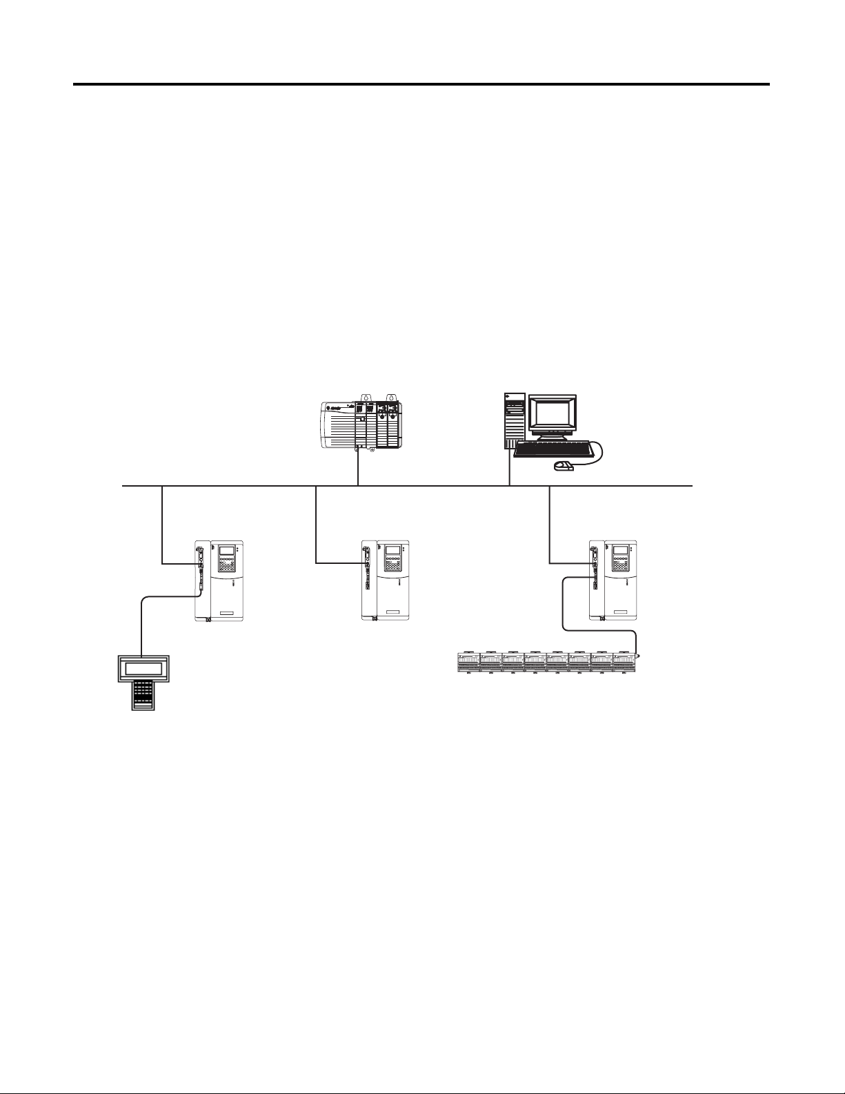
Introduction
ControlLogix controller acting as
centralized controller
DriveLogix controller using an
RS-232 connection
This chapter introduces the DriveLogix controller and provides a quick
overview on creating and downloading a project. The steps in this chapter
introduce the basic aspects of the DriveLogix controller.
The DriveLogix controller offers state-of-art control, communications, and
I/O elements in a embedded control package.
remote workstation
DriveLogix controller using local I/O
DriveLogix controllers, each with a 1788-CNC, -CNCR card,
linked over ControlNet link
This example DriveLogix system demonstrates:
• Centralized control using a ControlLogix™ controller to coordinate
several DriveLogix controllers.
• Distributed control using DriveLogix controllers at several locations.
• DriveLogix controller controlling a maximum of 8 local I/O modules.
• Local RS-232 connection for remote upload/download of a controller
project, for DF1 master/slave communications, or for ASCII
programming.
• Networked DriveLogix controllers using 1788-CNC, -CNCR
communication daugthercards to connect ControlNet links.
• Remote programming over ControlNet and EtherNet/IP.
1 Publication 20D-UM002C-EN-P - November 2003
Page 14

1-2 Getting Started
Connecting Battery
Allen-Bradley ships the DriveLogix controller with the battery installed, but
disconnected. You must connect the battary while installing the drive. Refer
to Installing and Maintaining the Battery on page B-1 and Access Procedures
on page C-1.
Publication 20D-UM002C-EN-P - November 2003
Page 15
Getting Started 1-3
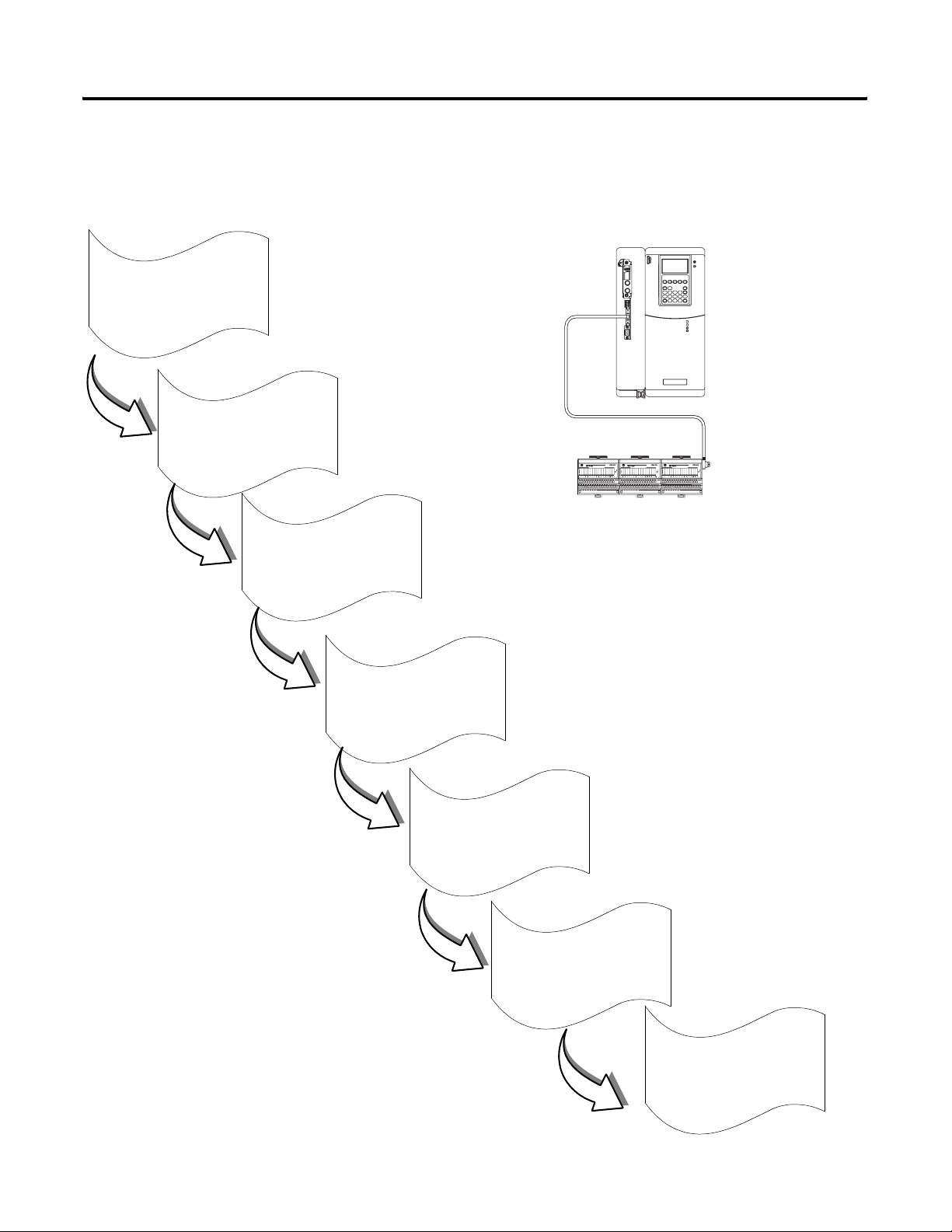
Creating and Downloading a Project
Create a project
1
go to page 1-4
Configure
PowerFlex 700S Drive
2
3
4
The following diagram illustrates the steps you follow to create and download
a project. The remainder of this chapter provides examples of each step.
System setup for this quick start:
Local
slot 0 1794-IB16
You need:
Configure
I/O modules
Create tags
• RSLogix 5000 programming software
• RSLinx communication software
• DF1 point-to-point, serial connection from the workstation
to the controller (using 1756-CP3 or 1747-CP3 cable)
If you don’t have this hardware, you can still follow these steps.
Substitute the I/O modules you have for the ones listed here and
make the appropriate changes.
Enter logic
5
Download
a project
6
View status
7
Publication 20D-UM002C-EN-P - November 2003
Page 16
1-4 Getting Started
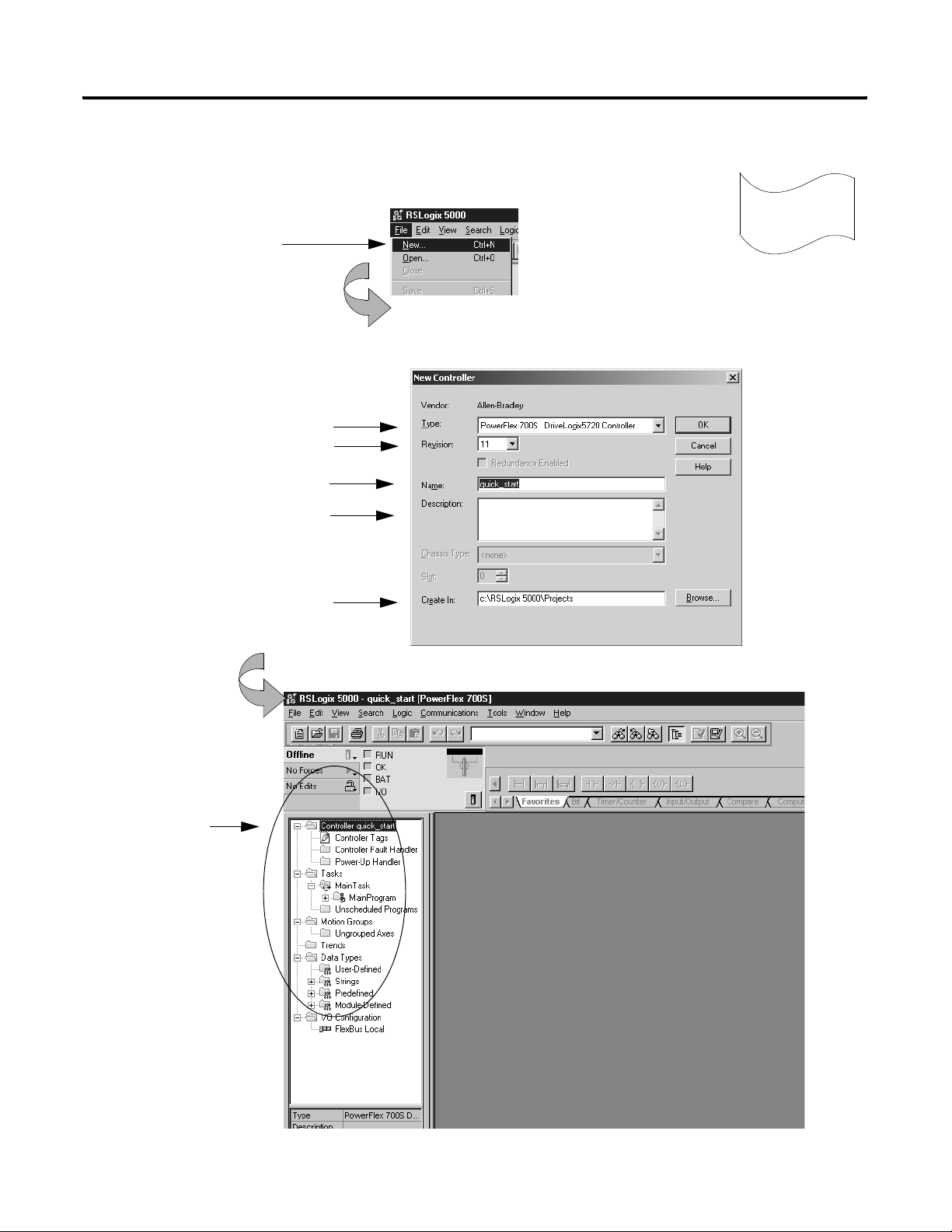
Creating a project
1. Select File → New.
2. Define the project. The software uses the project name you enter with an .ACD extension to store your project.
Select a controller type.
Select the controller revision.
Name the project.
Describe the project (optional).
Create a project
1
Select where to store the project
(typically use the default directory).
The software creates the
new controller and displays:
controller organizer
Click OK.
Publication 20D-UM002C-EN-P - November 2003
Page 17
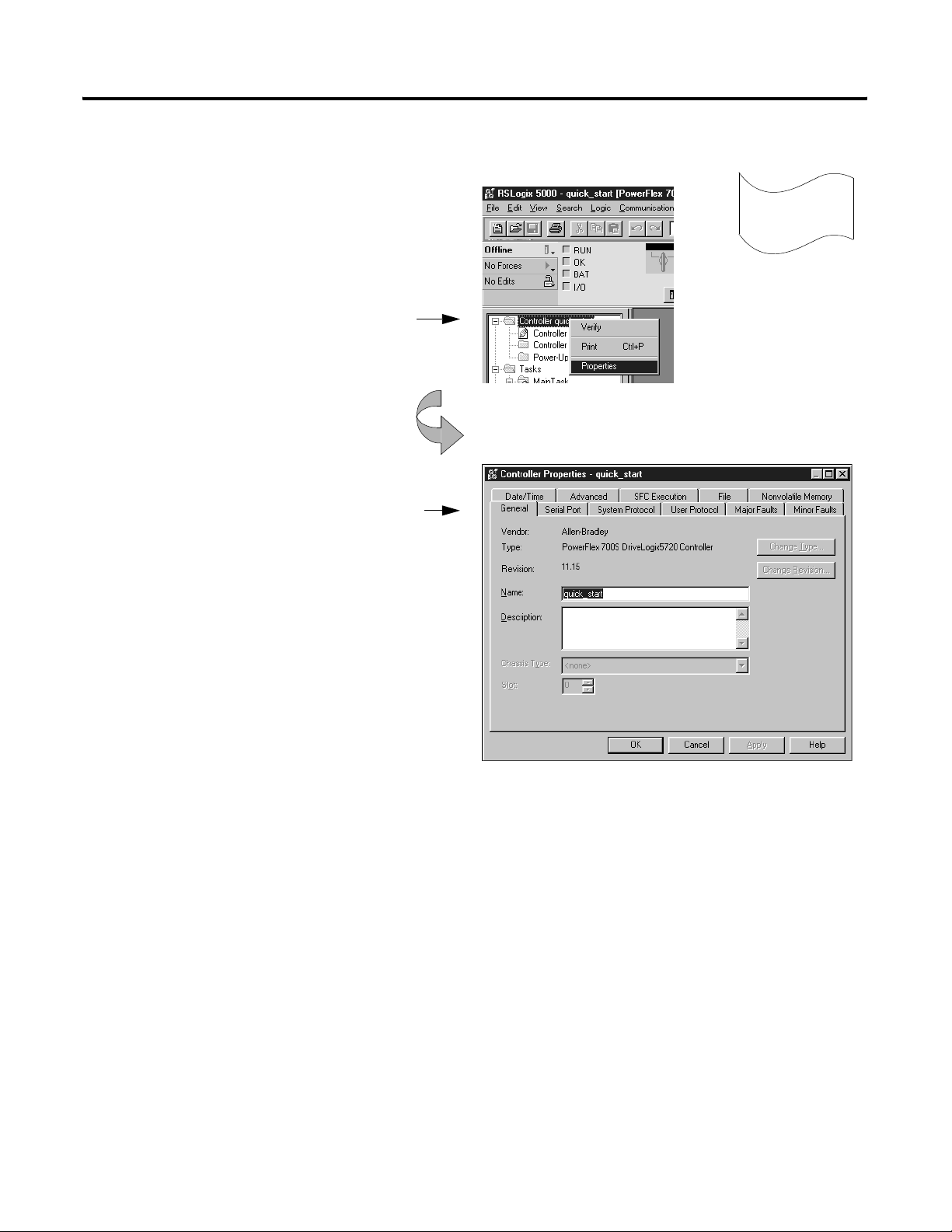
Changing project properties
1. View properties for Controller quick_start.
A. Place the cursor over the Controller quick_start folder.
B. Click the right mouse button and select Properties.
2. View the General tab.
The screen defaults to the General tab.
Verify that the controller settings are
correct. Make changes if necessary.
Getting Started 1-5
Create a project
1
Click OK.
Publication 20D-UM002C-EN-P - November 2003
Page 18
1-6 Getting Started
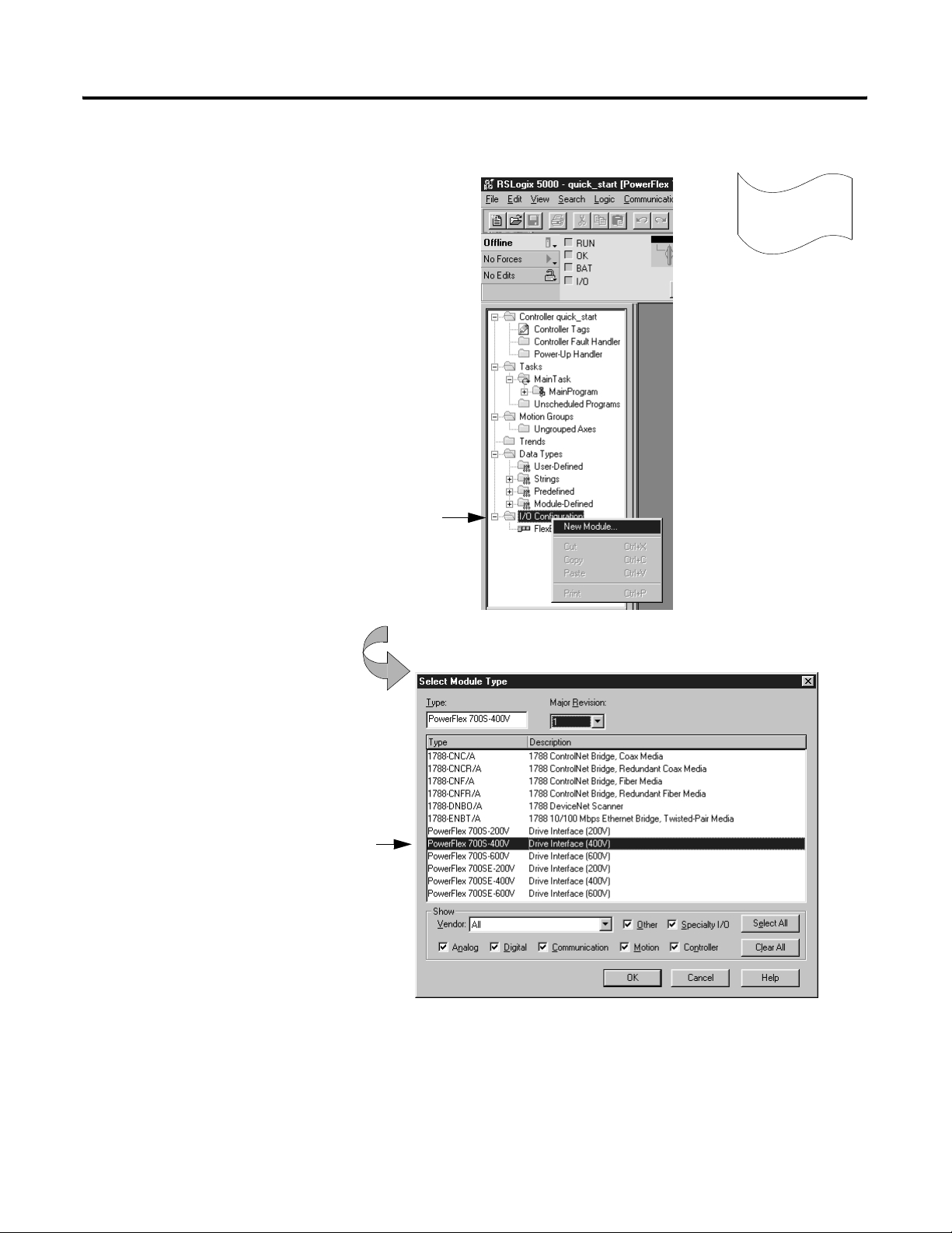
Configuring the host PowerFlex 700S Drive
1. Create the PowerFlex 700S Drive module.
Refer to Chater 3, "Placing and Configuring the
Drive" for more detailed information.
A. Place the cursor over the I/O Configuation folder.
2
Configure
B. Click the right mouse button and select New Module.
2. Select the Drive module.
Select the correct drive type.
Publication 20D-UM002C-EN-P - November 2003
Click the OK button
Page 19
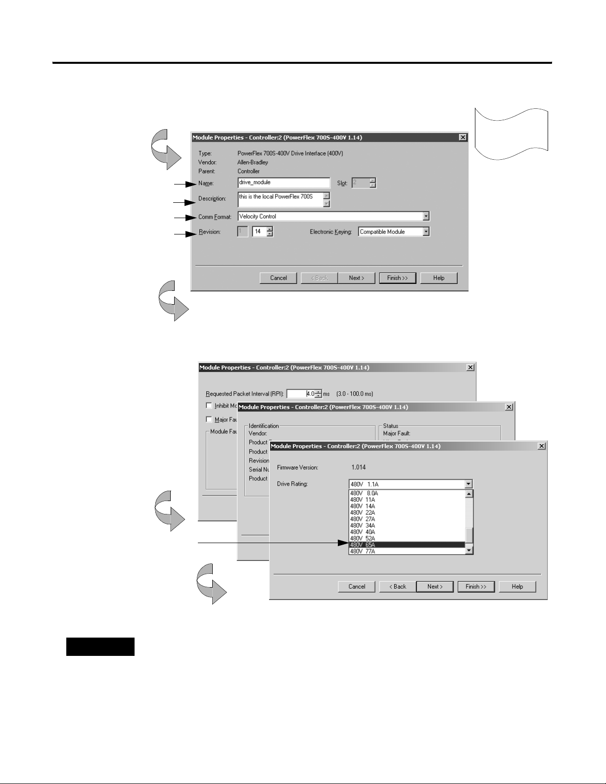
Configuring the host PowerFlex 700S Drive (continued)
3. Identify the drive module.
You should enter a name.
Describe the module (optional).
Select the communication format.
Select the minor revision and
Specify electronic keying.
Click Next
Getting Started 1-7
2
Configure
4. Use the Create wizard to configure the drive module.
Click Next
Choose the correct drive rating from the
pull-down menu
Click Next
Use default values for this example.
If you do not want to go through each screen in the Create wizard, click Finish
Click on Finish to apply and save the changes.
TIP
If no drive ratings appear, download and install DriveExecutive™ Database files from:
http://www.ab.com/drives/data.html
Publication 20D-UM002C-EN-P - November 2003
Page 20
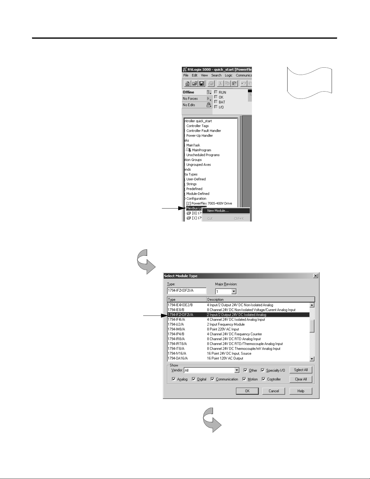
1-8 Getting Started
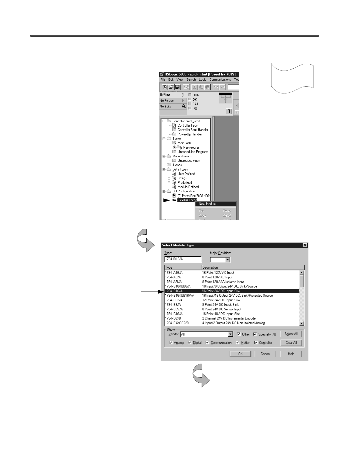
Adding a local input module1
1. Create a new module.
Refer to Chater 4, "Placing and Configuring Local I/O"
for more detailed information.
A. Place the cursor over the local DIN rail (FlexBus Local).
3
Configure
B. Click the right mouse button and select New Module.
2. Select an input module to add.
Select a catalog number.
Click OK.
Publication 20D-UM002C-EN-P - November 2003
continued
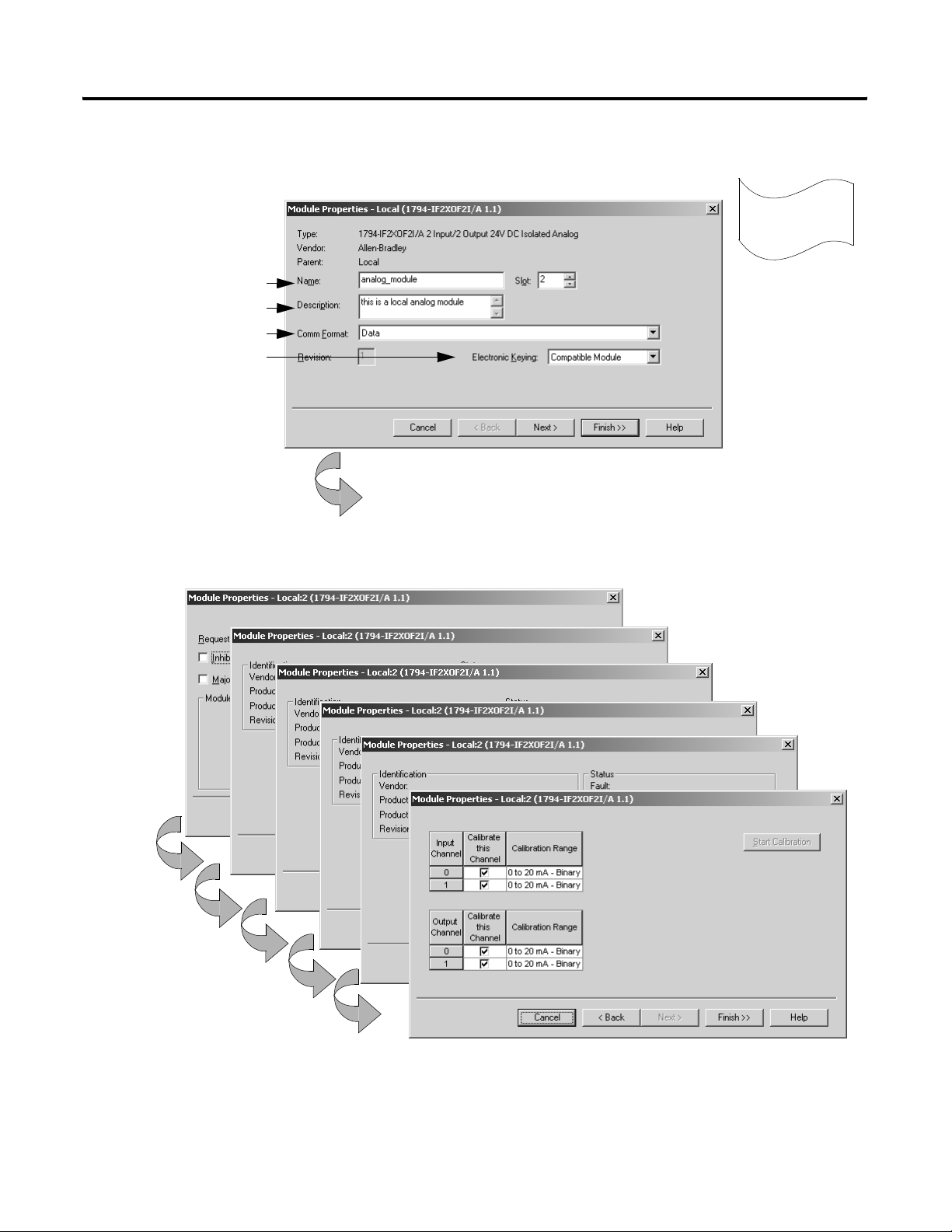
Page 21
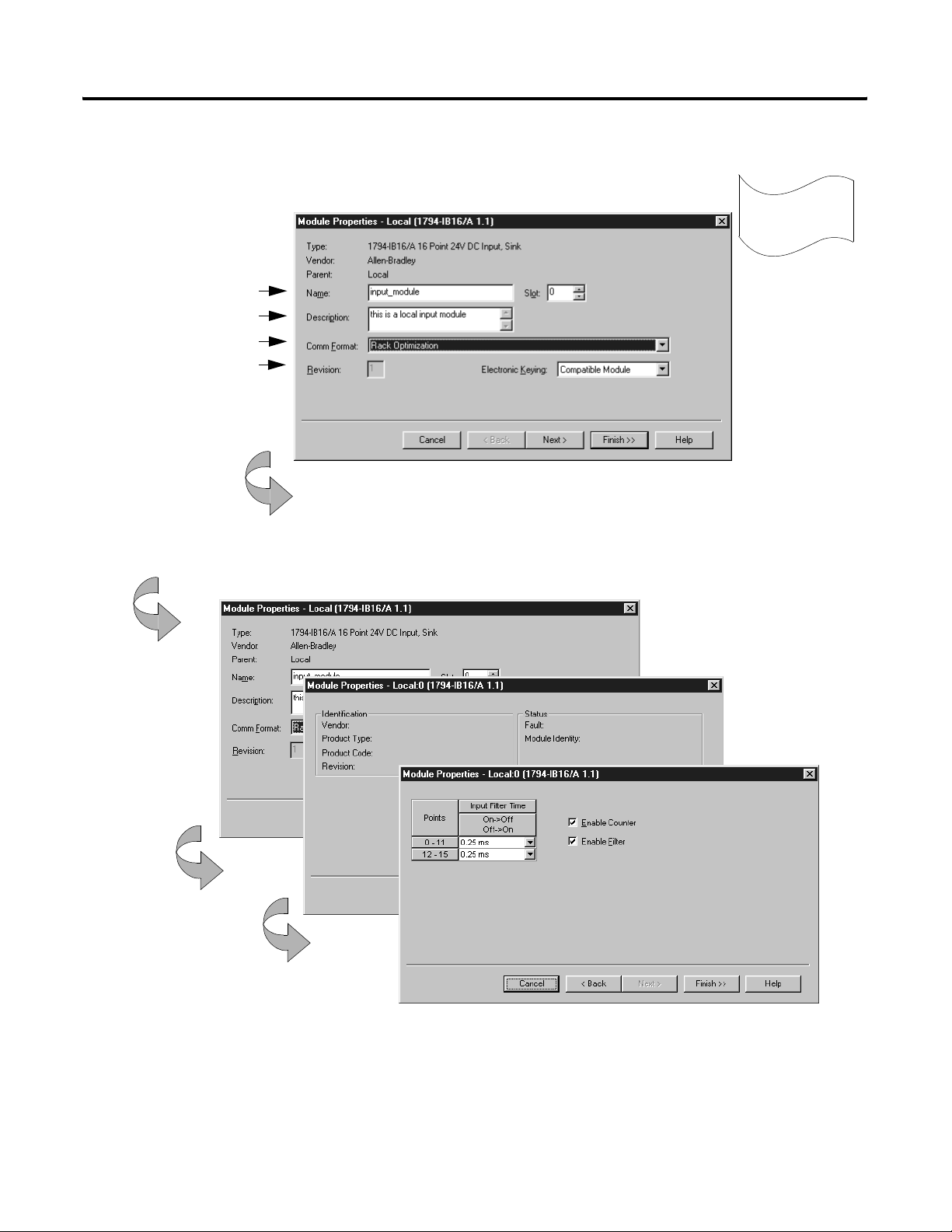
Adding a local input module (continued)
3. Identify the input module.
You should enter a name.
Describe the module (optional).
Select the communication format.
Specify electronic keying.
Click Next
These screens are specific to the 1794-IB16 input module.
Getting Started 1-9
3
Configure
4. Use the Create wizard to configure the input module.
Click Next.
Use default values for this example.
If you do not want to go through each screen in the Create wizard, click Finish
Click Finish.
Publication 20D-UM002C-EN-P - November 2003
Page 22
1-10 Getting Started
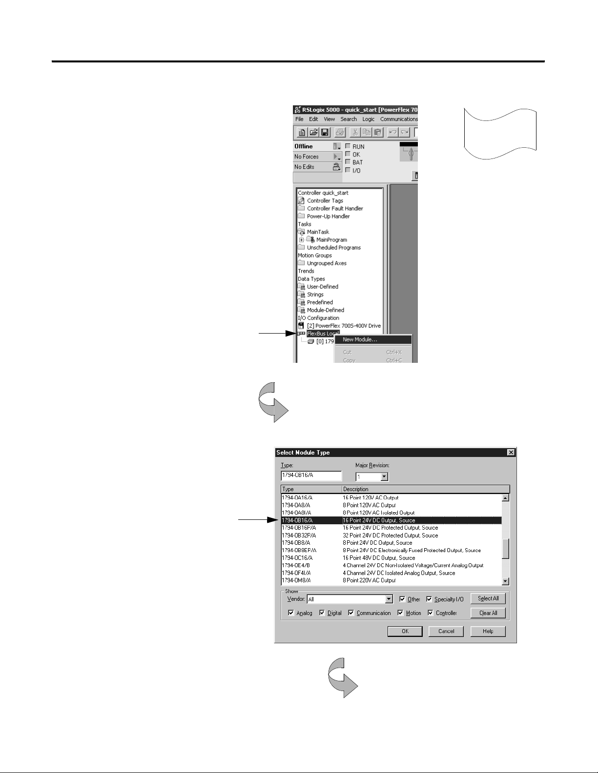
Adding a local output module
1. Create a new module.
A. Place the cursor over the local DIN rail (FlexBus Local)
3
Configure
B. Click the right mouse button and select New Module.
2. Select an output module to add.
Select a catalog number.
Publication 20D-UM002C-EN-P - November 2003
Click OK.
continued
Page 23
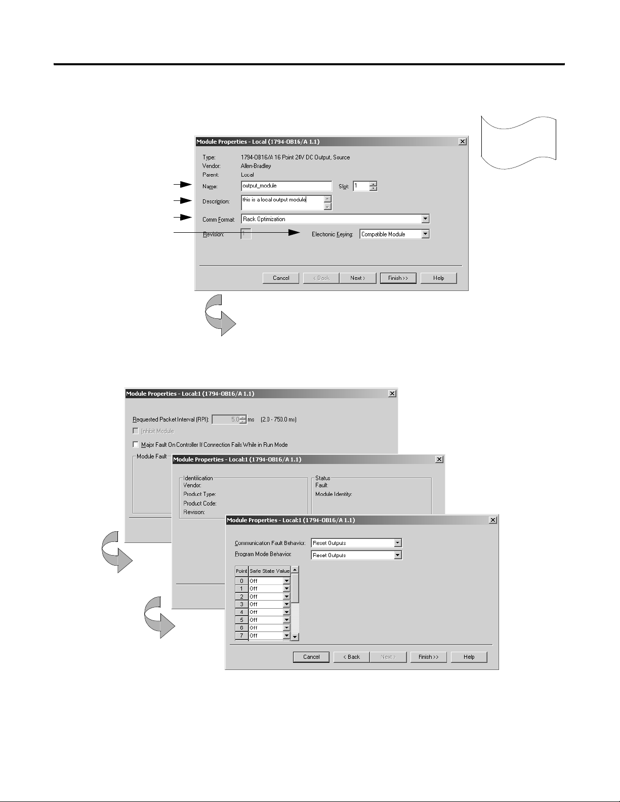
Adding a local output module (continued)
Getting Started 1-11
3. Identify the output module.
You should enter a name.
Describe the module (optional).
Select the communication format.
Specify electronic keying.
4. Use the Create wizard to configure the output module.
These screens are specific to the 1794-OB16 output module.
Click Next.
3
Use default values for this example.
If you do not want to go through each screen in the Create wizard, click
Configure
Click Next.
Click Finish.
Publication 20D-UM002C-EN-P - November 2003
Page 24
1-12 Getting Started
Adding a local analog module
1. Create a new module.
A. Place the cursor over the local DIN rail (FlexBus Local)
3
Configure
B. Click the right mouse button and select New Module.
2. Select an output module to add.
Select a catalog number.
For this quick start example, select
Publication 20D-UM002C-EN-P - November 2003
Click OK.
continued
Page 25
Adding a local analog module (continued)
Getting Started 1-13
3. Identify the output module.
You should enter a name.
Describe the module (optional).
Select the communication format.
Specify electronic keying.
4. Use the Create wizard to configure the output module.
These screens are specific to the 1794-OB16 output module.
Click Next.
3
Use default values for this example.
If you do not want to go through each screen in the Create wizard, click
Configure
Click Next.
Click Finish.
Publication 20D-UM002C-EN-P - November 2003
Page 26
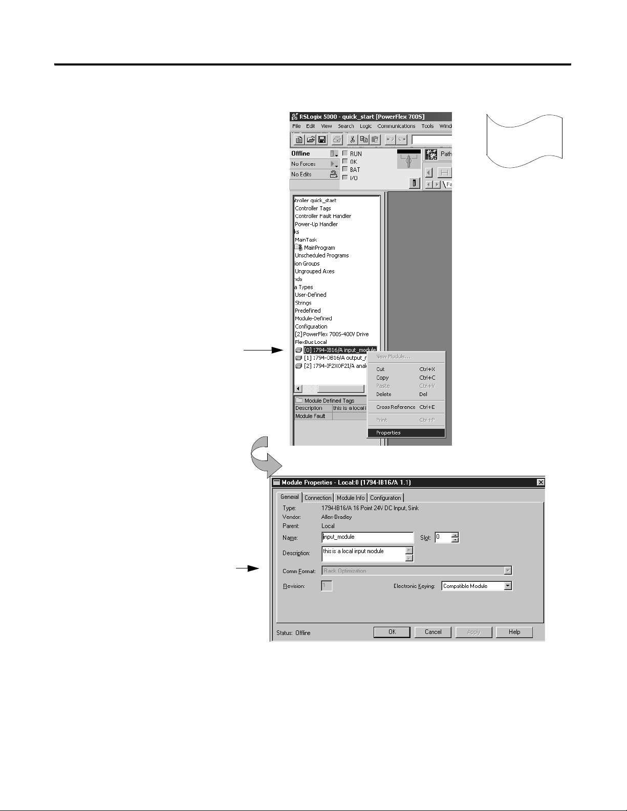
1-14 Getting Started
Changing module properties
1. View properties for the module.
A. Place the cursor over the 1794-IB16 module.
3
Configure
B. Click the right mouse button and select Properties.
2. View the General tab.
The screen defaults to the General tab.
Verify that the module settings are
correct. Make changes if necessary.
Click OK.
The tabs that appear depend on the type of module.
Publication 20D-UM002C-EN-P - November 2003
Important: If you want to change the communication format of a module, you must
Page 27
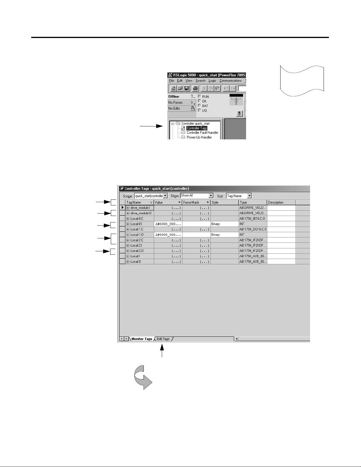
Viewing I/O tags
1. View the tags for the controller.
Place the cursor on the Controller Tags folder and
double-click.
The software displays the module-defined tags for the I/O modules you created.
PowerFlex 700S tags
Getting Started 1-15
3
Configure
1794-IB16 module tags
1794-OB16 module tags
1794-IF2XOF2I module tags
Local rail tags
Click the Edit Tags tab.
Publication 20D-UM002C-EN-P - November 2003
Page 28
1-16 Getting Started
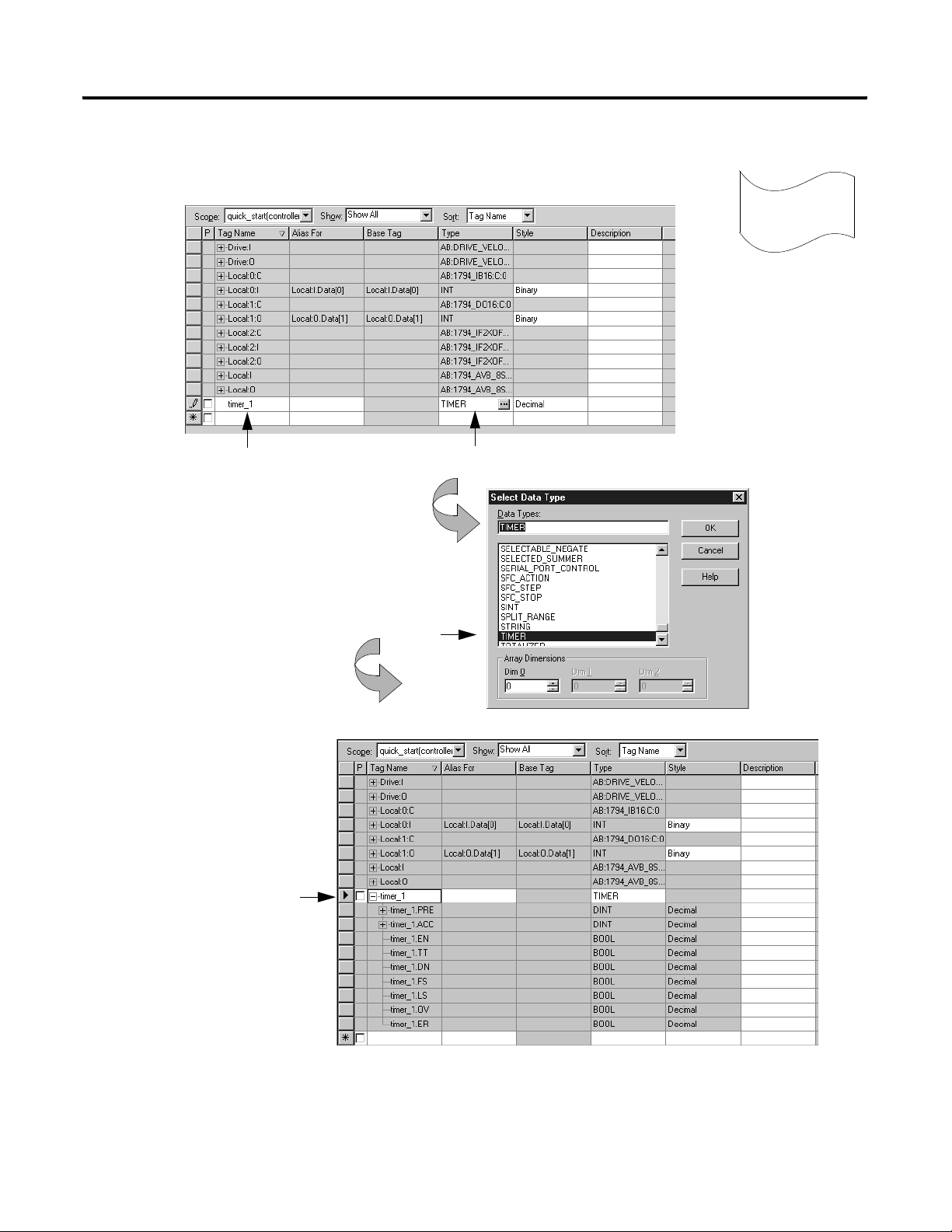
Creating other tags
1. Create a tag.
4
Create tags
Enter the name of the new tag.
2. Select the data type.
Click + to display the members
of the TIMER structure.
Tab to this column and select the data type.
Select TIMER.
Click OK.
The software displays the tag.
You might have to resize the column to see the tag extensions.
Publication 20D-UM002C-EN-P - November 2003
continued
Page 29
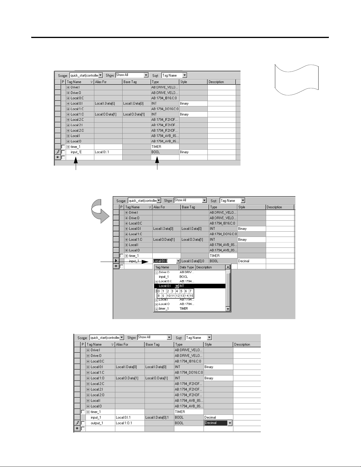
Documenting I/O with alias tags
1. Create an alias tag input_1 for Local:0:I.Data.1.
Getting Started 1-17
Create tags
4
Enter the name of the tag.
2. Select an input data word.
Tab here or click in the box.
Click here to display a grid of
bits and select the input bit.
3. Repeat steps 1 and 2 above to create an alias tag output_1 for Local:1:O.Data.1
Publication 20D-UM002C-EN-P - November 2003
Page 30
1-18 Getting Started
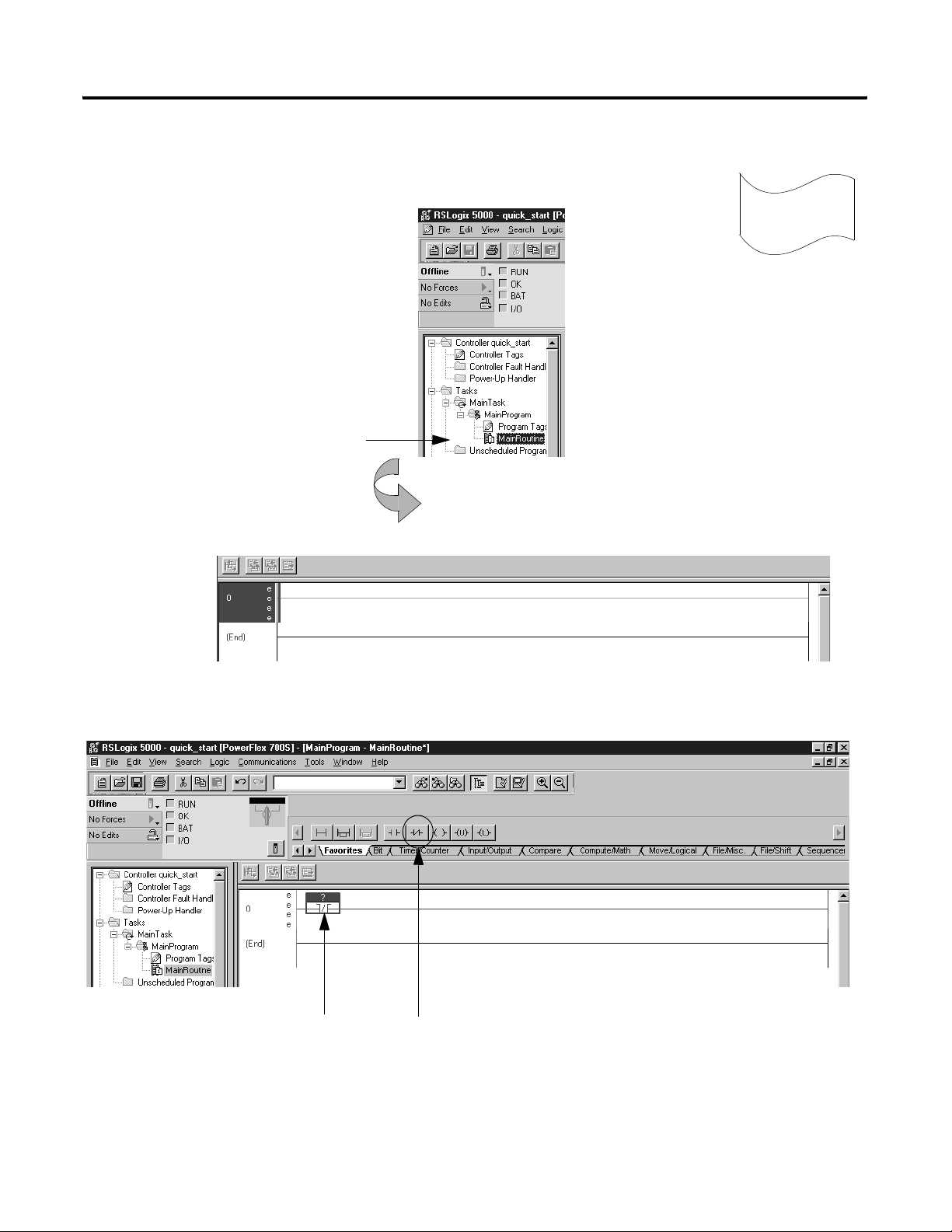
Entering logic
1. Use default task, program, and routine.
When you created the project, the software
automatically created a MainTask, MainProgram, and
MainRoutine. Use these defaults for this example.
Double-click MainRoutine.
5
Enter logic
The software displays an empty routine.
2. Enter an XIO instruction.
Drag and drop the XIO instruction on an empty rung.
Publication 20D-UM002C-EN-P - November 2003
Page 31

Entering logic (continued)
3. Assign a tag to the XIO instruction.
Double-click the tag area of the instruction.
Use the drop-down menu to select input_1.
Getting Started 1-19
Enter logic
5
The software displays an incomplete rung.
4. Enter this logic.
5. To save the project, from the File menu, select Save.
Publication 20D-UM002C-EN-P - November 2003
Page 32

1-20 Getting Started
Downloading a project
1. Make a serial connection from the workstation to the controller.
2. Configure an RSLinx communication driver:
6
Download
a project
A. In RSLinx software, select Communication → Configure Driver.
B. From the Available Driver Types list, select “RS-232 DF1 Devices”
and click Add New.
C. Select the “Logix5550/CompactLogix serial port” and specify the
COM port. Click Autoconfigure to have the software determine the
remaining serial settings.
3. Download the project from the Communications menu:
A. In RSLogix 5000 software, select Communication → “Who Active”.
B. Expand the DF1 network and select your controller.
C. Click Download. Confirm the download when prompted.
4. Place the controller in Remote Run mode.
Publication 20D-UM002C-EN-P - November 2003
Page 33

Viewing program scan time
1. View properties for the MainProgram.
A. Place the cursor over the MainProgram folder.
B. Click the right mouse button and select Properties.
Getting Started 1-21
7
View
status
2. Select the Configuration tab.
The Configuration tab displays the maximum
and last scan times for the program.
Publication 20D-UM002C-EN-P - November 2003
Page 34

1-22 Getting Started
Viewing controller memory usage
1. View properties for Controller quick_start.
A. Place the cursor over the Controller quick_start folder.
B. Click the right mouse button and select Properties.
2. Select the Advanced tab.
7
View
status
In addition to other information, the Advanced tab
Important: The amount of memory that the software displays includes
both the user available memory and the memory reserved for overhead.
See the specifications for your controller to determine how much memory
you have available for programming. This dialog box might display a higher
number, but the additional memory is required by system overhead and may
not be available for programming.
displays controller memory usage.
What To Do Next
Once your controller is installed and operating, you can use RSLogix™ 5000
programming software to develop and test your control application.
Use the remaining chapters in this manual as reference material for how the
DriveLogix controller operates in the Logix environment.
Publication 20D-UM002C-EN-P - November 2003
Page 35

What Is DriveLogix?
Chapter
2
Using This Chapter
The same RSLogix 5000
programming software supports
program development for all Logix
The DriveLogix controller is part of the Logix environment. The DriveLogix
controller provides a distributed control system built on these components:
• DriveLogix controller that supports the Logix instructions.
• RSLogix 5000 programming software that supports every
Logix controller.
• Direct connection to host PowerFlex 700S drive.
• FLEX™ I/O modules that provide a compact, DIN-rail mounted
I/O system.
• 1788 communication daughtercard that provides communication over a
standards-based ControlNet, EtherNet/IP or DeviceNet network.
1788 communication daughtercard installs
directly in the DriveLogix controller.
The DriveLogix controller
For information about: See page
developing programs 2-2
how the DriveLogix system uses connections 2-9
selecting a system overhead percentage 2-22
supports FLEX I/O modules.
1 Publication 20D-UM002C-EN-P - November 2003
Page 36

2-2 What Is DriveLogix?
Developing programs
control application
task 1
The controller operating system is a preemptive multitasking system that is
IEC 1131-3 compliant. This environment provides:
• tasks to configure controller execution
• programs to group data and logic
• routines to encapsulate executable code written in a single programming
language
controller fault handler
task 8
configuration
status
watchdog
program 1
main routine
program 32
program (local)
tags
fault routine
other routines
controller (global) tags I/O data system-shared data
Publication 20D-UM002C-EN-P - November 2003
Page 37

What Is DriveLogix? 2-3
Defining tasks
A task provides scheduling and priority information for a set of one or more
programs. You can configure tasks as either continuous or periodic. The
DriveLogix controller supports as many as 8 tasks, only one of which can
be continuous.
A task can have as many as 32 separate programs, each with its own executable
routines and program-scoped tags. Once a task is triggered (activated), all the
programs assigned to the task execute in the order in which they are grouped.
Programs can only appear once in the Controller Organizer and cannot be
shared by multiple tasks.
Specifying task priorities
Each task in the controller has a priority level. The operating system uses the
priority level to determine which task to execute when multiple tasks are
triggered. There are 15 configurable priority levels for periodic tasks that range
from 1-15, with 1 being the highest priority and 15 being the lowest priority. A
higher priority task will interrupt any lower priority task. The continuous task
has the lowest priority and is always interrupted by a periodic task.
The DriveLogix controller uses a dedicated periodic task at priority 7 to
process I/O data. This periodic task executes at the fastest RPI (Requested
Packet Interval) you have scheduled for the DriveLogix system. Its total
execution time is as long as it takes to scan the configured I/O modules.
How you configure your tasks affects how the controller receives I/O data.
Tasks at priorities 1-6 can starve the dedicated I/O task; tasks at priority 8-15
can be starved by the dedicated I/O task.
TIP
For typical applications, the periodic task priority should be
set at a priority level lower than 7. (Remember, priority
levels are ranked in ascending order–a priority lower than 7
means a priority level of 8-15.) The default priority of 10
should be sufficient for most applications.
If a periodic task must execute without interruption from
the I/O update task, set the priority level higher than 7 (i.e.
1-6).
Publication 20D-UM002C-EN-P - November 2003
Page 38

2-4 What Is DriveLogix?
5
The following example shows the task execution order for an application with
periodic tasks and a continuous task.
Tas k 1
Tas k 2
Tas k 3
Tas k 4
Task: Priority Level: Task Type: Actual
Execution Time:
1 5 20ms periodic task 2ms 2ms
2 7 dedicated I/O task
5ms fastest RPI
3 10 10ms periodic task 4ms 8ms
4 none (lowest) continuous task 25ms 60ms
1ms 3ms
Worst Case
Execution Time:
030252015105 454035 50 6
Notes:
A. The highest priority task interrupts all lower priority tasks.
B. The dedicated I/O task can be interrupted by tasks with priority levels
1-6. The dedicated I/O task interrupts tasks with priority levels 8-15.
This task runs at the fastest RPI rate scheduled for the DriveLogix
system (5ms in this example).
C. The continuous task runs at the lowest priority and is interrupted by all
other tasks.
D. A lower priority task can be interrupted multiple times by a higher
priority task.
E. When the continuous task completes a full scan it restarts immediately,
unless a higher priority task is running.
6055
Publication 20D-UM002C-EN-P - November 2003
Page 39

What Is DriveLogix? 2-5
Defining programs
Each program contains program tags, a main executable routine, other
routines, and an optional fault routine. Each task can schedule as many as 32
programs.
The scheduled programs within a task execute to completion from first to last.
Programs that aren’t attached to any task show up as unscheduled programs.
You must specify (schedule) a program within a task before the controller can
scan the program.
Defining routines
A routine is a set of logic instructions in a single programming language, such
as ladder logic. Routines provide the executable code for the project in a
controller. A routine is similar to a program file or subroutine in a PLC or
SLC processor.
Each program has a main routine. This is the first routine to execute when the
controller triggers the associated task and calls the associated program. Use
logic, such as the JSR instruction, to call other routines.
You can also specify an optional program fault routine. The controller
executes this routine if it encounters an instruction-execution fault within any
of the routines in the associated program.
Publication 20D-UM002C-EN-P - November 2003
Page 40

2-6 What Is DriveLogix?
Using the Event Task
The event task is available with DriveLogix controllers using firmware version
12.x or greater. Previously, the only tasks available were the continuous task
and periodic task. However, the event task offers DriveLogix controller users a
task that executes a section of logic immediately when an event occurs.
An event task performs a function only when a specific event (trigger) occurs.
Whenever the trigger for the event task occurs, the event task:
• interrupts any lower priority tasks
• executes one time
• returns control to where the previous task left off
For DriveLogix controller, the event task trigger can only be the EVENT
instruction.
Prioritizing Periodic and Event Tasks
Although a DriveLogix project can contain up to 8 tasks, the controller
executes only one task at a time. If a periodic or event task is triggered while
another task is currently executing, the priority of each task tells the controller
what to do.
The DriveLogix controller has 15 priority levels for its tasks. To assign a
priority to a task, use the guidelines described in Table 2.1.
Table 2.1
If you want: Then Notes:
this task to interrupt another
task
another task to interrupt this
task
this task to share controller
time with another task
Assign a priority number
that is less than (higher
priority) the priority number
of the other task.
Assign a priority number
that is greater than (lower
priority) the priority number
of the other task.
Assign the same priority
number to both tasks.
• A higher priority task
interrupts all lower
priority tasks.
• A higher priority task
can interrupt a lower
priority task multiple
times.
The controller switches back
and forth between each task
and executes each one for
1ms.
Publication 20D-UM002C-EN-P - November 2003
Page 41

Triggering the Event Task
To trigger an event task based on conditions in your logic, use the EVENT
Instruction trigger.
Let an event trigger this task.
Let an EVENT instruction trigger the task.
No tag is required.
The EVENT Instruction Only trigger requires that you use a Trigger Event Task
(EVENT) instruction to trigger the task. You can use an EVENT instruction
from multiple points in your project. Each time the instruction executes, it
triggers the specified event task.
What Is DriveLogix? 2-7
EVENT instruction in program A
EVENT instruction in program B
event task
1 2
Description:
Program A executes an EVENT instruction.
1
The event task that is specified by the EVENT instruction executes one time.
Program B executes an EVENT instruction.
2
The event task that is specified by the EVENT instruction executes one time.
Publication 20D-UM002C-EN-P - November 2003
Page 42

2-8 What Is DriveLogix?
Programmatically Determine if an EVENT Instruction Triggered
aTask
To determine if an EVENT instruction triggered an event task, use a
Get System Value (GSV) instruction to monitor the Status attribute of the
task.
Table 2.2 Status Attribute of the TASK Object
Attribute: Data Type: Instruction: Description:
Status DINT GSV
SSV
Provides status information about the task. Once the controller sets a bit, you
must manually clear the bit to determine if another fault of that type occurred.
To determine if: Examine this bit:
An EVENT instruction triggered the task (event task
only).
A timeout triggered the task (event task only). 1
An overlap occurred for this task. 2
0
The controller does not clear the bits of the Status attribute once they are set.
• To use a bit for new status information, you must manually clear the bit.
• Use a Set System Value (SSV) instruction to set the attribute to a
different value.
Checklist for an EVENT Instruction Task
For this: Make sure you:
❑ 1. EVENT instruction Use a Trigger Event Task (EVNT) instruction at each point in your logic that you
want to trigger the event task.
❑ 2. Task priority Configure the event task as the highest priority task.
If a periodic task has a higher priority, the event task may have to wait until the
periodic task is done.
❑ 3. Number of event tasks Limit the number of event tasks.
Each additional task reduces the processing time that is available for other tasks.
❑ 4. Automatic Output Processing For an event task, you can typically disable automatic output processing (default).
This could cause an overlap.
This reduces the elapsed time of the task.
Publication 20D-UM002C-EN-P - November 2003
For more information on using the event task, see Logix5000 Controllers
Common Procedures programming manual, publication 1756-PM001.
Page 43

What Is DriveLogix? 2-9
How the DriveLogix System Uses Connections
Method: Description:
scheduled connection
• most deterministic
• unique to ControlNet
The DriveLogix system uses a connection to establish a communication link
between two devices. The DriveLogix system has enough internal resources to
support a connection to every local I/O module and 32 connections through
the daughtercard (e.g. the 1788-ENBT card). However, the daughtercard’s
connection limit is the limiting factor when sizing a system.
Connections can be:
• controller to local I/O modules or local communication cards
• controller to remote I/O or remote communication modules
• controller to remote I/O (rack optimized) modules
• produced and consumed tags
• messages
You indirectly determine the number of connections the controller uses by
configuring the controller to communicate with other devices in the system.
Connections are allocations of resources that provide more reliable
communications between devices than unconnected messages. The
DriveLogix system supports both scheduled and unscheduled connections and
unconnected messages.
A scheduled connection is unique to ControlNet communications. A scheduled connection
lets you send and receive data repeatedly at a predetermined rate, which is the requested
packet interval (RPI). For example, a connection to an I/O module is a scheduled connection
because you repeatedly receive data from the module at a specified rate. Other scheduled
connections include connections to:
unscheduled connection
• deterministic
• used by both ControlNet and
EtherNet/IP
unconnected message
• least deterministic
• communication devices
• produced/consumed tags
On a ControlNet network, you must use RSNetWorx for ControlNet to enable all scheduled
connections and establish a network update time (NUT).
An unscheduled connection is a message transfer between controllers that is triggered by
the requested packet interval (RPI) or the program (such as a MSG instruction).
Unscheduled messaging lets you send and receive data when needed.
All EtherNet/IP connections are unscheduled.
An unconnected message is a message that does not require connection resources . An
unconnected message is sent as a single request/response.
Publication 20D-UM002C-EN-P - November 2003
Page 44

2-10 What Is DriveLogix?
The communication module you select determines the number of connections
you have available for I/O and messages:
This communication card: Supports this number of connections:
1788-CNx 32 connections–the maiximum number of scheduled
connections is dependent on the RPI:
RPI
(with 5 ms NUT)
5 ms 3
10 ms 6
20 ms 13
40 ms 20
The remaining connections (or all 32, if you have no
scheduled connections) can be used for unscheduled
connections
1788-ENBT 32 connections - can be used for explicit and implicit
connections
(all 32 connections are any combination of remote
I/O, produce/consume, and messaging connections)
How you configure connections determines how many remote devices a
communication card can support. If you have two communication cards, use
one for messaging (e.g. HMI) and the other for control of I/O. While one card
can support both functions, performance can improve by separating these
functions onto separate cards.
Max Scheduled
Connections
Determining Connections for Produced and Consumed Tags
This type of tag: Requires these connections:
produced By default, a produced tag allows two other controllers to consume the tag, which means
consumed Each consumed tag requires one connection for the controller that is consuming the tag.
Publication 20D-UM002C-EN-P - November 2003
The DriveLogix controller supports the ability to produce (broadcast) and
consume (receive) system-shared tags. Produced and consumed tags each
require connections. Over ControlNet, produced and consumed tags are
scheduled connections.
that as many as two controllers can simultaneously receive the tag data. The local
controller (producing) must have one connection for the produced tag and the first
consumer and one more connection for each additional consumer (heartbeat). The default
produced tag requires as many connections as there are consumers for the produced tag.
For example, if the 3 consumers will consume the produced tag, it requires 3 connections.
As you increase the number of controllers that can consume a produced tag, you also
reduce the number of connections the controller has available for other operations, like
communications and I/O.
Page 45

What Is DriveLogix? 2-11
DriveLogix controllers can produce and consume tags over:
• a ControlNet network
• an EtherNet/IP network.
Determining Connections for Messages
This type of message: And this communication method: Uses a connection:
CIP data table read or write X
PLC2, PLC3, PLC5, or SLC (all types) CIP
CIP generic CIP
IMPORTANT
The total number of tags that can be produced or consumed is limited by the
number of available connections and memory. If the controller uses all of its
connections for I/O and communication devices, no connections are left for
produced and consumed tags.
Messages transfer data to other devices, such as other controllers or operator
interfaces. Connected messages can leave the connection open (cache) or close
the connection when the message is done transmitting. The following table
shows which messages use a connection:
For two controllers to share produced or consumed
tags, both controllers must be attached to the same
control network (such as a ControlNet or Ethernet/IP
network). You cannot bridge produced and
consumed tags over two networks.
CIP with Source ID
DH+ X
Optional
(1)
block-transfer read or write X
(1)
You can connect CIP generic messages, but for most applications, we recommend you leave CIP generic messages unconnected.
Connected messages are unscheduled connections on both ControlNet and
EtherNet/IP networks.
If a MSG instruction uses a connection, you have the option to leave the
connection open (cache) or close the connection when the message is done
transmitting.
If you: Then:
Cache the connection The connection stays open after the MSG instruction is done.
This optimizes execution time. Opening a connection each time
the message executes increases execution time.
Do not cache the
connection
The connection closes after the MSG instruction is done. This
frees up that connection for other uses.
Publication 20D-UM002C-EN-P - November 2003
Page 46

2-12 What Is DriveLogix?
The controller has the following limits on the number of connections that you
can cache:
Determining Connections for I/O Modules
Connection: Description:
direct A direct connection is a real-time, data transfer link between the controller and an I/O
rack-optimized For digital I/O modules, you can select rack optimized communication. A rack optimized
If you have this software
and firmware revision:
11.x or earlier • block transfer messages for up to 16 connections
12.x or later up to 32 connections
The DriveLogix system uses connections to transmit I/O data. These
connections can either be direct connections or rack-optimized connection.
Over ControlNet, I/O connections are scheduled connections:
module. The controller maintains and monitors the connection between the controller and
the I/O module. Any break in the connection, such as a module fault or the removal of a
module while under power, causes the controller to set fault status bits in the data area
associated with the module.
connection consolidates connection usage between the controller and all the digital I/O
modules on a rack (or DIN rail). Rather than having individual, direct connections for each
I/O module, there is one connection for the entire rack (or DIN rail).
Then you can cache:
• other types of messages up to 16 connections
Connections for local I/O modules
The DriveLogix controller automatically assigns one rack-optimized
connection for the local DIN rail. You then configure each I/O module on the
DIN rail to either use that rack-optimized connection or to use a direct
connection. The rack-optimized connection for the DIN rail exists whether or
not you configure the I/O modules to use that rack-optimized connection.
The rack-optimized connection lets you organize all the digital I/O modules
on the DIN rail into one connection to the controller. Or you can choose to
configure each I/O module to have a direct connection to the controller.
Analog I/O modules must have a direct connection to the controller.
It is not as critical to manage the number of connections for local I/O
modules as it is for remote devices because the controller supports a direct
connection for each possible local I/O device.
Publication 20D-UM002C-EN-P - November 2003
Page 47

What Is DriveLogix? 2-13
Connections for remote devices
To optimize the number of available connections, place remote, digital I/O in
the same location and use a rack-optimized connection to the remote adapter
that connects the remote I/O to the DriveLogix system.
If you have remote analog I/O modules, or want a direct connection to
specific remote I/O modules, you do not have to create the rack-optimized
connection to the remote adapter. To use direct connections to remote I/O,
select “none” for the communication format of the remote communication
device.
!
EtherNet/IP
IMPORTANT
Direct connections for I/O modules
In this example, assume that each I/O module is configured for a direct
connection to the controller.
The following table calculates the connections in this example.
Connection: Amount:
DriveLogix controller to 3 local I/O modules
rack-optimized connection for the DIN rail
direct connection for each I/O module
DriveLogix controller to host PowerFlex 700S drive 1
It is vital that you manage your connections to remote
devices because, while the DriveLogix controller allows up
to 250 total connections, the communications cards that
connect to remote devices are limited to far fewer
connections (i.e. 32 connections for ControlNet or
EtherNet/IP).
1
3
total connections used: 4
Publication 20D-UM002C-EN-P - November 2003
Page 48

2-14 What Is DriveLogix?
Rack-optimized connections for I/O modules
EtherNet/IP
!
In this example, assume that each I/O module is configured for a
rack-optimized connection to the controller.
The following table calculates the connections in this example.
Connection: Amount:
DriveLogix controller to 3 local I/O modules
rack-optimized connection for the DIN rail 1
DriveLogix controller to host PowerFlex 700S drive 1
total connections used: 2
TIP
The rack-optimized connection conserves
connections and lowers controller overhead in the
I/O update task. However, the rack-optimized
connection also limits the status and diagnostic
information that is available from the I/O modules
and is limited to a single RPI.
!
EtherNet/IP
Combining direct and rack-optimized connections
A DIN rail can have both a rack-optimized connection and direct connections.
Assume that the I/O modules in slot 0 and slot 1 on the local rail are
configured for a rack-optimized connection and that the I/O module in slot 2
is configured for a direct connection.
The following table calculates the connections in this example.
Connection: Amount:
DriveLogix controller to 3 local I/O modules
rack-optimized connection for the DIN rail
direct connection for one I/O module (slot 2)11
DriveLogix controller to host PowerFlex 700S drive 1
total connections used: 3
Publication 20D-UM002C-EN-P - November 2003
Page 49

What Is DriveLogix? 2-15
Connections to remote ControlNet or EtherNet/IP devices
EtherNet/IP
!
A remote device over ControlNet and EtherNet/IP can be configured as
either a rack-optimized connection and direct connection. In this example, the
DriveLogix controller uses one rack-optimized connection to communicate
with the communication adapter to receive data from the digital I/O modules
(two in this example) and uses one direct connection to communicate with the
analog module.
The following table calculates the connections in this example.
Connection: Amount:
DriveLogix controller to 3 local I/O modules
rack-optimized connection for the DIN rail
direct connection for one I/O module (slot 2)11
DriveLogix controller to communication card
(1788-CNx or 1788-ENBT)
DriveLogix controller to communication adapter
(rack-optimized connection for digital I/O modules)
0
1
DriveLogix controller to remote analog I/O module 1
DriveLogix controller to host PowerFlex 700S drive 1
total connections used: 5
total connections through the
communications card:
2 – This number is within the
connection limits of either
the 1788-CNx card (maximum
connections = 9) or the
1788-ENBT card (maximum
connections = 32).
Publication 20D-UM002C-EN-P - November 2003
Page 50

2-16 What Is DriveLogix?
Connections to DeviceNet devices
In this example the controller uses two connections (one for status and one for
I/O) to communicate with the DeviceNet devices through the 1788-DNBO
module. The 1788-DNBO module uses a rack-optimized connection to the
DeviceNet devices.
DriveLogix controller
DeviceNet
network
PanelView 300
DeviceNet devices
The following table calculates the connections in this example.
Connection: Amount:
DriveLogix controller to 3 local I/O modules
rack-optimized connection for the DIN rail
direct connection for one I/O module (slot 2)
DriveLogix controller to the 1788-DNBO DeviceNet
communication card
DriveLogix controller to host PowerFlex 700S drive 1
(1)
DriveLogix controller connection to remote DeviceNet devices are accounted for in the 2 connections to the
1788-DNBO card.
(1)
total connections used: 5
1
1
2
Publication 20D-UM002C-EN-P - November 2003
The 1788-DNBO card does not establish connections to its devices; and
therefore, the controller does not establish connections with DeviceNet
devices. The 1788-DNBO module acts as a scanner that gathers all the data
from its devices and packs that data together into one image that is passed to
Page 51

What Is DriveLogix? 2-17
the controller. However, the controller can use a MSG instruction to get
information directly to or from a DeviceNet device.
Determining Total Connection Requirements
Connection Type: Device
connection to host PowerFlex 700S drive 1 1 1
rack-optimized connection for the local DIN rail 2 1 2
I/O module (rack-optimized connection) on local rail 0
I/O module (direct connection) on local rail 1
1788-CNx ControlNet communication card 0 0
1788-DNBO communication card (rack-optimized connection) 2
1788-ENBT Ethernet/IP communication card 0 0
To calculate the total connection requirements for a DriveLogix controller,
consider the connections to local I/O modules, the host PowerFlex 700S drive
and the connections to remote modules.
Use the following table to tally local connections:
Connections
Quantity:
Regardless of how you configure the I/O modules (rack-optimized or direct
connect) on the local rail, the controller establishes a rack-optimized
connection for the rail. The data for any I/O module configured for a
rack-optimized connection is stored in the rack-optimized connection for the
rail. You can have 8 I/O modules, for a maximum of 8 direct connections.
per Device:
Tota l
Connections:
total
Publication 20D-UM002C-EN-P - November 2003
Page 52

2-18 What Is DriveLogix?
Remote connections depend on the communication card. Use the following
table to tally remote connections:
Connection Type: Device
Quantity:
remote ControlNet communication device (such as a 1794-ACN15,
-ACNR15 or 1756-CNB, -CNBR module) configured as:
direct (none) connection or rack-optimized connection
listen-only rack-optimization (1756-CNB, -CNBR only)
remote I/O device over ControlNet (direct connection) 1
remote EtherNet/IP communication device (such as a 1794-AEN
adapter or 1756-ENBT module) configured as:
direct (none) connection or rack-optimized connection
listen-only rack-optimization (1756-ENBT only)
remote I/O device over EtherNet/IP (direct connection) 1
produced and consumed tag
produced tag and one consumer
each additional consumer
consumed tag 1
maximum active message 1
After calculating the number of remote connections, make sure they do not
exceed the limitations of the communication card:
• each ControlNet communication card supports 32 total connections, 9
of which can be scheduled (such as direct I/O connections and
produced and consumed tags)
Connections
per Device:
0 or 1
1
0 or 1
1
1
1
Tota l
Connections:
total
Publication 20D-UM002C-EN-P - November 2003
• the Ethernet/IP communication card supports 32 total connections of
any type
Even if the total number of connections is within the card limitations, the total
number of messages per second must also be within the card limitations. You
can estimate the number of messages per second for a connection as (2 * 1000
ms) / RPI.
The communication cards support:
• each ControlNet communication card supports 1490 messages/second
• the EtherNet/IP communication card supports 4000 messages/second
Page 53

This example system has these details:
What Is DriveLogix? 2-19
local rail
controller
• I/O modules on the local rail are digital, so configure each module for a
rack-optimized connection
• I/O modules on the extended-local rail are analog, so configure each
module for a direct connection
• I/O modules on the ControlNet network are 4 digital and 4 analog, so
configure each digital module for a rack-optimized connection and each
analog module for a direct connection
• there are no produced or consumed tags
• the controller sends 2 messages to other devices on the ControlNet
network
• the controller uses 2 connections to the 1788-DNBO module to collect
data from the DeviceNet devices
extended-local rail
ControlNet network
DeviceNet network
8 I/O modules
8 I/O modules
8 I/O modules
4 DeviceNet devices
Local connections
Connection Type: Device
Quantity:
rack-optimized connection to DIN rail 2 1 2
connection to host PowerFlex 700S drive 1 1 1
1788-DNBO communication card (rack-optimized connection) 1 2 2
Connections
per Device:
total
Remote connections
Connection Type: Device
remote ControlNet communication device
I/O module over ControlNet (direct connection) 4 1 4
cached message 2 1 2
configured as a rack-optimized connection
Quantity:
111
Connections
per Device:
total
Tota l
Connections:
5
Tota l
Connections:
7
Publication 20D-UM002C-EN-P - November 2003
Page 54

2-20 What Is DriveLogix?
Downloading Projects
1. Go online with the controller.
2. View properties for the controller and select the Nonvolatile Memory tab.
In general, you use the programming software to download a project from
your programming computer to the controller. The DriveLogix controller,
with expanded memory, supports nonvolatile memory for project storage.
IMPORTANT
To store a project in nonvolatile memory:
Nonvolatile memory stores the contents of user memory at
the time that you store the project.
• Changes that you make after you store the project are
not reflected in nonvolatile memory.
• If you want to store changes such as online edits, RPI
changes, tag values, or this particular DriveLogix
controller’s portion of the ControlNet network
schedule (i.e. the portion of the ControlNet schedule
that affects the ControlNet nodes this controller makes
connections to), store the project again after you make
changes.
Publication 20D-UM002C-EN-P - November 2003
Page 55

What Is DriveLogix? 2-21
3. Click the Load/Store button and specify when you want the controller to load the project from nonvolatile memory.
4. Click the Load button to load the project from nonvolatile memory into the controller.
You can select:
In this field: Select this option: If you want:
Load Image On Power Up to load memory when you turn on or cycle the chassis
power
On Corrupt Memory to load memory whenever there is no project in the
User Initiated only use RSLogix 5000 software to load a project
Load Mode Remote Program the controller to go to Remote Program mode after
Remote Run the controller to go to Remote Run mode after loading
After you load or store to or from nonvolatile memory, RSLogix 5000 software
goes offline from the controller.
For details on storing to nonvolatile memory or restoring from nonvolatile
memory, see the Logix5000 Controllers Common Procedures Programming Manual,
publication 1756-PM001.
controller and you turn on or cycle the chassis power
loading from nonvolatile memory
from nonvolatile memory
Publication 20D-UM002C-EN-P - November 2003
Page 56

2-22 What Is DriveLogix?
Selecting a System Overhead Percentage
1. View properties for the controller and select the Advanced tab.
The Controller Properties lets you specify a percentage for system overhead.
This percentage specifies the percentage of controller time (excluding the time
for periodic tasks) that is devoted to communication and background
functions
System overhead functions include
• communicating with programming and HMI devices (such as RSLogix
5000 software)
• responding to messages
• sending messages, including block-transfers
• re-establishing and monitoring I/O connections (such as RIUP
conditions); this does not include normal I/O communications that occur
during program execution
• bridging communications from the serial port of the controller to other
communication devices
The controller performs system overhead functions for up to 1 ms at a time. If
the controller completes the overhead functions in less than 1 ms, it resumes
the continuous task.
If communications are not completing fast enough, increase the system
overhead percentage. As you increase the system overhead percentage, the
overall program scan also increases.
Publication 20D-UM002C-EN-P - November 2003
Page 57

Legend:
What Is DriveLogix? 2-23
The following table shows the ratio between the continuous task and the
system overhead functions:
At this time slice: The continuous tasks runs for: And then overhead occurs for up
to:
10% 9 ms 1 ms
20% 4 ms 1 ms
33% 2 ms 1 ms
50% 1 ms 1 ms
At the default time slice of 10%, system overhead interrupts the continuous
task every 9ms (of continuous task time).
Task executes.
Task is interrupted (suspended).
system overhead
continuous task
periodic task
system overhead
continuous task
elapsed time (ms)
elapsed time (ms)
1 ms 1 ms
9 ms 9 ms
5 10152025
The interruption of a periodic task increases the elapsed time (clock time)
between the execution of system overhead.
1 ms 1 ms 1 ms 1 ms
1 ms 1 ms
9 ms of continuous task time 9 ms of continuous task time
5 10152025
Publication 20D-UM002C-EN-P - November 2003
Page 58

2-24 What Is DriveLogix?
system overhead
continuous task
system overhead
continuous task
If you increase the time slice to 20%, the system overhead interrupts the
continuous task every 4ms (of continuous task time).
1 ms 1 ms 1 ms 1 ms 1 ms
4 ms 4 ms 4 ms 4 ms 4 ms
5 10152025
elapsed time (ms)
If you increase the time slice to 50%, the system overhead interrupts the
continuous task every 1ms (of continuous task time).
1 ms
1 ms
5 10152025
elapsed time (ms)
periodic task
system overhead
elapsed time (ms)
If the controller only contains a periodic task (s), the system overhead timeslice
value has no effect. System overhead runs whenever a periodic task is not
running.
5 10152025
Publication 20D-UM002C-EN-P - November 2003
Page 59

Placing and Configuring the Drive
Chapter
3
Using This Chapter
Understanding the Interface to the Drive
For Information about: See page
Understanding the Interface to the Drive 3-1
Determining When the Controller Updates the Drive 3-3
Placing and Configuring the Drive 3-4
Inhibiting the Drive Connection 3-13
Using DriveExecutive Lite 3-15
Accessing Drive Data 3-23
Monitoring Drive Data 3-23
The DriveLogix controller supports a direct connection to the drive consisting
of 16 inputs and 16 outputs. The tag names and data types associated with the
inputs and outputs are determined by the communication format selection.
Currently, the following three communications formats are available:
• Velocity Control – for typical speed regulated applications
• Position Control – for typical positioning applications
• User-Defined Control – for general use as required.
• Motion Control - for use with Logix motion commands
• Custom User-Defined Control - for general use as required.
Each communication format contains a number of pre-defined tags and
user-defined tags.
The pre-defined tag names and data types correspond to the associated
parameters within the drive necessary to support the selected communications
format. Links must be established in the drive to support the pre-defined tags
and are configured using DriveExecutive software. Linking is a mechanism
within the drive that configures data flow within the drive. The links within the
drive to support the pre-defined tags are protected and must be present. If the
associated links are not present, or are deleted, the communication connection
between the controller and drive will be broken.
The user-defined tags are made up of a fixed number of REAL (floating point)
and DINT (double integer) data types. No links are required within the drive
to support these tags. Therefore, links may be created and deleted as required
with no affect on the communication connection between the controller and
the drive. The user-defined tags may be used to address application specific
data needs not covered by the pre-defined tags.
1 Publication 20D-UM002C-EN-P - November 2003
Page 60

3-2 Placing and Configuring the Drive
Mapping for Inputs and Outputs
For each of the 16 inputs or 16 outputs, there are two dedicated parameters
within the drive for a total of 64 parameters. One parameter is a DINT type
and the other is a REAL type. Selecting a communication format defines the
data types for each input and selects the correct parameter for each input and
output in the communication link. The remaining parameter is not utilized.
DriveLogix
Controller
Input Word 0
Input Word 1
Input Word 2
Input Word 3
Input Word 4
Input Word 5
Input Word 6
Input Word 7
Input Word 8
Input Word 9
Input Word 10
Input Word 11
Input Word 12
Input Word 13
Input Word 14
Input Word 15
PowerFlex 700S Drive Parameter
Number Name Data Type
632 Integer Out00 DINT
633 Real Out00 REAL
634 Integer Out01 DINT
635 Real Out01 REAL
636 Integer Out02 DINT
637 Real Out02 REAL
638 Integer Out03 DINT
639 Real Out03 REAL
640 Integer Out04 DINT
641 Real Out04 REAL
642 Integer Out05 DINT
643 Real Out05 REAL
644 Integer Out06 DINT
645 Real Out06 REAL
646 Integer Out07 DINT
647 Real Out07 REAL
648 Integer Out08 DINT
649 Real Out08 REAL
650 Integer Out09 DINT
651 Real Out09 REAL
652 Integer Out10 DINT
653 Real Out10 REAL
654 Integer Out11 DINT
655 Real Out11 REAL
656 Integer Out12 DINT
657 Real Out12 REAL
658 Integer Out13 DINT
659 Real Out13 REAL
660 Integer Out14 DINT
661 Real Out14 REAL
662 Integer Out15 DINT
663 Real Out15 REAL
Publication 20D-UM002C-EN-P - November 2003
Page 61

Placing and Configuring the Drive 3-3
DriveLogix
Controller
Output Word 0
Output Word 1
Output Word 2
Output Word 3
Output Word 4
Output Word 5
Output Word 6
Output Word 7
Output Word 8
Output Word 9
Output Word 10
Output Word 11
Output Word 12
Output Word 13
Output Word 14
Output Word 15
PowerFlex 700S Drive Parameter
Number Name Data Type
600 Integer In00 DINT
601 Real In00 REAL
602 Integer In01 DINT
603 Real In01 REAL
604 Integer In02 DINT
605 Real In02 REAL
606 Integer In03 DINT
607 Real In03 REAL
608 Integer In04 DINT
609 Real In04 REAL
610 Integer In05 DINT
611 Real In05 REAL
612 Integer In06 DINT
613 Real In06 REAL
614 Integer In07 DINT
615 Real In07 REAL
616 Integer In08 DINT
617 Real In08 REAL
618 Integer In09 DINT
619 Real In09 REAL
620 Integer In10 DINT
621 Real In10 REAL
622 Integer In11 DINT
623 Real In11 REAL
624 Integer In12 DINT
625 Real In12 REAL
626 Integer In13 DINT
627 Real In13 REAL
628 Integer In14 DINT
629 Real In14 REAL
630 Integer In15 DINT
631 Real In15 REAL
Determining When the Controller Updates the Drive
The DriveLogix controller follows a producer/consumer model for the drive
connection, similar to the interface to an I/O module. The drive acts as both
an input module, producing data for the controller; and an output module,
consuming data from the controller. Although the producer/consumer model
multi casts data, all data in the drive connection is exclusive to the DriveLogix
controller.
The controller updates the input and output data in the drive connection
asynchronously to the logic scan, consistent with the way it handles other I/O
data. All input data from the drive is read in a single block and all output data is
written to the drive in a single block.
Publication 20D-UM002C-EN-P - November 2003
Page 62

3-4 Placing and Configuring the Drive
1.I
I/O Confi
You must configure the Requested Packet Interval (RPI) rate for the drive.
This setting affects how fast the controller reads and writes the data in the
drive interface.
The Drive consumes data from the DriveLogix controller every 2 milliseconds,
and produces data to the controller every 2 milliseconds. The drive updates the
inputs and outputs to the controller asynchronous to both the program scan
and I/O scan of the controller.
Placing and Configuring the Drive
n the Controller Organizer, select the
folder and select New Module..
When you create a project for the DriveLogix controller in RSLogix 5000, the
Controller Organizer automatically displays the local DIN rail for Flex I/O.
You must add the PowerFlex 700S drive to the configuration, in a manner
similar to adding an I/O module. The Controller Organizer automatically
places the drive in slot two.
TIP
guration folder. Right-click the selected
If you want data to remain constant throughout one scan,
make a copy of the data at the beginning of the scan and
use the copy throughout the scan.
2. Select the drive (PowerFlex 700S-400V
in this example).
Publication 20D-UM002C-EN-P - November 2003
Page 63

Placing and Configuring the Drive 3-5
IMPORTANT
3. Configure the drive. Use the module properties wizard to specify characteristics for the module. Click Next
4. Click finish when you are done. The completed module appears in the Controller Organizer.
Electronic Keying
You must select the correct voltage rating for the drive,
when adding the drive. You can find this on the drive data
nameplate.
The selection you make for the Comm Format
determines the communication format for the
connection to the drive. This determines the tag names
and data types. See page 3-6. Once you complete
adding a module, you cannot change this selection.
Electronic keying has no effect on drive module. However, the default setting
(Compatible Module) is recommended.
Selecting “Compatible Module” allows you to enter the drive firmware minor
revision.
Revision
You must enter the correct drive VPL firmware revision, in order to launch
DriveExecutive Lite and create the appropriate links for the selected
communication format. Determine the firmware revision by viewing
parameter 314 [VPL Firmware Rev] in the drive.
Publication 20D-UM002C-EN-P - November 2003
Page 64

3-6 Placing and Configuring the Drive
Communication Formats
The communication format determines the data structure, tag names, and
required links for communication to the drive. Each communication format
has been structured to meet the requirements of a specific type of application
(Speed Control, Position Control, or general purpose), and supports a
different data structure. The links within the PowerFlex 700S required to
support the selected format are also different. Any of the available
communication formats create one direct connection to the drive.
You select the communication format when you configure the drive module.
The default communication format for the drive is Velocity Control. The tags
are created as controller-scoped tags. The following tag structure shows the
Velocity Control format. The tag structure for this example’s drive connection
has the tag name of “drive_module”.
Publication 20D-UM002C-EN-P - November 2003
Page 65

Placing and Configuring the Drive 3-7
The following tables show the tag names and their relation ship to parameters
in the drive. These examples use a module name of “drive_module”.
Table 3.1 Mapping for the Velocity Control Communication Format
DriveLogix Controller Outputs PowerFlex 700S Inputs
Data
Tag Nam e
drive_module:O.LogicCommand DINT 600 Integer In00 Logic Command 151
drive_module:O.SpeedRef1 REAL 603 Real In01 Speed Ref 1 10
drive_module:O.TorqueRef1 DINT 605 Real In02 Torque Ref 1 111
drive_module:O.SpdTorqModeSel DINT 606 Integer In03 Spd/Trq ModeSel 110
drive_module:O.TorqueStep REAL 609 Real In04 Torque Step 116
drive_module:O.SpdRegDroop REAL 611 Real In05 Spd Reg Droop 86
drive_module:O.UserDefinedRealData[0] REAL 613 Real In06
drive_module:O.UserDefinedRealData[1] REAL 615 Real In07
drive_module:O.UserDefinedRealData[2] REAL 617 Real In08
drive_module:O.UserDefinedRealData[3] REAL 619 Real In09
drive_module:O.UserDefinedRealData[4] REAL 621 Real In10
drive_module:O.UserDefinedRealData[5] REAL 623 Real In11
drive_module:O.UserDefinedRealData[6] REAL 625 Real In12
drive_module:O.UserDefinedIntegerData[0] DINT 626 Integer In13
drive_module:O.UserDefinedIntegerData[1] DINT 628 Integer In14
drive_module:O.UserDefinedIntegerData[2] DINT 630 Integer In15
Type
Parameter Linked Parameter
Number Name Name Number
DriveLogix Controller Inputs PowerFlex 700S Outputs
Tag Nam e
drive_module:I.LogicStatus DINT 632 Integer Out00 Logic Status 155
drive_module:I.FilteredSpdFdbk REAL 635 Real Out01 Filtered SpdFdbk 71
drive_module:I.MotorTorqueRef REAL 637 Real Out02 Motor Torque Ref 303
drive_module:I.OutputCurrent REAL 639 Real Out03 Output Current 308
drive_module:I.MCStatus DINT 640 Integer Out04 MC Status 555
drive_module:I.LocalIOStatus DINT 642 Integer Out05 Local I/O Status 824
drive_module:I.UserDefinedRealData[0] REAL 645 Real Out06
drive_module:I.UserDefinedRealData[1] REAL 647 Real Out07
drive_module:I.UserDefinedRealData[2] REAL 649 Real Out08
drive_module:I.UserDefinedRealData[3] REAL 651 Real Out09
drive_module:I.UserDefinedRealData[4] REAL 653 Real Out10
drive_module:I.UserDefinedRealData[5] REAL 655 Real Out11
drive_module:I.UserDefinedRealData[6] REAL 657 Real Out12
drive_module:I.UserDefinedIntegerData[0] DINT 658 Integer Out13
drive_module:I.UserDefinedIntegerData[1] DINT 660 Integer Out14
drive_module:I.UserDefinedIntegerData[2] DINT 662 Integer Out15
Data
Type
Parameter Linked Parameter
Number Name Name Number
Publication 20D-UM002C-EN-P - November 2003
Page 66

3-8 Placing and Configuring the Drive
Table 3.2 Mapping for the Position Control Communication Format
DriveLogix Controller Outputs PowerFlex 700S Inputs
Tag N ame
drive_module:O.LogicCommand DINT 600 Integer In00 Logic Command 151
drive_module:O.SpeedRef1 REAL 603 Real In01 Speed Ref 1 10
drive_module:O.TorqueRef1 REAL 605 Real In02 Torque Ref 1 111
drive_module:O.SpdTorqModeSel DINT 606 Integer In03 Spd/Trq ModeSel 110
drive_module:O.TorqueStep REAL 609 Real In04 Torque Step 116
drive_module:O.SpdRegDroop REAL 611 Real In05 Spd Reg Droop 86
drive_module:O.PositionControl DINT 612 Integer In06 Position Control 740
drive_module:O.CoarsePositTrgt DINT 614 Integer In07 CoarsePosit Trgt 748
drive_module:O.PtPtPositRef DINT 616 Integer In08 Pt-Pt Posit Ref 758
drive_module:O.PositRefSel DINT 618 Integer In09 Posit Ref Sel 742
drive_module:O.PositOffset1 DINT 620 Integer In10 Posit Offset 1 753
drive_module:O.UserDefinedRealData[0] REAL 623 Real In11
drive_module:O.UserDefinedRealData[1] REAL 625 Real In12
drive_module:O.UserDefinedRealData[2] REAL 627 Real In13
drive_module:O.UserDefinedIntegerData[0] DINT 628 Integer In14
drive_module:O.UserDefinedIntegerData[1] DINT 630 Integer In15
Data
Type
Parameter Li nked Parameter
Number Name Name Number
DriveLogix Controller Inputs PowerFlex 700S Outputs
Data
Tag N ame
drive_module:I.LogicStatus DINT 632 Integer Out00 Logic Status 155
drive_module:I.FilteredSpdFdbk REAL 635 Real Out01 Filtered SpdFdbk 71
drive_module:I.MotorTorqueRef REAL 637 Real Out02 Motor Torque Ref 303
drive_module:I.OutputCurrent REAL 639 Real Out03 Output Current 308
drive_module:I.MCStatus DINT 640 Integer Out04 MC Status 555
drive_module:I.LocalIOStatus DINT 642 Integer Out05 Local I/O Status 824
drive_module:I.MtrPositFdbk DINT 644 Integer Out06 Mtr Posit Fdbk 762
drive_module:I.ActMotorPosit DINT 646 Integer Out07 Act Motor Posit 763
drive_module:I.PositionStatus DINT 648 Integer Out08 Position Status 741
drive_module:I.PositionError DINT 650 Integer Out09 Position Error 769
drive_module:I.UserDefinedRealData[0] REAL 653 Real Out10
drive_module:I.UserDefinedRealData[1] REAL 655 Real Out11
drive_module:I.UserDefinedRealData[2] REAL 657 Real Out12
drive_module:I.UserDefinedRealData[3] REAL 659 Real Out13
drive_module:I.UserDefinedIntegerData[0] DINT 660 Integer Out14
drive_module:I.UserDefinedIntegerData[1] DINT 662 Integer Out15
Type
Parameter Li nked Parameter
Number Name Name Number
Publication 20D-UM002C-EN-P - November 2003
Page 67

Placing and Configuring the Drive 3-9
Table 3.3 Mapping for the User-Defined Control Communication Format
DriveLogix Controller Outputs PowerFlex 700S Inputs
Tag Nam e
drive_module:O.LogicCommand DINT 600 Integer In00 Logic Command 151
drive_module:O.UserDefinedRealData[0] REAL 603 Real In01
drive_module:O.UserDefinedRealData[1] REAL 605 Real In02
drive_module:O.UserDefinedRealData[2] REAL 607 Real In03
drive_module:O.UserDefinedRealData[3] REAL 609 Real In04
drive_module:O.UserDefinedRealData[4] REAL 611 Real In05
drive_module:O.UserDefinedRealData[5] REAL 613 Real In06
drive_module:O.UserDefinedRealData[6] REAL 615 Real In07
drive_module:O.UserDefinedRealData[7] REAL 617 Real In08
drive_module:O.UserDefinedRealData[8] REAL 619 Real In09
drive_module:O.UserDefinedRealData[9] REAL 621 Real In10
drive_module:O.UserDefinedRealData[10] REAL 623 Real In11
drive_module:O.UserDefinedRealData[11] REAL 625 Real In12
drive_module:O.UserDefinedIntegerData[0] DINT 626 Integer In13
drive_module:O.UserDefinedIntegerData[1] DINT 628 Integer In14
drive_module:O.UserDefinedIntegerData[2] DINT 630 Integer In15
Data
Type
Parameter Linked Parameter
Number Name Name Number
DriveLogix Controller Inputs PowerFlex 700S Outputs
Data
Tag Nam e
drive_module:I.LogicStatus DINT 632 Integer Out00 Logic Status 155
drive_module:I.UserDefinedRealData[0] REAL 635 Real Out01
drive_module:I.UserDefinedRealData[1] REAL 637 Real Out02
drive_module:I.UserDefinedRealData[2] REAL 639 Real Out03
drive_module:I.UserDefinedRealData[3] REAL 641 Real Out04
drive_module:I.UserDefinedRealData[4] REAL 643 Real Out05
drive_module:I.UserDefinedRealData[5] REAL 645 Real Out06
drive_module:I.UserDefinedRealData[6] REAL 647 Real Out07
drive_module:I.UserDefinedRealData[7] REAL 649 Real Out08
drive_module:I.UserDefinedRealData[8] REAL 651 Real Out09
drive_module:I.UserDefinedRealData[9] REAL 653 Real Out10
drive_module:I.UserDefinedRealData[10] REAL 655 Real Out11
drive_module:I.UserDefinedRealData[11] REAL 657 Real Out12
drive_module:I.UserDefinedIntegerData[0] DINT 658 Integer Out13
drive_module:I.UserDefinedIntegerData[1] DINT 660 Integer Out14
drive_module:I.UserDefinedIntegerData[2] DINT 662 Integer Out15
Type
Parameter Linked Parameter
Number Name Name Number
Publication 20D-UM002C-EN-P - November 2003
Page 68

3-10 Placing and Configuring the Drive
Table 3.4 Mapping for the Motion Control Communication Format
DriveLogix Controller Outputs PowerFlex 700S Inputs
Tag N ame
drive_module:O.UserDefinedRealData[0] REAL 601 Real In00
drive_module:O.UserDefinedRealData[1] REAL 603 Real In01
drive_module:O.UserDefinedRealData[2] REAL 605 Real In02
drive_module:O.UserDefinedRealData[3] REAL 606 Real In03
drive_module:O.UserDefinedRealData[4] REAL 609 Real In04
drive_module:O.UserDefinedRealData[5] REAL 611 Real In05
drive_module:O.UserDefinedRealData[6] REAL 613 Real In06
drive_module:O.UserDefinedRealData[7] REAL 615 Real In07
drive_module:O.UserDefinedRealData[8] REAL 617 Real In08
drive_module:O.UserDefinedRealData[9] REAL 619 Real In09
drive_module:O.UserDefinedRealData[10] REAL 621 Real In10
drive_module:O.UserDefinedRealData[11] REAL 623 Real In11
drive_module:O.UserDefinedIntegerData[0] DINT 624 Integer In12
drive_module:O.UserDefinedIntegerData[1] DINT 626 Integer In13
drive_module:O.UserDefinedIntegerData[2] DINT 628 Integer In14
drive_module:O.UserDefinedIntegerData[2] DINT 630 Integer In15
Data
Type
Parameter Li nked Parameter
Number Name Name Number
DriveLogix Controller Inputs PowerFlex 700S Outputs
Data
Tag N ame
drive_module:I.LogicStatus DINT 632 Integer Out00 Logic Status 155
drive_module:I.UserDefinedRealData[0] REAL 635 Real Out01
drive_module:I.UserDefinedRealData[1] REAL 637 Real Out02
drive_module:I.UserDefinedRealData[2] REAL 639 Real Out03
drive_module:I.UserDefinedRealData[3] REAL 641 Real Out04
drive_module:I.UserDefinedRealData[4] REAL 643 Real Out05
drive_module:I.UserDefinedRealData[5] REAL 645 Real Out06
drive_module:I.UserDefinedRealData[6] REAL 647 Real Out07
drive_module:I.UserDefinedRealData[7] REAL 649 Real Out08
drive_module:I.UserDefinedRealData[8] REAL 651 Real Out09
drive_module:I.UserDefinedRealData[9] REAL 653 Real Out10
drive_module:I.UserDefinedRealData[10] REAL 655 Real Out11
drive_module:I.UserDefinedRealData[11] REAL 657 Real Out12
drive_module:I.UserDefinedIntegerData[0] DINT 658 Integer Out13
drive_module:I.UserDefinedIntegerData[1] DINT 660 Integer Out14
drive_module:I.UserDefinedIntegerData[2] DINT 662 Integer Out15
Type
Parameter Li nked Parameter
Number Name Name Number
Publication 20D-UM002C-EN-P - November 2003
Page 69

Placing and Configuring the Drive 3-11
Table 3.5 Mapping for the Custom User-Defined Control Communication Format
DriveLogix Controller Outputs PowerFlex 700S Inputs
Tag Nam e
drive_module:O.LogicCommand DINT 600 Integer In00 Logic Command 151
drive_module:O.UserDefinedRealData[0] REAL 603 Real In01
drive_module:O.UserDefinedRealData[1] REAL 605 Real In02
drive_module:O.UserDefinedRealData[2] REAL 607 Real In03
drive_module:O.UserDefinedRealData[3] REAL 609 Real In04
drive_module:O.UserDefinedRealData[4] REAL 611 Real In05
drive_module:O.UserDefinedRealData[5] REAL 613 Real In06
drive_module:O.UserDefinedRealData[6] REAL 615 Real In07
drive_module:O.UserDefinedRealData[7] REAL 617 Real In08
drive_module:O.UserDefinedIntegerData[0] DINT 618 Integer In09
drive_module:O.UserDefinedIntegerData[1] DINT 620 Integer In10
drive_module:O.UserDefinedIntegerData[2] DINT 622 Integer In11
drive_module:O.UserDefinedIntegerData[3] DINT 624 Integer In12
drive_module:O.UserDefinedIntegerData[4] DINT 626 Integer In13
drive_module:O.UserDefinedIntegerData[5] DINT 628 Integer In14
drive_module:O.UserDefinedIntegerData[6] DINT 630 Integer In15
Data
Type
Parameter Linked Parameter
Number Name Name Number
DriveLogix Controller Inputs PowerFlex 700S Outputs
Data
Tag Nam e
drive_module:I.LogicStatus DINT 632 Integer Out00 Logic Status 155
drive_module:I.UserDefinedRealData[0] REAL 635 Real Out01
drive_module:I.UserDefinedRealData[1] REAL 637 Real Out02
drive_module:I.UserDefinedRealData[2] REAL 639 Real Out03
drive_module:I.UserDefinedRealData[3] REAL 641 Real Out04
drive_module:I.UserDefinedRealData[4] REAL 643 Real Out05
drive_module:I.UserDefinedRealData[5] REAL 645 Real Out06
drive_module:I.UserDefinedRealData[6] REAL 647 Real Out07
drive_module:I.UserDefinedRealData[7] REAL 649 Real Out08
drive_module:I.UserDefinedIntegerData[0] DINT 650 Integer Out09
drive_module:I.UserDefinedIntegerData[1] DINT 652 Integer Out10
drive_module:I.UserDefinedIntegerData[2] DINT 654 Integer Out11
drive_module:I.UserDefinedIntegerData[3] DINT 656 Integer Out12
drive_module:I.UserDefinedIntegerData[4] DINT 658 Integer Out13
drive_module:I.UserDefinedIntegerData[5] DINT 660 Integer Out14
drive_module:I.UserDefinedIntegerData[6] DINT 662 Integer Out15
Type
Parameter Linked Parameter
Number Name Name Number
For each of the communication formats, drive_module:O.LogicCommand and
drive_module:I.LogicStatus are provided as DINT data types. In addition to
these tags, the control bits for each are also available as Boolean values with tag
names that correspond to the control bits in the drive. This gives you the
option of programming the Logic Command and Status words at the Boolean
level or as an integer value.
Publication 20D-UM002C-EN-P - November 2003
Page 70

3-12 Placing and Configuring the Drive
Not all 32-bits within parameter 151 [Logic Command], are directly visible in
the PowerFlex 700S. To view all 32-bits, refer to parameter 152 [Applied
LogicCmd].
DriveLogix Controller Outputs PowerFlex 700S Inputs
Data
Tag N ame
drive_module:O.LogicCommand DINT 600 Integer In00 Applied LogicCmd 152
drive_module:O.SpdRampDsbl BOOL bit 0 Integer In00 SpdRamp Dsbl bit 0
drive_module:O.SpdSCrvEn BOOL bit 1 Integer In00 Spd S Crv En bit 1
drive_module:O.TachLossRst BOOL bit 2 Integer In00 TachLoss Rst bit 2
drive_module:O.TimeAxisEn BOOL bit 3 Integer In00 Time Axis En bit 3
drive_module:O.MCAtuneEn BOOL bit 4 Integer In00 MC Atune En bit 4
drive_module:O.DirCtrlEn BOOL bit 6 Integer In00 Dir Sel En bit 6
drive_module:O.PMOffsetEn BOOL bit 7 Integer In00 PM Offset En bit 7
drive_module:O.MtrInertEn BOOL bit 8 Integer In00 Mtr Inert En bit 8
drive_module:O.SysInertEn BOOL bit 9 Integer In00 Sys Inert En bit 9
drive_module:O.InertiaComp BOOL bit 10 Integer In00 Inertia Comp bit 10
drive_module:O.FrictComp BOOL bit 11 Integer In00 Frict Comp bit 11
drive_module:O.ProcsTrimEn BOOL bit 12 Integer In00 ProcsTrim En bit 12
drive_module:O.PositionEnbl BOOL bit 13 Integer In00 PositionEnbl bit 13
drive_module:O.NormalStop BOOL bit 16 Integer In00 Normal Stop bit 16
drive_module:O.Start BOOL bit 17 Integer In00 Start bit 17
drive_module:O.Jog1 BOOL bit 18 Integer In00 Jog 1 bit 18
drive_module:O.ClearFault BOOL bit 19 Integer In00 Clear Fault bit 19
drive_module:O.UnipolFwd BOOL bit 20 Integer In00 Unipol Fwd bit 20
drive_module:O.UnipolRev BOOL bit 21 Integer In00 Unipol Rev bit 21
drive_module:O.Jog2 BOOL bit 23 Integer In00 Jog 2 bit 23
drive_module:O.CurrLimStop BOOL bit 24 Integer In00 CurrLim Stop bit 24
drive_module:O.CoastStop BOOL bit 25 Integer In00 Coast Stop bit 25
Type
Parameter Linked Parameter
Number Name Name Number
DriveLogix Controller Outputs
Data
Tag N ame
drive_module:I.LogicStatus DINT 600 Integer In00 Logic Status 155
drive_module:I.Enabled BOOL bit 0 Integer In00 Enabled bit 0
drive_module:I.Running BOOL bit 1 Integer In00 Running bit 1
drive_module:I.CommandDir BOOL bit 2 Integer In00 Command Dir bit 2
drive_module:I.ActualDir BOOL bit 3 Integer In00 Actual Dir bit 3
drive_module:I.Accelerating BOOL bit 4 Integer In00 Accelerating bit 4
drive_module:I.Decelerating BOOL bit 5 Integer In00 Decelerating bit 5
drive_module:I.Jogging BOOL bit 6 Integer In00 Jogging bit 6
drive_module:I.Faulted BOOL bit 7 Integer In00 Faulted bit 7
drive_module:I.Alarm BOOL bit 8 Integer In00 Alarm bit 8
drive_module:I.FlashMode BOOL bit 9 Integer In00 Flash Mode bit 9
drive_module:I.RunReady BOOL bit 10 Integer In00 Run Ready bit 10
drive_module:I.AtLimit BOOL bit 11 Integer In00 At Limit bit 11
drive_module:I.TachLossSw BOOL bit 12 Integer In00 Tach Loss Sw bit 12
drive_module:I.AtZeroSpd BOOL bit 13 Integer In00 At Zero Spd bit 13
drive_module:I.AtSetptSpd BOOL bit 14 Integer In00 At Setpt Spd bit 14
drive_module:I.AtSetpt1 BOOL bit 16 Integer In00 At Setpt 1 bit 16
drive_module:I.AboveSetpt2 BOOL bit 17 Integer In00 Above Setpt2 bit 17
drive_module:I.MCEnAck BOOL bit 28 Integer In00 MC En Ack bit 28
drive_module:I.MCCommis BOOL bit 19 Integer In00 MC Commis bit 19
drive_module:I.SpdCommis BOOL bit 20 Integer In00 Spd Commis bit 20
drive_module:I.TorqueMode BOOL bit 22 Integer In00 Torque Mode bit 22
drive_module:I.SpeedMode BOOL bit 23 Integer In00 Speed Mode bit 23
drive_module:I.PositionMode BOOL bit 24 Integer In00 PositionMode bit 24
drive_module:I.StartActive BOOL bit 25 Integer In00 Start Active bit 25
drive_module:I.CommandRun BOOL bit 26 Integer In00 Command Run bit 26
Type
PowerFlex 700S Inputs
Parameter Linked Parameter
Number Name Name Number
Publication 20D-UM002C-EN-P - November 2003
Page 71

Placing and Configuring the Drive 3-13
Inhibiting the Drive Connection
On the Connection tab during creation or in the Properties window
Check the inhibit box to
inhibit the connection to
the drive
RSLogix 5000 programming software allows you to inhibit the controller’s
connection to the drive, in the same way you inhibit its connection to an I/O
module. Inhibiting the drive module shuts down the connection from the
controller to the drive. When you create the module you can choose to inhibit
it. After you have created the module you can inhibit or un-inhibit it by
manipulating its properties window.
ATTENTION
!
Inhibiting a drive module breaks the controller’s
connection to the drive. In this situation, the controller can
neither, start/stop the drive nor read the status of the drive.
The drive can continue to operate based on its parameter
settings and inputs. To avoid potential personal injury and
damage to machinery, make sure this does not create unsafe
operation.
When you inhibit the drive module, the Controller Organizer displays
a yellow attention symbol
If you are: Inhibit the drive module to:
offline put a place holder for the drive module to indicate that configuration is not yet complete.
The inhibit status is stored in the project. When you download the project, the module is still inhibited.
online stop communication to the drive.
If you inhibit the drive while you are connected to the module, the connection to the module is closed. By default, the
PowerFlex 700S drive will fault. The data inputs to the drive will either hold last state, or reset to zero data based on the
setting of parameter 385 [Lgx Comm Loss Data].
If you inhibit the drive but a connection to the module was not established (perhaps due to an error condition or fault), the
module is inhibited. The module status information changes to indicate that the module is inhibited and not faulted.
If you uninhibit the drive (clear the check box), and no fault condition occurs, a connection is made to the drive.
over the module.
!
Publication 20D-UM002C-EN-P - November 2003
Page 72

3-14 Placing and Configuring the Drive
To inhibit a module from logic, you must first read the Mode attribute for the
module using a GSV instruction. Set bit 2 to the inhibit status (1 to inhibit or 0
to uninhibit). Use a SSV instruction to write the Mode attribute back to the
module. For example:
Publication 20D-UM002C-EN-P - November 2003
Page 73

Placing and Configuring the Drive 3-15
Using DriveExecutive Lite
1. If not already done, enter the drive firmware revision. Click the Finish button to apply the
revision data
In order to launch DriveExecutive Lite from within RSLogix 5000, the drives
power rating must be selected. The drive firmware revision must be applied
prior to selecting the power rating.
2. In the Controller Organizer, select the PowerFlex 700S drive. Right-click the drive module and select Properties
3. Select the Power tab.
4. Select the correct Drive Rating. This data can be found on the PowerFlex 700S data nameplate.
Publication 20D-UM002C-EN-P - November 2003
Page 74

3-16 Placing and Configuring the Drive
TIP
5. Once the power rating is selected, apply your changes by selecting the Apply button.
If your drive’s power rating does not appear as a selection,
you do not have the DriveExecutive Lite database file for
your drive. To create a database file, connect to the drive
with DriveExecutive Lite. This will automatically create the
database. You can also download the database file from
http://www.ab.com/drives/data.html
6. Select the Setup tab.
7. Enter the file name for your DriveExecutive Lite parameter file, then click the Apply button.
Publication 20D-UM002C-EN-P - November 2003
Page 75

8. Click the DriveExecutive button to launch DriveExecutive Lite.
9. When asked to create a new DriveExecutive Lite file, select yes.
Placing and Configuring the Drive 3-17
DriveExecutive will then launch and
open the newly created file
Publication 20D-UM002C-EN-P - November 2003
Page 76

3-18 Placing and Configuring the Drive
1. To view the setup screen select Peer Communication from the Drive drop-down menu. Then select the From Controller
Viewing the Communication Interface to the Controller
DriveExecutive Lite has a setup screen that details the communication
interface between the controller and drive. From this screen, the relationship
between drive parameters and controller tags is presented for the selected
communication format. You can create additional links within the drive for use
with the user-defined tags in the controller.
Important: In some revisions of DriveExecutive programming software, the
“From Controller” and “To Controller” tabs may be labled “From
DriveLogix” and “To DriveLogix”.
Publication 20D-UM002C-EN-P - November 2003
Page 77

Placing and Configuring the Drive 3-19
2. To send additional data from the drive to the controller go to the To Controller tab. Click the To Controller tab.Select the
desired source for the user-defined tag (Output Voltage in this example).
TIP
Configuring the Drive’s Response to a Connection Failure or
Controller Mode Change
The drive contains several parameters that allow you to configure the drive’s
response to communication loss to the controller. From the drive’s
perspective, a communication loss can come in the following two forms.
• The controller closes the connection (for example, the connection is
inhibited).
• A general failure occurs causing the connection to time out.
Parameter 386 [Lgx OutofRunCnfg] configures the drive’s response to the
controller is removed from the Run Mode. Parameter 387 [Lgx Timeout Cnfg]
configures the drive’s response to a general connection failure as detected by
the drive. Parameter 388 [Lgx Closed Cnfg] configures the drive’s response to
the controller closing the connection. All of these parameters configure the
drive’s response to these exception events in the following ways: ignore, alarm,
fault and coast to stop, fault and ramp to stop, fault and stop in current limit.
Use a UserDefinedRealData tag for parameters that
contain floating point data, and use a
UserDefinedIntegerData tag for parameters that contain
integer data.
Publication 20D-UM002C-EN-P - November 2003
Page 78

3-20 Placing and Configuring the Drive
Parameter 385 [Lgx CommLossData] determines what the drive does with
data from the controller when communication is lost. It determines if the drive
resets the data to zero or holds the data in its last state.
Configure these parameters, using DriveExecutive Lite. Locate them in the
Fault/Alm Config group of the Utility file.
Publication 20D-UM002C-EN-P - November 2003
Page 79

1. Select Properties from the Drive menu.
Placing and Configuring the Drive 3-21
Using Existing DriveExecutive Lite Files
Before using an existing DriveExecutive Lite file, verify the firmware revision,
communication format, and power rating in the drive file match the data
entered in drive module properties in your DriveLogix application.
2. View revision and ratings on the General tab of the Properties window.
3. Refer to Viewing the Communication Interface to the Controller on page 3-18, to view the communication format.
Publication 20D-UM002C-EN-P - November 2003
Page 80

3-22 Placing and Configuring the Drive
4. TIn RSLogix 5000, go to the Setup tab of the Properties window. Click the Browse button. Select the existing DriveExecutive file
(Existing Drive.dno in this example). Click the Open button.
5. Click the Apply button and launch DriveExecutive Lite.
Publication 20D-UM002C-EN-P - November 2003
Page 81

Placing and Configuring the Drive 3-23
Accessing Drive Data
Drive data is displayed as structures of multiple tags. The names and data
structures are based on the selected communication format. The programming
software automatically creates the necessary structures and tags when you
configure the drive module. Each tag name follows this format:
ModuleName:Type.MemberName.SubMemberName.Bit
where:
This address
variable:
ModuleName Identifies the module name entered during the drive module
Type Type of data
MemberName Specific data from the drive; depends on the selected
Is:
configuration
I = input
O = output
communication format.
Monitoring Drive Data
For tags associated with pre-defined data links, this name will
be the same as the corresponding parameter name in the drive.
SubMemberName Specific data related to a MemberName
Bit (optional) Specific bit of a DINT data value
Refer to Communication Formats on page 3-6 for sample tag names.
The DriveLogix controller offers different levels at which you can monitor the
drive module. You can:
• configure the drive module so that the controller faults if the drive loses
its connection to the controller.
• use the programming software to display fault data
• program logic to monitor fault data so you can take appropriate action
Publication 20D-UM002C-EN-P - November 2003
Page 82

3-24 Placing and Configuring the Drive
Check this box to configure the drive
module to generate a major fault if it
loses its connection to the controller
Configuring the Controller’s Response to a Connection Failure
You can configure the drive module to generate a major fault in the controller
if the drive loses its connection to the controller.
If you do not configure the major fault to occur, you should monitor the drive
module status. If the drive loses its connection to the controller:
• Outputs remain in their last
• Inputs remain in their last state
• By default the drive will fault
ATTENTION
!
Configure the drive to generate a controller major fault when the drive loses its
connection to the controller. Or, monitor the status of the drive module.
If a drive loses its connection to the controller, the
controller and other I/O modules continue to operate
based on old data from the drive, and the drive can
continue to operate based on old data from the controller.
To avoid potential personal injury and damage to
machinery, make sure this does not create unsafe operation.
Publication 20D-UM002C-EN-P - November 2003
Page 83

Monitoring the drive module
Each communication format provides a drive status word that will indicate
when a drive fault or alarm occurs. To view this data through the programming
software:
1. In the Controller Organizer, select Controller Tags. Right-click the selected icon and select Monitor Tags.
2. Expand the data as necessary.
Placing and Configuring the Drive 3-25
You can write logic to monitor these bits and take appropriate action if a fault
or alarm occurs. For example, you may want a drive alarm to turn on a warning
lamp and a drive fault to sound an alarm and set the motor brake.
EXAMPLE
Given this configuration, the following logic checks the
fault and alarm drive status bits.
Publication 20D-UM002C-EN-P - November 2003
Page 84

3-26 Placing and Configuring the Drive
Notes:
Publication 20D-UM002C-EN-P - November 2003
Page 85

Using This Chapter
Chapter
Placing and Configuring Local I/O
For information about: See page
Placing local I/O modules 4-2
Determining when the controller updates local I/O 4-3
Configuring a DIN rail 4-5
Configuring local I/O modules 4-6
Inhibiting I/O module operation 4-10
Accessing I/O data 4-13
Monitoring I/O modules 4-16
4
The DriveLogix controller supports a local DIN rail of as many as 8 I/O
modules.
1 Publication 20D-UM002C-EN-P - November 2003
Page 86

4-2 Placing and Configuring Local I/O
Placing Local I/O Modules
When you create a project for a DriveLogix controller, the Controller
Organizer for that project automatically displays the local DIN rail.
You must configure an RPI rate for the DIN rail. This rate applies to all the
I/O modules you install on the DIN rail.
.
If you have: The fastest possible RPI is:
one rail of digital I/O modules 30 ms
one rail of analog I/O modules 30 ms
one rail of digital and analog I/O modules mixed 30 ms
The DriveLogix controller uses to two services to scan I/O: the FlexBus and
the controller itself.
IMPORTANT
Slot 0Slot 1Slot 2Slot 3Slot 4Slot 5Slot 6Slot 7
Controller scan
FlexBus scan
When installing local I/O with a DriveLogix controller in a
high power drive, the length of the FLEXBUS cable must
not exceed 3 ft.
Publication 20D-UM002C-EN-P - November 2003
Page 87

Placing and Configuring Local I/O 4-3
The FlexBus continually scans all the slots (0-7) on the DIN rail. The FlexBus
scans the DIN rail, starting with slot 0, then scanning slot 1, and continuing
with all the slots, and then repeating the cycle. Even if a module is inhibited or
a slot is empty, the FlexBus scans that slot. The FlexBus scan identifies where
modules reside and collects module data for the controller scan.
The controller scans only those modules that are configured in the Control
Organizer. This scan updates the module tags with current data. The RPI for
the DIN rail affects how fast the controller gets data from the FlexBus.
Determining When the Controller Updates I/O
The DriveLogix system follows a producer/consumer model. Input modules
produce data for the system. Controllers, output modules, and intelligent
modules produce and consume data. The producer/consumer model
multicasts data. This means that multiple nodes can consume the same data at
the same time from a single device.
The controller continually scans the control logic. One scan is the time it takes
the controller to execute the logic once. Input data transfers to the controller
and output data transfers to output modules asynchronous to the logic scan.
TIP
If you want data to remain constant throughout one scan,
make a copy of the data at the beginning of the scan and
use the copy throughout the scan.
Publication 20D-UM002C-EN-P - November 2003
Page 88

4-4 Placing and Configuring Local I/O
Use the following flowchart to determine when a producer (controller, input
module, or ControlNet bridge module) will send data.
input or output data?
input
analog or digital?
analog
RTS ≤ RPI?
Yes
Data is sent to the
backplane at the
RTS.
output
digital
No
Data is sent to the
backplane at the
RTS and RPI.
analog or digital?
analog
remote
digital
remote or local?
local
Publication 20D-UM002C-EN-P - November 2003
Remote data is sent:
• over the ControlNet
network at the actual
packet interval.
• over the EtherNet/IP
network at the requested
packet interval.
Data is sent to the
backplane at the RPI
Data is sent to the
backplane at the RPI and at
the end of every program
scan.
Page 89

Placing and Configuring Local I/O 4-5
Configuring a DIN Rail
1. In the Controller Organizer, select the local (Local) rail of the controller.
Right-click and select Properties.
2. Specify the configuration options for the rail.
When you create a DriveLogix project, the programming software
automatically creates the DIN rail for the project. You must configure the
DIN rail.
You must specify these characteristics:
• On the General tab, specify the size of the chassis. Enter the number of
modules (1-8) that you plan to install on the rail. The controller uses this
chassis size to determine the size of tag for the rail’s rack-optimized
data.
• On the Connection tab, specify the RPI. The RPI of the DIN rail
applies to all the I/O modules you install on that DIN rail.
IMPORTANT
Set the RPI of the DIN rail to a minimum of 30 ms. I/O
function will be intermittent if the value is set lower,
IMPORTANT
If there are no modules installed on a rail, make sure to
inhibit that rail.
Publication 20D-UM002C-EN-P - November 2003
Page 90

4-6 Placing and Configuring Local I/O
The communication format for the DIN rail is automatically set for
rack-optimized. You cannot change this setting because the controller uses one
rack-optimized connection for each DIN rail, whether you configure any I/O
modules for rack-optimized or not.
Configuring Local I/O Modules
1. In the Controller Organizer, select either the local or the extended-local rail of the controller.
Right-click the selected rail and select New Module.
Use the programming software to configure the I/O modules for the
controller. You can configure I/O modules for the local rail. Before you
configure I/O modules, specify the RPI rate for the DIN rail. All the I/O
modules on the DIN rail operate at this RPI. The DIN rail always operates as
rack optimized.
To configure an I/O module:
Publication 20D-UM002C-EN-P - November 2003
Page 91

3. Configure the module. Use the module wizard to specify characteristics for the module. Click Next to continue
through the wizard.
The selection you make for the Comm Format
determines the connections required for the I/O
module. Once you complete adding a module, you
cannot change this selection. See page 4-8.
Placing and Configuring Local I/O 4-7
IMPORTANT
The DriveLogix controller supports FLEX and FLEX Ex I/O modules, but
these I/O modules do not behave the same. If you have a communication
or program fault with a FLEX I/O module that is configured for “Reset
Outputs,” the outputs of the module go to zero (as expected). If the same
fault occurs with a FLEX Ex module that is configured for “Reset
Outputs,” the adapter goes to its safe state. If the module itself is defined as
“ON,” the outputs actually turn on (don’t reset as expected).
Electronic keying
Specify electronic keying to ensure that a module being inserted or configured
is the proper revision.
Publication 20D-UM002C-EN-P - November 2003
Page 92

4-8 Placing and Configuring Local I/O
Keying: Description:
compatible module The module must be compatible with the software
configuration. These characteristics must match:
• module type
• catalog number
disable keying No attributes of the software or hardware are
required to match.
ATTENTION
!
Communication formats
The communication format determines the data structure the I/O module
uses, as well as the type of connection made to the module and the controller
ownership of the module. Many I/O modules support different formats. Each
format supports a different data structure.
You select the communications format when you configure the I/O module.
If a module is configured for a direct connection, changing
the RPI and electronic keying selections can cause the
connection to the module to be broken and may result in
loss of data.
Be cautious when using the disable keying option. If used
incorrectly, this option can lead to personal injury, death,
property damage, or economic loss.
Publication 20D-UM002C-EN-P - November 2003
The default communication format for an I/O module is for a direct
connection. Each rail for the DriveLogix controller is automatically configured
Page 93

for a rack-optimized connection, so consider configuring all local I/O
modules for rack-optimized connections.
Use the documentation for the I/O module to determine what data format to
use.
The listen-only communication format works for remote I/O only. Because of
the distributed nature of a DriveLogix system, the DriveLogix controller must
own its local I/O modules. No other Logix-based controller can listen to or
own the local DriveLogix I/O. The DriveLogix controller must produce its
local I/O data for other controller to consume. If you select listen-only for a
local I/O module, the connection to that module will fault.
The following tag structures are possible for a 1794-IA16 module. The
communication format determines the structure that is created for the
module. Assume that the module is in slot 0. The software creates the
appropriate tags using the slot number to differentiate the tags for this
example module from any other module.
communication format: input data (which corresponds to a direct connection for the I/O module)
Placing and Configuring Local I/O 4-9
Publication 20D-UM002C-EN-P - November 2003
Page 94

4-10 Placing and Configuring Local I/O
communication format: rack optimization (which corresponds to a rack-optimized connection for the I/O module)
Inhibiting I/O Module Operation
The rack-optimized tags are created as aliases into the array tag Local:I, which
is the array for input modules on the local rail. This array contains one element
for each slot on the rail (based on the chassis size you specify when you
configure the rail). You can either address the rack-optimized module by the
alias tag (which uses the slot number) or the array element in the rail tag. If you
enter the alias tag in your logic, the programming software displays the base
tag.
Local:I contains an element for each possible slot on the rail, whether you
actually install an input module there or not. Local:O also contains an element
for each possible slot. If you configure a module on the local rail as a direct
connection, do not use the associated array element in Local:I or Local:O. Use
the tag the software creates for the module (which uses the slot number).
In some situations, such as when initially commissioning a system, it is useful
to disable portions of a control system and enable them as you wire up the
control system. The controller lets you inhibit individual modules or groups of
modules, which prevents the controller from trying to communicate with the
modules. Inhibiting a module shuts down the connection from the controller
to that module.
Publication 20D-UM002C-EN-P - November 2003
Page 95

Placing and Configuring Local I/O 4-11
When you configure an I/O module, it defaults to being not inhibited. You
can change an individual module’s properties to inhibit a module.
ATTENTION
!
Even if you inhibit an I/O module, the FlexBus still scans the module each
scan sequence.
You can only inhibit an I/O module if you configured the module to operate
with a direct connection. On the Connection tab of the module properties in
the programming software, you can select to inhibit that specific module.
Inhibiting a module causes the connection to the module to
be broken and prevents communication of I/O data. The
controller and other I/O modules continue to operate
based on old data from that module. To avoid potential
personal injury and damage to machinery, make sure this
does not create unsafe operation.
To inhibit a rack-optimized connection, you must inhibit the DIN rail, which
in turns inhibits all the modules on that rail, whether configured for
rack-optimized or direct connections.
When you inhibit a communication module, such as a 1788-CNC
communication card, the controller shuts down the connections to the
communication card and to all the modules that depend on that card.
Inhibiting a communication module lets you disable an entire branch of the
I/O network.
Publication 20D-UM002C-EN-P - November 2003
Page 96

4-12 Placing and Configuring Local I/O
If you are: Inhibit a module to:
offline put a place holder for a module you are configuring
online stop communication to a module
When you select to inhibit a module, the controller organizer displays a yellow
attention symbol over the module.
The inhibit status is stored in the project. When you download the project, the module is
still inhibited.
If you inhibit a module while you are connected to the module, the connection to the
module is closed. The modules’ outputs go to the last configured program mode.
If you inhibit a module but a connection to the module was not established (perhaps due to
an error condition or fault), the module is inhibited. The module status information changes
to indicate that the module is inhibited and not faulted.
!
If you uninhibit a module (clear the check box), and no fault condition occurs, a connection
is made to the module and the module is dynamically reconfigured (if the controller is the
owner controller) with the configuration you created for that module.
If you uninhibit the module and a fault condition occurs, a connection is not made to the
module. The module status information changes to indicate the fault condition.
Publication 20D-UM002C-EN-P - November 2003
Page 97

Placing and Configuring Local I/O 4-13
To inhibit a module from logic, you must first read the Mode attribute for the
module using a GSV instruction. Set bit 2 to the inhibit status (1 to inhibit or
0 to uninhibit). Use a SSV instruction to write the Mode attribute back to the
module. For example:
Accessing I/O Data
The programming software displays I/O data as structures of multiple tags
that depend on the specific features of the I/O module. The names of the data
structures are based on the location of the I/O module. The programming
software automatically creates the necessary structures and tags when you
configure the module. Each tag name follows this format:
Location:SlotNumber:Type.MemberName.SubMemberName.Bit
Publication 20D-UM002C-EN-P - November 2003
Page 98

4-14 Placing and Configuring Local I/O
where:
This address variable: Is:
Location Identifies network location
LOCAL = local DIN rail or chassis
ADAPTER_NAME = identifies remote adapter or bridge
SlotNumber Slot number of I/O module in its chassis
Type Type of data
I = input
O = output
C = configuration
S = status
MemberName Specific data from the I/O module; depends on the type of
data the module can store
For example, Data and Fault are possible fields of data for an
I/O module. Data is the common name for values the are sent
to or received from I/O points.
SubMemberName Specific data related to a MemberName.
Bit (optional) Specific point on the I/O module; depends on the size of the
I/O module (0-31 for a 32-point module)
Publication 20D-UM002C-EN-P - November 2003
Page 99

Placing and Configuring Local I/O 4-15
The following examples show addresses for data in a DriveLogix system.
EXAMPLE
I/O module on the local DIN rail
01234567
Sample tag names for this example:
Location: Example Tag Name:
input module in slot 0 of LOCAL Local:0:I.Data
Local:0:I.Fault
output module in slot 1 of LOCAL Local:1:C.SSData
Local:1:I.Fault
Local:1:O.Data
data for the LOCAL DIN rail Local:I.Data
Local:I.Fault
Local:O.Data
Local:O.Fault
Publication 20D-UM002C-EN-P - November 2003
Page 100

4-16 Placing and Configuring Local I/O
Example: Description:
I/O structure Local:0:O.Data.0
alias light_on = Local:0:O.Data.0
Using aliases to simplify tag names
An alias lets you create a tag that represents another tag. This is useful for
defining descriptive tag names for I/O values. For example:
The aliases describe the specific I/O points.
Local:0:I.Fault.0
light_off = Local:0:I.Fault.0
Monitoring I/O Modules
The DriveLogix controller offers different levels at which you can monitor
I/O modules. You can:
• configure an I/O module so that the controller faults if that I/O
module loses its connection with the controller
• use the programming software to display fault data
• program logic to monitor fault data so you can take appropriate action
Configuring the module’s response to a connection failure
You can configure modules to generate a major fault in the controller if they
lose their connection with the controller.
Publication 20D-UM002C-EN-P - November 2003
If you do not configure the major fault to occur, you should monitor the
module status. If a module loses its connection to the controller:
• outputs go to their configured faulted state
 Loading...