

Page 1
Allen-Bradley
Bulletin 5370
t
CVIM
Module
Reference
(Cat. No 5370–CVIM2)
Manual
Page 2

Important User Information
Because of the variety of uses for the products described in this
publication, those responsible for the application and use of this
control equipment must satisfy themselves that all necessary steps
have been taken to assure that each application and use meets all
performance and safety requirements, including any applicable laws,
regulations, codes and standards.
The illustrations, charts, sample programs and layout examples
shown in this guide are intended solely for purposes of example.
Since there are many variables and requirements associated with any
particular installation, Allen-Bradley does not assume responsibility
or liability (to include intellectual property liability) for actual use
based upon the examples shown in this publication.
Allen-Bradley publication SGI-1.1, Safety Guidelines for the
Application, Installation, and Maintenance of Solid-State Control
(available from your local Allen-Bradley office), describes some
important differences between solid-state equipment and
electromechanical devices that should be taken into consideration
when applying products such as those described in this publication.
Reproduction of the contents of this copyrighted publication, in
whole or in part, without written permission of Allen-Bradley
Company, Inc., is prohibited.
Throughout this manual we use notes to make you aware of safety
considerations:
ATTENTION: Identifies information about practices
or circumstances that can lead to personal injury or
!
Attention statements help you to:
death, property damage or economic loss.
• identify a hazard
• avoid the hazard
• recognize the consequences
Important: Identifies information that is critical for successful
application and understanding of the product.
ControlNet is a trademark; PLC is a registered trademark of Allen-Bradley Company, Inc.
Page 3

Table of Contents
CVIM2 Module
Reference Manual
Hardware Connection and
Power
CVIM2 System Configuration:
An Overview
Chapter 1
CVIM2 System Components 1–1. . . . . . . . . . . . . . . . . . . . . . . . . . . . . . . . .
Connecting CVIM2 System Components 1–2. . . . . . . . . . . . . . . . . . . . . . .
Installing the CVIM2 Module 1–2. . . . . . . . . . . . . . . . . . . . . . . . . . . . .
Installing the Optional DC Power Supply Cable 1–3. . . . . . . . . . . . . . .
Connecting the I/O and Camera Cables 1–5. . . . . . . . . . . . . . . . . . . . . .
Connecting the I/O Interface Cable (2801–NC17, –NC17A) 1–5.
Connecting the User Interface Cable (2801–NC20A, B, C):
VGA Monitor 1–6. . . . . . . . . . . . . . . . . . . . . . . . . . . . . . . . . . .
Connecting the User Interface Cable (2801–NC19A, B, C):
N8 Monitor 1–6. . . . . . . . . . . . . . . . . . . . . . . . . . . . . . . . . . . . .
Connecting the User Interface Cable (2801–NC19A, B, C):
Other RS–170 Monitors 1–6. . . . . . . . . . . . . . . . . . . . . . . . . . .
Connecting the Camera Cable: 2801–YC Camera 1–7. . . . . . . . .
Connecting the Camera Cable: 2801–YB, –YD,
and –YE Camera 1–7. . . . . . . . . . . . . . . . . . . . . . . . . . . . . . . . .
Connecting the Mouse Cable 1–7. . . . . . . . . . . . . . . . . . . . . . . . . .
Powering Up CVIM2 System 1–8. . . . . . . . . . . . . . . . . . . . . . . . . . . . . . . .
Configuring CVIM2 System For Mouse Operation 1–10. . . . . . . . . . . . . . .
Chapter 2
After System Powerup 2–1. . . . . . . . . . . . . . . . . . . . . . . . . . . . . . . . . . . . . .
CVIM2 Configuration: Four Basic Phases 2–2. . . . . . . . . . . . . . . . . . . . . .
Major Configuration Functions 2–3. . . . . . . . . . . . . . . . . . . . . . . . . . . . . . .
Selecting Configuration File Names 2–3. . . . . . . . . . . . . . . . . . . . . . . .
Picking the Editors Menu 2–4. . . . . . . . . . . . . . . . . . . . . . . . . . . . . . . . .
Selecting Configuration Parameters 2–4. . . . . . . . . . . . . . . . . . . . . . . . .
Selecting Image Acquisition Parameters 2–6. . . . . . . . . . . . . . . . . . . . .
Selecting Discrete I/O Parameters 2–7. . . . . . . . . . . . . . . . . . . . . . . . . .
Selecting Online Operation 2–8. . . . . . . . . . . . . . . . . . . . . . . . . . . . . . .
Screen Pointer Functions 2–9. . . . . . . . . . . . . . . . . . . . . . . . . . . . . . . . . . . .
Light Pen and Mouse Operation 2–9. . . . . . . . . . . . . . . . . . . . . . . . . . . .
Center Button and Right Button 2–11. . . . . . . . . . . . . . . . . . . . . . . . . . . .
Keyboard Functions 2–14. . . . . . . . . . . . . . . . . . . . . . . . . . . . . . . . . . . . . . . .
Calculator Keypad Functions 2–15. . . . . . . . . . . . . . . . . . . . . . . . . . . . . . . .
Image Acquisition
Parameters
Chapter 3
Camera Setup Panel 3–2. . . . . . . . . . . . . . . . . . . . . . . . . . . . . . . . . . . . . . . .
Camera Type Selection 3–4. . . . . . . . . . . . . . . . . . . . . . . . . . . . . . . . . . .
Horizontal Resolution Selection 3–4. . . . . . . . . . . . . . . . . . . . . . . . . . . .
Field Selections 3–4. . . . . . . . . . . . . . . . . . . . . . . . . . . . . . . . . . . . . . . .
Trigger/Rate/Source/Strobe Selections 3–5. . . . . . . . . . . . . . . . . . . . . .
Shutter Speed Selection 3–5. . . . . . . . . . . . . . . . . . . . . . . . . . . . . . . . . .
i
Page 4

Table of Contents
CVIM2 Module
Reference Manual
Image Acquisition
Parameters
Chapter 3 (continued)
Focus Function 3–5. . . . . . . . . . . . . . . . . . . . . . . . . . . . . . . . . . . . . . . . .
Light Reference Adjustment 3–6. . . . . . . . . . . . . . . . . . . . . . . . . . . . . .
Light Reference Settings 3–8. . . . . . . . . . . . . . . . . . . . . . . . . . . . .
Light Probe Setup 3–11. . . . . . . . . . . . . . . . . . . . . . . . . . . . . . . . . . . . . . .
Light Probe Operation: General 3–12. . . . . . . . . . . . . . . . . . . . . . .
Light Probe Panel 3–13. . . . . . . . . . . . . . . . . . . . . . . . . . . . . . . . . . .
Light Probe “Tool Type” and Range Limits 3–13. . . . . . . . . . . . . . .
Light Probe Tool Results and Math Tool Formulas 3–14. . . . . . . . . . . . .
Calibration Setup 3–16. . . . . . . . . . . . . . . . . . . . . . . . . . . . . . . . . . . . . . .
Calibration Applications 3–16. . . . . . . . . . . . . . . . . . . . . . . . . . . . . .
Calibration: Basic Steps 3–16. . . . . . . . . . . . . . . . . . . . . . . . . . . . . .
Image Setup 3–17. . . . . . . . . . . . . . . . . . . . . . . . . . . . . . . . . . . . . . .
Selecting Calibrate Function 3–17. . . . . . . . . . . . . . . . . . . . . . . . . .
Calibrate Mode: Computed Mode vs Absolute Mode 3–19. . . . . . .
Selecting Gaging Mode (Computed Mode Only) 3–20. . . . . . . . . .
Pick and Place Functions (Computed Mode Only) 3–21. . . . . . . . .
Threshold Adjustments and Offset Selections
(Computed Mode Only) 3–22. . . . . . . . . . . . . . . . . . . . . . . . . . .
Units Selection 3–23. . . . . . . . . . . . . . . . . . . . . . . . . . . . . . . . . . . . .
Performing Scale Computation (Computed Mode Only) 3–23. . . . .
Entering Scale Value (Absolute Mode Only) 3–25. . . . . . . . . . . . . .
Acquisition System Settings 3–26. . . . . . . . . . . . . . . . . . . . . . . . . . . . . . . . .
Default Camera Type 3–27. . . . . . . . . . . . . . . . . . . . . . . . . . . . . . . . . . . .
Horizontal Reference Source 3–27. . . . . . . . . . . . . . . . . . . . . . . . . . . . . .
Vertical Reference Source 3–28. . . . . . . . . . . . . . . . . . . . . . . . . . . . . . . .
Camera Bank Switching 3–29. . . . . . . . . . . . . . . . . . . . . . . . . . . . . . . . . .
Bank Switch Mode 3–29. . . . . . . . . . . . . . . . . . . . . . . . . . . . . . . . . .
Bank Switch Command Input 3–31. . . . . . . . . . . . . . . . . . . . . . . . .
Bank Switch State Output 3–32. . . . . . . . . . . . . . . . . . . . . . . . . . . .
Camera Type: Selection and Editing 3–33. . . . . . . . . . . . . . . . . . . . . . . . . .
Camera Type Edit Panel 3–33. . . . . . . . . . . . . . . . . . . . . . . . . . . . . . . . . .
Editing Standard Allen–Bradley Cameras 3–34. . . . . . . . . . . . . . . .
Editing Non–Standard Cameras 3–40. . . . . . . . . . . . . . . . . . . . . . . .
Trigger Setup Panel 3–44. . . . . . . . . . . . . . . . . . . . . . . . . . . . . . . . . . . . . . . .
Inspection Configuration
ii
Chapter 4
Configuration Process 4–2. . . . . . . . . . . . . . . . . . . . . . . . . . . . . . . . . . . . . .
Configuration Editor Panel 4–6. . . . . . . . . . . . . . . . . . . . . . . . . . . . . . . . . .
Inspection Names and Archive Names 4–8. . . . . . . . . . . . . . . . . . . . . .
Basic Configuration Procedure 4–9. . . . . . . . . . . . . . . . . . . . . . . . . . . . . . .
Selecting Inspection Name 4–9. . . . . . . . . . . . . . . . . . . . . . . . . . . . . . . .
Configuring Acquisition Parameters 4–11. . . . . . . . . . . . . . . . . . . . . . . .
Selecting Inspection Parameters 4–11. . . . . . . . . . . . . . . . . . . . . . . . . . . .
Page 5

Table of Contents
CVIM2 Module
Reference Manual
Inspection Configuration
Pick And Place Functions
Chapter 4 (continued)
Overlap Acq/Insp 4–12. . . . . . . . . . . . . . . . . . . . . . . . . . . . . . . . . . .
Minimum Time 4–14. . . . . . . . . . . . . . . . . . . . . . . . . . . . . . . . . . . . .
Samples 4–14. . . . . . . . . . . . . . . . . . . . . . . . . . . . . . . . . . . . . . . . . . .
Range Failures 4–15. . . . . . . . . . . . . . . . . . . . . . . . . . . . . . . . . . . . .
Selecting Display Parameters 4–16. . . . . . . . . . . . . . . . . . . . . . . . . . . . . .
Setting Up Image Display Panels 4–18. . . . . . . . . . . . . . . . . . . . . . .
Setting Up Results Display Panels 4–19. . . . . . . . . . . . . . . . . . . . . .
Setting Up Inspection Tools 4–20. . . . . . . . . . . . . . . . . . . . . . . . . . . . . . .
Toolset Edit Panel: Miscellaneous Functions 4–27. . . . . . . . . . . . . . . . . . . .
Data Fields and Buttons 4–27. . . . . . . . . . . . . . . . . . . . . . . . . . . . . . . . . .
Destination Buffers 4–30. . . . . . . . . . . . . . . . . . . . . . . . . . . . . . . . . .
Options Selection Panel 4–31. . . . . . . . . . . . . . . . . . . . . . . . . . . . . .
Alternate Toolset Save Option 4–34. . . . . . . . . . . . . . . . . . . . . . . . .
Toolset Register Function 4–35. . . . . . . . . . . . . . . . . . . . . . . . . . . . . . . . .
Image Manager Panel 4–40. . . . . . . . . . . . . . . . . . . . . . . . . . . . . . . . . . . . . .
Configuring Subimage 4–42. . . . . . . . . . . . . . . . . . . . . . . . . . . . . . .
Configuring Full Image 4–44. . . . . . . . . . . . . . . . . . . . . . . . . . . . . .
Chapter 5
Pick and Place Terms 5–1. . . . . . . . . . . . . . . . . . . . . . . . . . . . . . . . . . . . . . .
Linear Gages 5–2. . . . . . . . . . . . . . . . . . . . . . . . . . . . . . . . . . . . . . . . . . . . .
Reference Lines 5–3. . . . . . . . . . . . . . . . . . . . . . . . . . . . . . . . . . . . . . . . . . .
Arc Gages 5–3. . . . . . . . . . . . . . . . . . . . . . . . . . . . . . . . . . . . . . . . . . . . . . .
Rectangular Windows 5–8. . . . . . . . . . . . . . . . . . . . . . . . . . . . . . . . . . . . . .
Elliptical Windows 5–11. . . . . . . . . . . . . . . . . . . . . . . . . . . . . . . . . . . . . . . .
Circular Windows 5–14. . . . . . . . . . . . . . . . . . . . . . . . . . . . . . . . . . . . . . . . .
Arc Ring Windows 5–17. . . . . . . . . . . . . . . . . . . . . . . . . . . . . . . . . . . . . . . .
Polygon Windows 5–22. . . . . . . . . . . . . . . . . . . . . . . . . . . . . . . . . . . . . . . . .
Light Probes 5–29. . . . . . . . . . . . . . . . . . . . . . . . . . . . . . . . . . . . . . . . . . . . . .
Reference Tools
Chapter 6
Reference Line Tool 6–1. . . . . . . . . . . . . . . . . . . . . . . . . . . . . . . . . . . . . . .
Overview: Reference Line Tool Configuration 6–2. . . . . . . . . . . . . . . . . .
Reference Line Tool Operations 6–3. . . . . . . . . . . . . . . . . . . . . . . . . . . . . .
X only 6–4. . . . . . . . . . . . . . . . . . . . . . . . . . . . . . . . . . . . . . . . . . . . . . . .
Y only 6–5. . . . . . . . . . . . . . . . . . . . . . . . . . . . . . . . . . . . . . . . . . . . . . . .
X then Y 6–6. . . . . . . . . . . . . . . . . . . . . . . . . . . . . . . . . . . . . . . . . . . . . .
Y then X 6–7. . . . . . . . . . . . . . . . . . . . . . . . . . . . . . . . . . . . . . . . . . . . . .
X’, X then Y 6–8. . . . . . . . . . . . . . . . . . . . . . . . . . . . . . . . . . . . . . . . . . .
Y’, Y then X 6–9. . . . . . . . . . . . . . . . . . . . . . . . . . . . . . . . . . . . . . . . . . .
Reference Line Tool Configuration 6–10. . . . . . . . . . . . . . . . . . . . . . . . . . . .
Mode Selection 6–11. . . . . . . . . . . . . . . . . . . . . . . . . . . . . . . . . . . . . . . . .
iii
Page 6

Table of Contents
CVIM2 Module
Reference Manual
Reference Tools
iv
Chapter 6 (continued)
Shape Selection 6–11. . . . . . . . . . . . . . . . . . . . . . . . . . . . . . . . . . . . . . . .
Filter Function 6–12. . . . . . . . . . . . . . . . . . . . . . . . . . . . . . . . . . . . . . . . .
Line Width Selection 6–12. . . . . . . . . . . . . . . . . . . . . . . . . . . . . . . . . . . .
Pick and Place Function 6–13. . . . . . . . . . . . . . . . . . . . . . . . . . . . . . . . . .
Threshold Setting Function 6–13. . . . . . . . . . . . . . . . . . . . . . . . . . . . . . .
Feature Selection 6–14. . . . . . . . . . . . . . . . . . . . . . . . . . . . . . . . . . . . . . .
Mode 6–15. . . . . . . . . . . . . . . . . . . . . . . . . . . . . . . . . . . . . . . . . . . . .
Direction 6–20. . . . . . . . . . . . . . . . . . . . . . . . . . . . . . . . . . . . . . . . . .
Offset 6–22. . . . . . . . . . . . . . . . . . . . . . . . . . . . . . . . . . . . . . . . . . . .
Nominal (“Learn”) Function 6–22. . . . . . . . . . . . . . . . . . . . . . . . . . . . . .
Reference Line Tool Inspection Results and Math Tool Formulas 6–25. . . .
Reference Window Tool 6–26. . . . . . . . . . . . . . . . . . . . . . . . . . . . . . . . . . . .
Reference Window Tool: Basic Elements 6–26. . . . . . . . . . . . . . . . . . . .
Reference Window Tool Edit Panel 6–27. . . . . . . . . . . . . . . . . . . . . . . . .
Overview: Reference Window Tool Configuration 6–28. . . . . . . . . . . . . . .
Reference Window Tool Configuration 6–29. . . . . . . . . . . . . . . . . . . . . . . . .
Active Feature Selection 6–30. . . . . . . . . . . . . . . . . . . . . . . . . . . . . . . . .
Feature Image Configuration 6–30. . . . . . . . . . . . . . . . . . . . . . . . . . . . . .
Selecting Image Manager Panel 6–30. . . . . . . . . . . . . . . . . . . . . . . .
Saving Feature Image 6–31. . . . . . . . . . . . . . . . . . . . . . . . . . . . . . . .
Search Window Configuration 6–33. . . . . . . . . . . . . . . . . . . . . . . . . . . . .
Single Pass vs Double Pass 6–34. . . . . . . . . . . . . . . . . . . . . . . . . . . . . . .
First Pass Configuration 6–34. . . . . . . . . . . . . . . . . . . . . . . . . . . . . . . . . .
Masking Function 6–35. . . . . . . . . . . . . . . . . . . . . . . . . . . . . . . . . . .
Stop When Selection 6–38. . . . . . . . . . . . . . . . . . . . . . . . . . . . . . . .
X Scale, Y Scale Selections 6–40. . . . . . . . . . . . . . . . . . . . . . . . . . .
Scale To Selections 6–43. . . . . . . . . . . . . . . . . . . . . . . . . . . . . . . . . .
Pixel Error Parameter Selections 6–43. . . . . . . . . . . . . . . . . . . . . . .
Second Pass Configuration 6–46. . . . . . . . . . . . . . . . . . . . . . . . . . . . . . . .
Nominal (“Learn”) Function 6–48. . . . . . . . . . . . . . . . . . . . . . . . . . . . . .
Reference Window Tool Inspection Results and Math Tool Formulas 6–50.
Rotation Finder Tool 6–52. . . . . . . . . . . . . . . . . . . . . . . . . . . . . . . . . . . . . . .
Overview: Rotation Finder Tool Configuration 6–54. . . . . . . . . . . . . . . . . .
Rotation Finder Tool Configuration: Example 6–54. . . . . . . . . . . . . . . . . . .
Rotation Finder Tool Inspection Results and Math Tool Formulas 6–62. . . .
Build Reference Tool 6–64. . . . . . . . . . . . . . . . . . . . . . . . . . . . . . . . . . . . . . .
Overview: Build Reference Tool Configuration 6–66. . . . . . . . . . . . . . . . . .
Examples: Build Reference Tool Configuration and Operation 6–67. . . . . .
Example: X Mode Operation 6–67. . . . . . . . . . . . . . . . . . . . . . . . . . . . .
Example: Theta Operation 6–72. . . . . . . . . . . . . . . . . . . . . . . . . . . . . . . .
Build Reference Tool Inspection Results and Math Tool Formulas 6–78. . .
Tool Register Function 6–79. . . . . . . . . . . . . . . . . . . . . . . . . . . . . . . . . . . . .
Page 7

Table of Contents
CVIM2 Module
Reference Manual
Inspection Tools
Chapter 7
Overview: Inspection Tool Selection Process 7–1. . . . . . . . . . . . . . . . . . .
Gage Tool 7–3. . . . . . . . . . . . . . . . . . . . . . . . . . . . . . . . . . . . . . . . . . . . . . . .
Overview: Gage Configuration 7–5. . . . . . . . . . . . . . . . . . . . . . . . . . . . . .
Gage Shape 7–5. . . . . . . . . . . . . . . . . . . . . . . . . . . . . . . . . . . . . . . . . . . . . .
Gaging Mode 7–6. . . . . . . . . . . . . . . . . . . . . . . . . . . . . . . . . . . . . . . . . . . . .
Gage Operations 7–6. . . . . . . . . . . . . . . . . . . . . . . . . . . . . . . . . . . . . . . . . .
White Pixels; Black Pixels 7–7. . . . . . . . . . . . . . . . . . . . . . . . . . . . . . . .
Foreground Objects; Background Objects 7–8. . . . . . . . . . . . . . . . . . . .
Binary Gaging Mode: Foreground Objects 7–8. . . . . . . . . . . . . . .
Binary Gaging Mode: Background Objects 7–9. . . . . . . . . . . . . .
Gray Scale Gaging Mode: Foreground Objects 7–10. . . . . . . . . . .
Gray Scale Gaging Mode: Background Objects 7–12. . . . . . . . . . .
Edges 7–13. . . . . . . . . . . . . . . . . . . . . . . . . . . . . . . . . . . . . . . . . . . . . . . .
Linear Measure 7–14. . . . . . . . . . . . . . . . . . . . . . . . . . . . . . . . . . . . . . . . .
X Position 7–14. . . . . . . . . . . . . . . . . . . . . . . . . . . . . . . . . . . . . . . . . . . . .
Y Position 7–15. . . . . . . . . . . . . . . . . . . . . . . . . . . . . . . . . . . . . . . . . . . . .
Theta (Arc and Circle Gage Only) 7–16. . . . . . . . . . . . . . . . . . . . . . . . . .
Wedge Angle (Arc and Circle Gage Only) 7–16. . . . . . . . . . . . . . . . . . . .
Chord Angle (Arc and Circle Gage Only) 7–17. . . . . . . . . . . . . . . . . . . .
Feature Selection Functions 7–18. . . . . . . . . . . . . . . . . . . . . . . . . . . . . . . . . .
Mode 7–20. . . . . . . . . . . . . . . . . . . . . . . . . . . . . . . . . . . . . . . . . . . . . . . . .
All Edges 7–21. . . . . . . . . . . . . . . . . . . . . . . . . . . . . . . . . . . . . . . . .
Max Object 7–21. . . . . . . . . . . . . . . . . . . . . . . . . . . . . . . . . . . . . . . .
Max F. Object 7–22. . . . . . . . . . . . . . . . . . . . . . . . . . . . . . . . . . . . . .
Max B. Object 7–22. . . . . . . . . . . . . . . . . . . . . . . . . . . . . . . . . . . . . .
Direction 7–23. . . . . . . . . . . . . . . . . . . . . . . . . . . . . . . . . . . . . . . . . . . . . .
Offset 7–23. . . . . . . . . . . . . . . . . . . . . . . . . . . . . . . . . . . . . . . . . . . . . . . .
Gage Tool Inspection Results and Math Tool Formulas 7–24. . . . . . . . . . . .
Window Tool 7–27. . . . . . . . . . . . . . . . . . . . . . . . . . . . . . . . . . . . . . . . . . . . .
Overview: Window Configuration 7–29. . . . . . . . . . . . . . . . . . . . . . . . . . . .
Window Shape 7–29. . . . . . . . . . . . . . . . . . . . . . . . . . . . . . . . . . . . . . . . . . . .
Window Operations 7–32. . . . . . . . . . . . . . . . . . . . . . . . . . . . . . . . . . . . . . . .
White Pixels; Black Pixels 7–32. . . . . . . . . . . . . . . . . . . . . . . . . . . . . . . .
White Contours; Black Contours 7–34. . . . . . . . . . . . . . . . . . . . . . . . . . .
Target Panel 7–35. . . . . . . . . . . . . . . . . . . . . . . . . . . . . . . . . . . . . . .
Contour Measurement Fields 7–36. . . . . . . . . . . . . . . . . . . . . . . . . .
Contour Options Panel 7–40. . . . . . . . . . . . . . . . . . . . . . . . . . . . . . .
Pick Target Panel 7–43. . . . . . . . . . . . . . . . . . . . . . . . . . . . . . . . . . .
Contour Measurement Functions 7–45. . . . . . . . . . . . . . . . . . . . . . .
Luminance 7–52. . . . . . . . . . . . . . . . . . . . . . . . . . . . . . . . . . . . . . . . . . . .
Two Pass 7–53. . . . . . . . . . . . . . . . . . . . . . . . . . . . . . . . . . . . . . . . . . . . . . . .
Window Tool Inspection Results and Math Tool Formulas 7–55. . . . . . . . .
Image Tool 7–57. . . . . . . . . . . . . . . . . . . . . . . . . . . . . . . . . . . . . . . . . . . . . . .
v
Page 8

Table of Contents
CVIM2 Module
Reference Manual
Inspection Tools
vi
Chapter 7 (continued)
Overview: Image Tool Operations 7–58. . . . . . . . . . . . . . . . . . . . . . . . . . . .
Image Tool Edit Panel 7–59. . . . . . . . . . . . . . . . . . . . . . . . . . . . . . . . . . . . . .
Image Tool Operations: Selection 7–61. . . . . . . . . . . . . . . . . . . . . . . . . . . . .
Image Tool Operations: Transform 7–62. . . . . . . . . . . . . . . . . . . . . . . . . . . .
Image Tool Operations: Convolve 7–62. . . . . . . . . . . . . . . . . . . . . . . . . . . . .
Sobel X, Sobel Y Kernels 7–62. . . . . . . . . . . . . . . . . . . . . . . . . . . . . . . . .
Laplace Kernel 7–66. . . . . . . . . . . . . . . . . . . . . . . . . . . . . . . . . . . . . . . . .
X Edge, Y Edge Kernels 7–68. . . . . . . . . . . . . . . . . . . . . . . . . . . . . . . . .
XY Edge Kernel 7–70. . . . . . . . . . . . . . . . . . . . . . . . . . . . . . . . . . . . . . . .
Average 3x3, Average 5x5 Kernels 7–72. . . . . . . . . . . . . . . . . . . . . . . . .
User 3x3, User 5x5 Kernels 7–74. . . . . . . . . . . . . . . . . . . . . . . . . . . . . . .
Kernel Contrast 7–75. . . . . . . . . . . . . . . . . . . . . . . . . . . . . . . . . . . . . . . . .
Convolution Kernels and LUT Selections 7–77. . . . . . . . . . . . . . . . . . . .
Image Tool Operations: Image Arithmetic 7–79. . . . . . . . . . . . . . . . . . . . . .
Image Subtraction: S1 – S2, S1 – S1’, S1 – T7–80. . . . . . . . . . . . . . . .
S1 – S2 7–80. . . . . . . . . . . . . . . . . . . . . . . . . . . . . . . . . . . . . . . . . . .
S1 – S1’ 7–82. . . . . . . . . . . . . . . . . . . . . . . . . . . . . . . . . . . . . . . . . .
S1 – T7–83. . . . . . . . . . . . . . . . . . . . . . . . . . . . . . . . . . . . . . . . . . . .
Image Addition: S1 + S2, S1 + S1’, S1 + T 7–83. . . . . . . . . . . . . . . . . .
Image Tool Operations: Warning Messages 7–84. . . . . . . . . . . . . . . . . . . . .
Image Tool Shape 7–87. . . . . . . . . . . . . . . . . . . . . . . . . . . . . . . . . . . . . . . . .
Rectangle 7–87. . . . . . . . . . . . . . . . . . . . . . . . . . . . . . . . . . . . . . . . . . . . .
Arc Ring 7–87. . . . . . . . . . . . . . . . . . . . . . . . . . . . . . . . . . . . . . . . . . . . . .
Quad 7–89. . . . . . . . . . . . . . . . . . . . . . . . . . . . . . . . . . . . . . . . . . . . . . . . .
Perspective 7–90. . . . . . . . . . . . . . . . . . . . . . . . . . . . . . . . . . . . . . . . . . . .
Image Tool Kernel 7–91. . . . . . . . . . . . . . . . . . . . . . . . . . . . . . . . . . . . . . . . .
Image Tool Template 7–94. . . . . . . . . . . . . . . . . . . . . . . . . . . . . . . . . . . . . . .
Image Tool
Look–Up Table (LUT) 7–95. . . . . . . . . . . . . . . . . . . . . . . . . . . . . . . . . . .
Image Tool Direction 7–96. . . . . . . . . . . . . . . . . . . . . . . . . . . . . . . . . . . . . . .
Image Tool Morph Passes 7–97. . . . . . . . . . . . . . . . . . . . . . . . . . . . . . . . . . .
Image Tool Inspection Results and Math Tool Formulas 7–99. . . . . . . . . . .
Feature Finder Tool 7–101. . . . . . . . . . . . . . . . . . . . . . . . . . . . . . . . . . . . . . . .
Feature Finder Tool: Basic Elements 7–101. . . . . . . . . . . . . . . . . . . . . . .
Feature Finder Tool Edit Panel 7–101. . . . . . . . . . . . . . . . . . . . . . . . . . . . .
Overview: Feature Finder Tool Configuration 7–103. . . . . . . . . . . . . . . . . . .
Feature Finder Tool Configuration 7–104. . . . . . . . . . . . . . . . . . . . . . . . . . . .
Image Name: Feature Image Configuration 7–104. . . . . . . . . . . . . . . . . .
P&P: Search Window Configuration 7–104. . . . . . . . . . . . . . . . . . . . . . .
Passes: First and Second Pass Configuration 7–104. . . . . . . . . . . . . . . . .
First Pass Configuration 7–104. . . . . . . . . . . . . . . . . . . . . . . . . . . . . .
Second Pass Configuration 7–105. . . . . . . . . . . . . . . . . . . . . . . . . . . .
Max. Number: Limiting Feature Recognition 7–105. . . . . . . . . . . . . . . . .
Page 9

Table of Contents
CVIM2 Module
Reference Manual
Inspection Tools
Chapter 7 (continued)
Nominal (“Learn”) Function 7–105. . . . . . . . . . . . . . . . . . . . . . . . . . . . . .
Feature Finder Tool Inspection Results and Math Tool Formulas 7–107. . . .
Math Tool 7–110. . . . . . . . . . . . . . . . . . . . . . . . . . . . . . . . . . . . . . . . . . . . . . . .
Overview: Math Tool Configuration 7–112. . . . . . . . . . . . . . . . . . . . . . . . . .
Formula Components and Configuration 7–113. . . . . . . . . . . . . . . . . . . . . . .
Results 7–116. . . . . . . . . . . . . . . . . . . . . . . . . . . . . . . . . . . . . . . . . . . . . . .
Basic Results Sources 7–118. . . . . . . . . . . . . . . . . . . . . . . . . . . . . . . .
Expanded Tool Results 7–118. . . . . . . . . . . . . . . . . . . . . . . . . . . . . . .
Previous Results 7–119. . . . . . . . . . . . . . . . . . . . . . . . . . . . . . . . . . . . . . . .
Trig Functions 7–120. . . . . . . . . . . . . . . . . . . . . . . . . . . . . . . . . . . . . . . . . .
Logical Functions 7–124. . . . . . . . . . . . . . . . . . . . . . . . . . . . . . . . . . . . . . .
Bit Functions 7–127. . . . . . . . . . . . . . . . . . . . . . . . . . . . . . . . . . . . . . . . . .
Statistics Functions 7–130. . . . . . . . . . . . . . . . . . . . . . . . . . . . . . . . . . . . . .
Miscellaneous Functions 7–132. . . . . . . . . . . . . . . . . . . . . . . . . . . . . . . . .
Math Tool Inspection Results and Math Tool Formulas 7–135. . . . . . . . . . . .
Math Tool Formula Examples 7–137. . . . . . . . . . . . . . . . . . . . . . . . . . . . . . . .
Example: ATN2 Function 7–137. . . . . . . . . . . . . . . . . . . . . . . . . . . . . . . .
Example: DST Function 7–138. . . . . . . . . . . . . . . . . . . . . . . . . . . . . . . . .
Example: Using Multiple Windows to Count Objects 7–139. . . . . . . . . .
Example: List Processing 7–141. . . . . . . . . . . . . . . . . . . . . . . . . . . . . . . .
Example: Using Formulas to Perform Complex Inspections 7–142. . . . .
Example: Using a Single Math Tool to Generate Multiple Results 7–144
Profile Tool 7–147. . . . . . . . . . . . . . . . . . . . . . . . . . . . . . . . . . . . . . . . . . . . . .
Profile Tool: Components and Initial Setup Process 7–149. . . . . . . . . . . . . .
Profile Window 7–151. . . . . . . . . . . . . . . . . . . . . . . . . . . . . . . . . . . . . . . . .
Profile Display 7–151. . . . . . . . . . . . . . . . . . . . . . . . . . . . . . . . . . . . . . . . .
X Direction Profile Display 7–151. . . . . . . . . . . . . . . . . . . . . . . . . . .
Y Direction Profile Display 7–153. . . . . . . . . . . . . . . . . . . . . . . . . . .
Threshold Display 7–154. . . . . . . . . . . . . . . . . . . . . . . . . . . . . . . . . . . . . .
Overview: Profile Tool Configuration 7–155. . . . . . . . . . . . . . . . . . . . . . . . .
Profile Tool Operations 7–155. . . . . . . . . . . . . . . . . . . . . . . . . . . . . . . . . . . . .
Position 7–156. . . . . . . . . . . . . . . . . . . . . . . . . . . . . . . . . . . . . . . . . . . . . . .
Distance 7–157. . . . . . . . . . . . . . . . . . . . . . . . . . . . . . . . . . . . . . . . . . . . . .
Foreground Objects; Background Objects 7–159. . . . . . . . . . . . . . . . . . . .
Edges 7–160. . . . . . . . . . . . . . . . . . . . . . . . . . . . . . . . . . . . . . . . . . . . . . . .
Direction 7–162. . . . . . . . . . . . . . . . . . . . . . . . . . . . . . . . . . . . . . . . . . . . . . . .
Filter 1 and Filter 2 7–162. . . . . . . . . . . . . . . . . . . . . . . . . . . . . . . . . . . . . . . .
Feature Selection Functions 7–164. . . . . . . . . . . . . . . . . . . . . . . . . . . . . . . . . .
Mode 7–165. . . . . . . . . . . . . . . . . . . . . . . . . . . . . . . . . . . . . . . . . . . . . . . . .
All Edges 7–166. . . . . . . . . . . . . . . . . . . . . . . . . . . . . . . . . . . . . . . . .
FG Border 7–166. . . . . . . . . . . . . . . . . . . . . . . . . . . . . . . . . . . . . . . . .
BG Border 7–167. . . . . . . . . . . . . . . . . . . . . . . . . . . . . . . . . . . . . . . . .
Max Object 7–167. . . . . . . . . . . . . . . . . . . . . . . . . . . . . . . . . . . . . . . .
vii
Page 10

Table of Contents
CVIM2 Module
Reference Manual
Inspection Tools
Chapter 7 (continued)
Max FG Object 7–167. . . . . . . . . . . . . . . . . . . . . . . . . . . . . . . . . . . . .
Max BG Object 7–167. . . . . . . . . . . . . . . . . . . . . . . . . . . . . . . . . . . . .
Middle FG Object 7–167. . . . . . . . . . . . . . . . . . . . . . . . . . . . . . . . . . .
Middle BG Object 7–168. . . . . . . . . . . . . . . . . . . . . . . . . . . . . . . . . .
Direction 7–168. . . . . . . . . . . . . . . . . . . . . . . . . . . . . . . . . . . . . . . . . . . . . .
Offset 7–168. . . . . . . . . . . . . . . . . . . . . . . . . . . . . . . . . . . . . . . . . . . . . . . .
Method 7–169. . . . . . . . . . . . . . . . . . . . . . . . . . . . . . . . . . . . . . . . . . . . . . .
Threshold Adjustments and Mode Selection 7–170. . . . . . . . . . . . . . . . . . . . .
Slide Bar 7–170. . . . . . . . . . . . . . . . . . . . . . . . . . . . . . . . . . . . . . . . . . . . . .
Mode Selection 7–171. . . . . . . . . . . . . . . . . . . . . . . . . . . . . . . . . . . . . . . . .
Fixed Mode 7–171. . . . . . . . . . . . . . . . . . . . . . . . . . . . . . . . . . . . . . . .
Min+%Diff High Mode 7–172. . . . . . . . . . . . . . . . . . . . . . . . . . . . . .
Min+%Diff Low Mode 7–173. . . . . . . . . . . . . . . . . . . . . . . . . . . . . . .
Min+Offset Mode 7–174. . . . . . . . . . . . . . . . . . . . . . . . . . . . . . . . . . .
Max–Offset Mode 7–176. . . . . . . . . . . . . . . . . . . . . . . . . . . . . . . . . . .
Morphology Filter Selection 7–177. . . . . . . . . . . . . . . . . . . . . . . . . . . . . .
Profile Tool Inspection Results and Math Tool Formulas 7–177. . . . . . . . . . .
Ranges 7–179. . . . . . . . . . . . . . . . . . . . . . . . . . . . . . . . . . . . . . . . . . . . . . . . . .
Conditional Processing 7–183. . . . . . . . . . . . . . . . . . . . . . . . . . . . . . . . . . . . .
Multiple Gages Tool 7–187. . . . . . . . . . . . . . . . . . . . . . . . . . . . . . . . . . . . . . .
Overview: Multiple Gages Tool Configuration 7–189. . . . . . . . . . . . . . . . . .
Sub–Gage Operations 7–190. . . . . . . . . . . . . . . . . . . . . . . . . . . . . . . . . . . . . .
Width and Kernel Functions 7–190. . . . . . . . . . . . . . . . . . . . . . . . . . . . . . . . .
Threshold Functions 7–191. . . . . . . . . . . . . . . . . . . . . . . . . . . . . . . . . . . . . . .
Gage Label Function 7–192. . . . . . . . . . . . . . . . . . . . . . . . . . . . . . . . . . . . . . .
Feature Selection Functions 7–193. . . . . . . . . . . . . . . . . . . . . . . . . . . . . . . . . .
Multiple Gages Tool Inspection Results and Math Tool Formulas 7–194. . . .
Multiple Windows Tool 7–196. . . . . . . . . . . . . . . . . . . . . . . . . . . . . . . . . . . . .
Overview: Multiple Windows Tool Configuration 7–198. . . . . . . . . . . . . . . .
Sub–Window Operations 7–198. . . . . . . . . . . . . . . . . . . . . . . . . . . . . . . . . . . .
Threshold/Filter Functions 7–199. . . . . . . . . . . . . . . . . . . . . . . . . . . . . . . . . .
Label Function 7–200. . . . . . . . . . . . . . . . . . . . . . . . . . . . . . . . . . . . . . . . . . . .
Multiple Windows Tool Inspection Results and Math Tool Formulas 7–200.
Thresholds, Filters, And
Morphology
viii
Chapter 8
Gaging Tools: Binary Threshold Procedures 8–2. . . . . . . . . . . . . . . . . . . .
Threshold Settings: Left and Right Cursors 8–2. . . . . . . . . . . . . . . . . .
Binary Filter 8–3. . . . . . . . . . . . . . . . . . . . . . . . . . . . . . . . . . . . . . . . . . .
Gaging Tools: Gray Scale Edge Detection 8–5. . . . . . . . . . . . . . . . . . . . . .
Threshold and Kernel Settings 8–6. . . . . . . . . . . . . . . . . . . . . . . . . . . . .
Area Tools: Threshold and Morphology Functions 8–9. . . . . . . . . . . . . . .
Binary Threshold Function 8–9. . . . . . . . . . . . . . . . . . . . . . . . . . . . . . . .
Binary Threshold Function (Count Black Pixels Operation Only) 8–10.
Page 11

Table of Contents
CVIM2 Module
Reference Manual
Thresholds, Filters, And
Morphology
Discrete I/O Assignments
Chapter 8 (continued)
Dynamic Threshold Function 8–11. . . . . . . . . . . . . . . . . . . . . . . . . . . . . .
Morphology Function 8–13. . . . . . . . . . . . . . . . . . . . . . . . . . . . . . . . . . . .
Morphology Selection Panels 8–15. . . . . . . . . . . . . . . . . . . . . . . . . . . . . .
Binary Morphology 8–16. . . . . . . . . . . . . . . . . . . . . . . . . . . . . . . . . . . . .
Gray Scale Morphology 8–20. . . . . . . . . . . . . . . . . . . . . . . . . . . . . . . . . .
Chapter 9
Discrete I/O Editor Panel:
General Information 9–1. . . . . . . . . . . . . . . . . . . . . . . . . . . . . . . . . . . . .
Panel Layout and Functions 9–2. . . . . . . . . . . . . . . . . . . . . . . . . . . . . . .
Relation of Discrete I/O Assignments to Configuration File 9–3. . . . . .
Discrete Inputs: Interrupt Processing vs Poll Processing 9–3. . . . . . . .
Hardware Interrupt 9–4. . . . . . . . . . . . . . . . . . . . . . . . . . . . . . . . . .
Polling 9–4. . . . . . . . . . . . . . . . . . . . . . . . . . . . . . . . . . . . . . . . . . . .
Module I/O Functions 9–4. . . . . . . . . . . . . . . . . . . . . . . . . . . . . . . . . . . . . .
Trigger Input Selections 9–4. . . . . . . . . . . . . . . . . . . . . . . . . . . . . . . . . .
Bank Switch Input Selection 9–6. . . . . . . . . . . . . . . . . . . . . . . . . . . . . .
DV Reset Input Selection 9–6. . . . . . . . . . . . . . . . . . . . . . . . . . . . . . . . .
In1 – In8 Input Selections 9–6. . . . . . . . . . . . . . . . . . . . . . . . . . . . . . . .
Pulse Input Selection: Parts Tracking Function 9–7. . . . . . . . . . . . . . .
Output Selections 9–9. . . . . . . . . . . . . . . . . . . . . . . . . . . . . . . . . . . . . . .
Time Selections 9–11. . . . . . . . . . . . . . . . . . . . . . . . . . . . . . . . . . . . . . . .
+/– Selections 9–13. . . . . . . . . . . . . . . . . . . . . . . . . . . . . . . . . . . . . . . . . .
Force Selections 9–14. . . . . . . . . . . . . . . . . . . . . . . . . . . . . . . . . . . . . . . .
Output Status from Various +/– and Force Selections 9–15. . . . . . . . . . .
System I/O Functions 9–15. . . . . . . . . . . . . . . . . . . . . . . . . . . . . . . . . . . . . .
LED Outputs 9–17. . . . . . . . . . . . . . . . . . . . . . . . . . . . . . . . . . . . . . . . . . . . .
Remote I/O Functions 9–18. . . . . . . . . . . . . . . . . . . . . . . . . . . . . . . . . . . . . .
Discrete I/O Signal
Timing Data 9–20. . . . . . . . . . . . . . . . . . . . . . . . . . . . . . . . . . . . . . . . . . .
Environment Menu
Selections
Chapter 10
Revision Data 10–2. . . . . . . . . . . . . . . . . . . . . . . . . . . . . . . . . . . . . . . . . . . . .
Configuration File Selection 10–2. . . . . . . . . . . . . . . . . . . . . . . . . . . . . . . . .
Variables 10–3. . . . . . . . . . . . . . . . . . . . . . . . . . . . . . . . . . . . . . . . . . . . . . . .
Editing Variables 10–4. . . . . . . . . . . . . . . . . . . . . . . . . . . . . . . . . . . . . . .
Adding Variables 10–5. . . . . . . . . . . . . . . . . . . . . . . . . . . . . . . . . . . . . . .
Archiving Variables 10–7. . . . . . . . . . . . . . . . . . . . . . . . . . . . . . . . . . . . .
Restoring Archived Variables 10–9. . . . . . . . . . . . . . . . . . . . . . . . . . . . . .
RS–232 Serial Port Setup 10–10. . . . . . . . . . . . . . . . . . . . . . . . . . . . . . . . . . .
Remote I/O Serial Port Setup 10–11. . . . . . . . . . . . . . . . . . . . . . . . . . . . . . . .
Enable/Disable Discrete Outputs 10–11. . . . . . . . . . . . . . . . . . . . . . . . . . . . . .
Online Operations 10–13. . . . . . . . . . . . . . . . . . . . . . . . . . . . . . . . . . . . . . . . .
ix
Page 12

Table of Contents
CVIM2 Module
Reference Manual
Environment Menu
Selections
File Functions
Chapter 10 (continued)
Online Image/Tool Display Panel 10–14. . . . . . . . . . . . . . . . . . . . . . . . . .
Tools 10–14. . . . . . . . . . . . . . . . . . . . . . . . . . . . . . . . . . . . . . . . . . . . .
Display 10–16. . . . . . . . . . . . . . . . . . . . . . . . . . . . . . . . . . . . . . . . . . .
Resume 10–17. . . . . . . . . . . . . . . . . . . . . . . . . . . . . . . . . . . . . . . . . . .
Reject Queue Size 10–17. . . . . . . . . . . . . . . . . . . . . . . . . . . . . . . . . . .
Rejects Held 10–17. . . . . . . . . . . . . . . . . . . . . . . . . . . . . . . . . . . . . . .
Inspection Results Display Panel 10–17. . . . . . . . . . . . . . . . . . . . . . . . . . .
Totals Detail Panel 10–19. . . . . . . . . . . . . . . . . . . . . . . . . . . . . . . . . .
Tool Results Detail Panel 10–20. . . . . . . . . . . . . . . . . . . . . . . . . . . . .
Chapter 11
File Panel: Description and Use 11–1. . . . . . . . . . . . . . . . . . . . . . . . . . . . . .
File List Column Headings 11–2. . . . . . . . . . . . . . . . . . . . . . . . . . . . . . . .
Devices and Device Status 11–2. . . . . . . . . . . . . . . . . . . . . . . . . . . . . . . .
File Panel Buttons 11–3. . . . . . . . . . . . . . . . . . . . . . . . . . . . . . . . . . . . . .
File Types 11–4. . . . . . . . . . . . . . . . . . . . . . . . . . . . . . . . . . . . . . . . . . . . .
Filter 11–5. . . . . . . . . . . . . . . . . . . . . . . . . . . . . . . . . . . . . . . . . . . . . . . . .
Devices: Definitions and Descriptions 11–6. . . . . . . . . . . . . . . . . . . . . . . . .
View 11–6. . . . . . . . . . . . . . . . . . . . . . . . . . . . . . . . . . . . . . . . . . . . . . . . .
Copy 11–7. . . . . . . . . . . . . . . . . . . . . . . . . . . . . . . . . . . . . . . . . . . . . . . . .
XCopy 11–9. . . . . . . . . . . . . . . . . . . . . . . . . . . . . . . . . . . . . . . . . . . . . . . .
Delete 11–9. . . . . . . . . . . . . . . . . . . . . . . . . . . . . . . . . . . . . . . . . . . . . . . .
Battery Change 11–10. . . . . . . . . . . . . . . . . . . . . . . . . . . . . . . . . . . . . . . . .
Format Function 11–11. . . . . . . . . . . . . . . . . . . . . . . . . . . . . . . . . . . . . . . . . .
Recycle Function 11–12. . . . . . . . . . . . . . . . . . . . . . . . . . . . . . . . . . . . . . . . . .
System Security
Warning and Error Messages
Environment Variables
Index
x
Chapter 12
Security Levels 12–1. . . . . . . . . . . . . . . . . . . . . . . . . . . . . . . . . . . . . . . . . . .
Initial Level 8 Security Setup 12–3. . . . . . . . . . . . . . . . . . . . . . . . . . . . . . . .
Password Changes 12–5. . . . . . . . . . . . . . . . . . . . . . . . . . . . . . . . . . . . . . . . .
Security Administration 12–6. . . . . . . . . . . . . . . . . . . . . . . . . . . . . . . . . . . . .
View Password File 12–6. . . . . . . . . . . . . . . . . . . . . . . . . . . . . . . . . . . . .
Add a New User or Modify an Existing User 12–8. . . . . . . . . . . . . . . . .
Adding a New User 12–8. . . . . . . . . . . . . . . . . . . . . . . . . . . . . . . . .
Modifying an Existing User 12–9. . . . . . . . . . . . . . . . . . . . . . . . . . .
Delete a User 12–9. . . . . . . . . . . . . . . . . . . . . . . . . . . . . . . . . . . . . . . . . .
Administer Function 12–10. . . . . . . . . . . . . . . . . . . . . . . . . . . . . . . . . . . . .
Changing Text: Menu Field 12–11. . . . . . . . . . . . . . . . . . . . . . . . . . .
Changing Text: Button Field 12–11. . . . . . . . . . . . . . . . . . . . . . . . . .
Changing Access Privilege Levels 12–13. . . . . . . . . . . . . . . . . . . . . .
Security Card 12–14. . . . . . . . . . . . . . . . . . . . . . . . . . . . . . . . . . . . . . . . . . . . .
Appendix A
Appendix B
Page 13

Chapter
1
Hardware Connection and Powerup Check
This chapter shows you how to connect the CVIM2 system components and
perform a powerup check.
CVIM2 System Components
The procedures in this chapter cover only those components that are related
to the CVIM2 machine vision system, namely:
• CVIM2 module, Catalog No. 5370–CVIM2.
• Pyramid Integrator chassis:
Four–slot chassis, Catalog No. 2801–NX3.
Eight–slot chassis, Catalog No. 2801–NX4.
• Vision chassis, Catalog No. 2801–AM2
• Chassis power supply, Catalog No. 2801–NX2.
• RS–170 Video monitor: Color, 13–inch, rack–mounted, 115VAC,
Catalog No. 2801–N8.
• VGA video monitor: Catalog No. 2711–M14; 2711–MT14.
• Light pen, Catalog No. 2801–N7.
• Camera, Catalog No. 2801–YC, –YD, and –YE.
• Interface modules:
User interface box, Catalog No. 2801–N22.
User interface box, Catalog No. 2801–N26.
I/O interface box, Catalog No. 2801–N27.
Interface board, Catalog No. 2801–JMB.
• Interconnecting cables.
Additional components may be required for some CVIM2 system
configurations. These will be identified in the connection procedures.
For complete information on installing the CVIM2 system in its factory floor
location, refer to the Allen–Bradley Pyramid Integrator Installation Manual,
Publication 5000–6.2.10, which is supplied with the Pyramid Integrator
chassis.
1–1
Page 14

Chapter 1
Hardware Connection and Powerup Check
Connecting CVIM2 System Components
Before you install the CVIM2 system at its factory–floor site, you may find it
useful to connect the basic system components temporarily on a workbench
or table top.
If, however, you intend first to install the CVIM2 system at its factory–floor
site, refer to the following Allen–Bradley publications for site installation
information.
• Pyramid Integrator Installation Manual, Publication No. 5000–6.2.10.
Chapter 4, Grounding the Components, is of particular importance.
• Grounding and Wiring Guidelines, Publication No. 1777–4.1.
• Solid–state Control Safety Guidelines, Publication No. SGI–1.1.
After completing the site installation, return to this section.
Installing the CVIM2 Module
The CVIM2 module uses a DC–to–DC converter to supply power to the
cameras. The converter gets its DC voltage from either the chassis power
supply (+12VDC and –12VDC) or from an external DC power supply
(+24VDC).
When using a 2801–NX3 or –NX4 chassis, here are the situations in which
you must use an external DC power supply:
• More than three cameras are connected to a single CVIM2 module.
• Two or more CVIM2 modules are installed in a single chassis, and more
than three total cameras are connected to the modules.
• Any of cameras #4, #5, or #6 are to be used, regardless of the total
number of cameras used or the number of CVIM2 modules installed.
When using a 2801–AM2 vision chassis, an external DC power supply is not
needed; however the CVIM2 module must have the DC voltage selection
switch set to the 24V position. (The integrated power supply for the
2801–AM2 chassis provides both 12VDC and 24VDC. See Publication No.
2801–2.7, page 9, for more information about the 2801–AM2 vision chassis.)
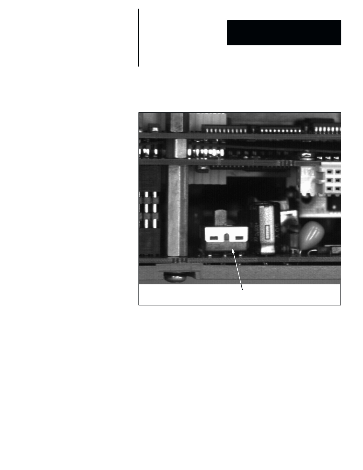
Use the following steps to set the DC voltage selection switch on the CVIM2
module:
1. Locate the DC voltage selection switch on the back of the CVIM2
module. Refer to Figure 1.1 (page 1–3).
2. Set the switch as shown in Figure 1.1 (the 12V setting) for applications
using three or fewer cameras.
3. Set the switch to the 24V position for applications using more than three
cameras, or using any of cameras #4, #5, or #6.
1–2
Page 15
Chapter 1
Chapter
Hardware Connection and Powerup Check
5
4. Install the CVIM2 module in the chassis. Tighten the thumbscrews
alternately until the module is fully seated in the chassis.
Figure 1.1 CVIM2 Module (back view): DC V oltage Selection Switch
DC Voltage selection switch
(shown in internal source position)
Installing the Optional DC Power Supply Cable
If your application requires an external +24VDC power supply, you can use
one of two Allen–Bradley DC power supply cables to connect the external
+24VDC power supply to the Pyramid Integrator chassis power supply. The
power supply must have sufficient capacity to power all of the cameras.
These are the Allen–Bradley DC power supply cables:
• Catalog No. 5120–CP3 –– for applications not requiring a fan chassis (for
cooling the Pyramid Integrator chassis power supply).
• Catalog No. 5120–CP2 –– for applications using the eight–slot chassis
and requiring a fan chassis.
Note that each cable has a set of four color–coded leads terminated with
spade lugs.
1–3
Page 16

Chapter 1
Hardware Connection and Powerup Check
Attach the color–coded leads on the DC cable to the external DC power
supply as follows:
1. Connect the triple red leads to the DC power supply’s main “+ output”
terminal.
2. If your DC power supply has a “+ sense” terminal, connect the single red
lead to that terminal. Otherwise, connect the single red lead to the “+
output” terminal, along with the triple red leads.
3. Connect the triple black leads to the DC power supply’s main “– output”
terminal.
4. If your DC power supply has a “– sense” terminal, connect the single
black lead to that terminal. Otherwise, connect the single black lead to
the “– output” terminal, along with the triple black leads.
5. Connect the molded plug on the other end of the DC power supply cable
to the Pyramid Integrator power supply front panel jack labeled “Fan
Chassis.”
6. If your application has a fan chassis and you are using the 5120–CP2
cable, connect the smaller molded plug to the jack in the fan chassis.
Finally, attach a line cord or other AC power supply cables to the DC power
supply, as appropriate for your installation.
NOTE: Do not apply AC power to the DC power supply yet.
1–4
Page 17
ММММММММ
ММММММММ
1771 CHASSIS
Ì
Ì
Ì
P
L
C
REMOTE I/O LINK
MACHINE VISION
CAMERA 6
MACHINE VISION
CAMERA 1
MACHINE VISION CAMERAS
2801–YB
2801–YD
2801–YE
CABLES CABLES
2801–NC5 (5M)
2801–NC6 (10M)
2801–NC7 (25M)
RS – 232
SERIAL COMMUNICATIONS
2801–YC
2801–NC14 (5M)
2801–NC15
(10M)
2801–NC16
(25M)
Chapter 1
Chapter
Hardware Connection and Powerup Check
5
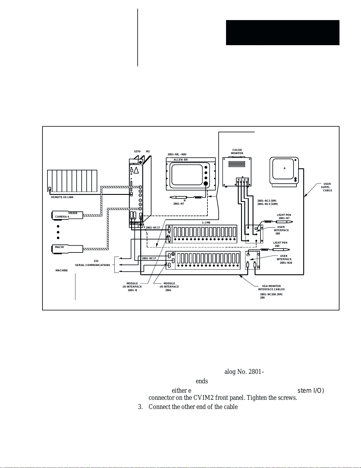
Connecting the I/O and Camera Cables
Refer to the CVIM2 interconnect diagram (Figure 1.2) for the I/O and
camera cable connections in the next steps.
Figure 1.2 CVIM2 Interconnect Diagram for I/O Cables
MONITOR INTERFACE
CABLES
2801–NC19A (5M)
2801–NC19B (10M)
5370–CVIM2
MODULE
I/O INTERFACE
2801–N21
2801–NC17
2801–NC17
2801–N8, –N8V
ALLEN–BRADLEY
LIGHT PEN
2801–N7
MODULE
I/O INTERFACE
2801–N27
2801–JMB
2801–JMB
COLOR
MONITOR
RGB S
2801–NC19C (25M)
CABLES
2801–NC2 (5M)
2801–NC3 (10M)
LP
B
G
S
R
IN
VGA MONITOR
INTERFACE CABLES
2801–NC20A (5M)
2801–NC20B (10M)
2801–NC20C (25M)
VGA
LIGHT PEN
2801–N7
USER
INTERFACE
2801–N22
LIGHT PEN
2801–N7
USER
INTERFACE
2801–N26
USER
SUPPLIED
CABLE
Connecting the I/O Interface Cable (2801–NC17, –NC17A)
Use the following steps to connect the I/O interface cable to the I/O interface
module:
1. Locate the I/O interface cable, Catalog No. 2801–NC17 or –NC17A, and
the I/O interface module, Catalog No. 2801–N21 or –N27.
NOTE: The two ends of this cable are identical.
2. Connect either end of the cable to the Module I/O (or System I/O)
connector on the CVIM2 front panel. Tighten the screws.
3. Connect the other end of the cable to the CVIM connector on the I/O
interface module. Tighten the screws.
NOTE: The I/O interface cable can be connected directly from the CVIM2
module to I/O interface module 2801–N28 on the 2801–AM2 vision chassis.
1–5
Page 18

Chapter 1
Hardware Connection and Powerup Check
Connecting the User Interface Cable (2801–NC20A, B, C): VGA
Monitor
Use the following steps to connect the user interface cable when a VGA
monitor is to be used:
1. Locate the user interface cable, Catalog No. 2801–NC20A, B, or C, and
the user interface module, Catalog No. 2801–N26.
NOTE: The two ends of this cable are identical.
2. Connect either end of the cable to the User Interface connector on the
CVIM2 front panel. Tighten the screws.
3. Connect the other end of the cable to the CVIM2 connector on the user
interface module. Tighten the screws.
4. Connect the 15–pin connector on the VGA monitor cable to the VGA
MONITOR connector on the user interface module.
5. Connect the light pen, if used, to the LIGHT PEN socket on the user
interface module.
Connecting the User Interface Cable (2801–NC19A, B, C): N8 Monitor
Use the following steps to connect the user interface cable when an
Allen–Bradley 2801–N8 color monitor is to be used:
1. Locate the user interface cable, Catalog No. 2801–NC19A, B, or C.
2. Connect the 15–pin connector on the cable to the User Interface
connector on the CVIM2 front panel. Tighten the screws.
3. Connect the other end of the cable to the VIDEO INPUT connector on
the rear panel of the N8 color monitor.
4. Connect the light pen, if used, to the LIGHT PEN socket on the N8
monitor front panel.
Connecting the User Interface Cable (2801–NC19A, B, C): Other
RS–170 Monitors
Use the following steps to connect the user interface cable when a monitor
other than the Allen–Bradley 2801–N8 is to be used:
1. Locate the user interface cable, Catalog No. 2801–NC19A, B, or C, and
the user interface box, Catalog No. 2801–N22.
2. Connect the 15–pin connector on the cable to the User Interface
connector on the CVIM2 front panel. Tighten the screws.
3. Connect the other end of the cable to the INPUT connector on the N22
box.
4. Connect the light pen, if used, to the LIGHT PEN socket on the user
interface module.
1–6
Page 19

Chapter 1
Chapter
Hardware Connection and Powerup Check
5
5. Connect the coaxial cables to the appropriate R, G, B, and SYNC
connectors on the N22 module and the monitor.
Connecting the Camera Cable: 2801–YC Camera
Use the following steps to connect the appropriate camera cable when an
Allen–Bradley 2801–YC camera is to be used:
1. Locate the appropriate camera cable, Catalog No. 2801–NC14, 15, or 16.
2. Connect one connector on the cable to the appropriate Camera
connector on the CVIM2 front panel.
3. Connect the other connector on the cable to the appropriate connector on
the camera.
Connecting the Camera Cable: 2801–YB, –YD, and –YE Camera
Use the following steps to connect the appropriate camera cable when an
Allen–Bradley 2801–YB, –YD, or –YE camera is to be used:
1. Locate the appropriate camera cable, Catalog No. 2801–NC5, 6, or 7.
2. Connect the male connector on the cable to the appropriate Camera
connector on the CVIM2 front panel.
3. Connect the female connector on the cable to the appropriate connector
on the camera.
Connecting the Mouse Cable
Assuming that the I/O interface cable is attached to the Module I/O or
System I/O connector on the CVIM2 front panel, connect the mouse cable
to the PORT B connector on I/O interface box 2801–N27.
If you intend to use the PORT A connector, you must use a gender adapter
between the mouse cable connector and the PORT A connector on the I/O
interface box.
NOTE: You may need to configure the CVIM2 system to recognize the
selected mouse port connection. The mouse configuration procedure is
detailed in the Configuring CVIM2 System for Mouse Operation section on
page 1–10.
1–7
Page 20

Chapter 1
Hardware Connection and Powerup Check
Powering Up CVIM2 System
At this point, with all basic system components connected, the CVIM2
system is ready for the powerup check.
Use the following steps to perform the powerup check:
1. Set the video monitor brightness and contrast controls to their midrange
point or other appropriate preliminary point.
CAUTION: Verify that the AC voltage source is within
limits for both the video monitor and the CVIM2 system.
2. Set the scan mode, if available on your monitor, to “under scan.”
3. Set the power switch to “off.”
4. Insert the monitor AC line cord into the AC power outlet.
5. Set the power switch to “on.”
6. Attach the CVIM2 system AC line cord or cable to the AC power outlet
or source.
7. If your system is using an external +24VDC power supply, attach the AC
line cord or cable to the AC power outlet or source.
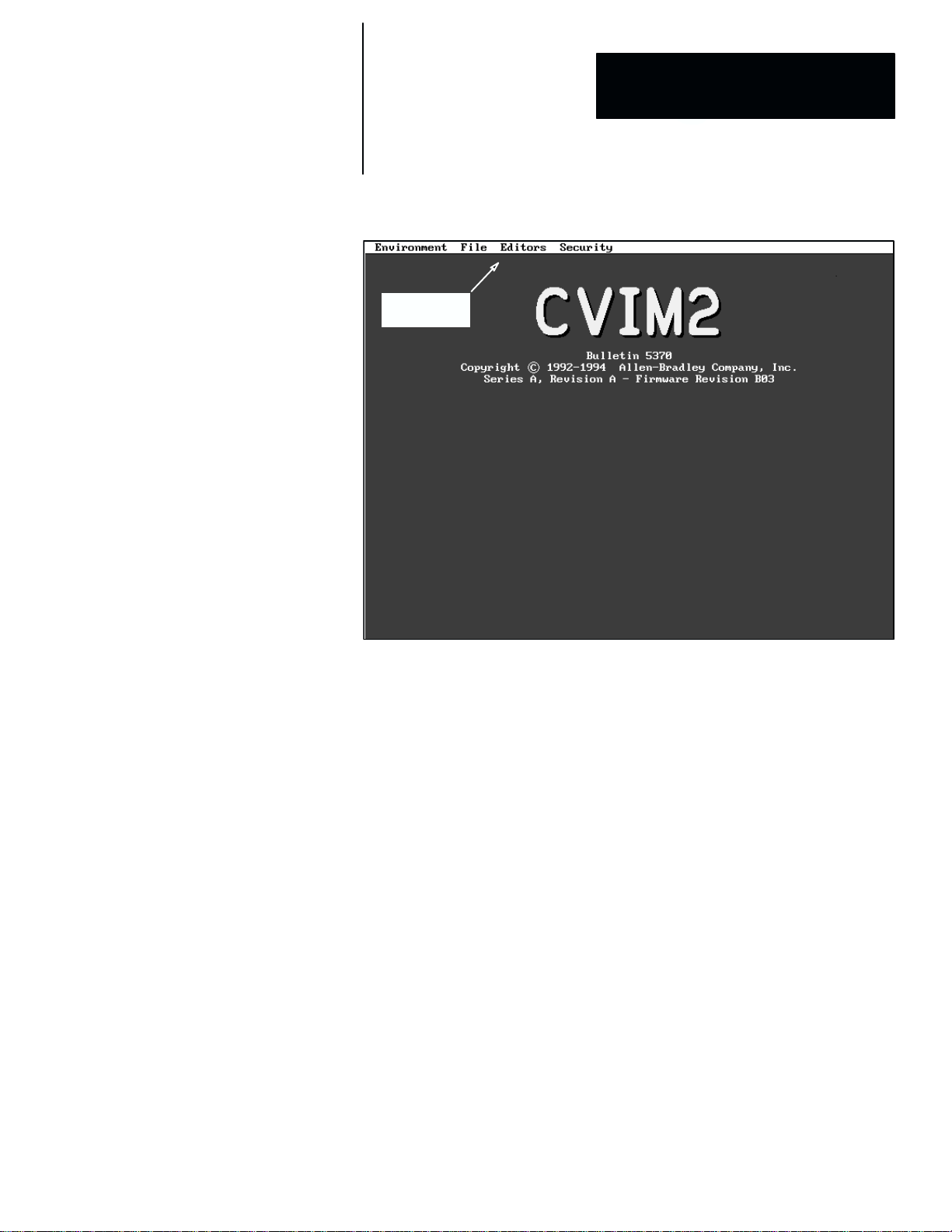
8. Set the power switch to On. When you do, you should see the following
results:
• The DC OK light on the chassis power supply should turn on.
• All LEDs on the CVIM2 front panel should light momentarily, after
which the Pass/Fail LED should remain green.
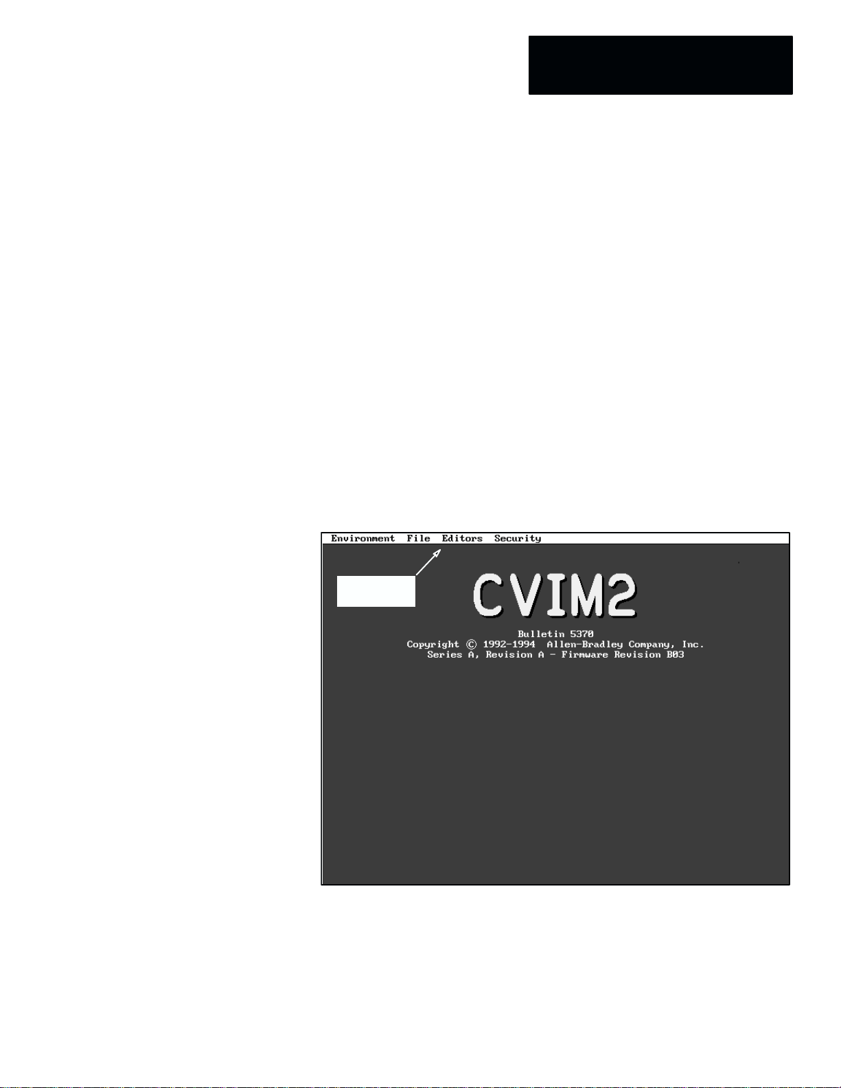
• In about five seconds, the banner message should appear on the
monitor screen, similar to the screen shown in Figure 1.3 (page
1–9).
9. Verify that the light pen operates properly by moving it across the screen.
The cursor pointer should follow the light pen’s movement. If it does not,
verify that the DC voltage selection switch setting shown in Figure 1.1
(page 1–3) is set correctly for your application.
10. Verify that the light pen switch operates by picking one or more of the
items on the main menu. In each case, a pull–down menu should appear.
11. If a mouse is connected to PORT A or PORT B on the I/O interface
box, check the mouse for proper operation by moving it across a table
top. The mouse pointer should follow the mouse’s movement. If not,
refer to the Configuring CVIM2 System for Mouse Operation section on
page 1–10.
1–8
Page 21
Chapter 1
Chapter
Hardware Connection and Powerup Check
5
Figure 1.3 Example: Monitor Screen After Normal Powerup
Main menu
bar
If you have not yet installed the CVIM2 system at its factory–floor site, refer
to the following Allen–Bradley manuals:
• Pyramid Integrator Installation Manual, Publication 5000–6.2.10.
• Grounding and Wiring Guidelines, Publication No. 1777–4.1.
• Solid–State Control Safety Guidelines, Publication No. SGI–1.1.
These manuals contain all the information required for panel– or
rack–mounting, electrical grounding, and connecting to the I/O components.
You will have already performed in this chapter some of the steps described
in the PI installation manual. When you encounter one of those steps, verify
that you have performed it correctly, then continue.
1–9
Page 22

Chapter 1
Hardware Connection and Powerup Check
Configuring CVIM2 System For Mouse Operation
The CVIM2 system supports most serial mouse and trackball pointing
devices that are IBM PC compatible. The following devices have been
tested and have been found to work with the CVIM2 system:
• Logictech Model C7–3F–9F
• Logictech Model CC–93–9F
• Microsoft Model LR 87483
• Mouse Systems Model 900800–001/A
• Clix Model CX–30
• Interlink Electronics Durapoint (exceeds NEMA 4X, 6P, and 13)
• Mouse Systems Model TP–305 (trackball)
After you power up the CVIM2 module, if the mouse pointer will not “track”
the mouse as you move it across a table top or other flat surface, and you are
using one of the above–listed devices, use the light pen to examine the
current serial communication port configuration and reconfigure, if
necessary, the specific port that you intend to use for mouse operation.
NOTE: When a port is configured for mouse operation, it cannot be used
for other data communication purposes.
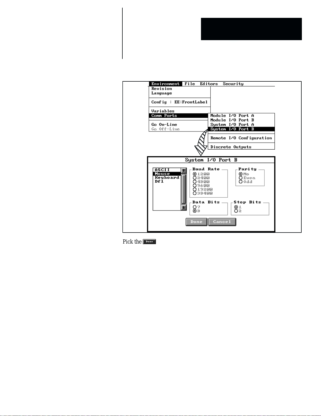
To configure a serial communication port for mouse operation, use the light
pen to pick Environment in the main menu bar. When the Environment
menu appears, pick Comm Ports. When you do, the Comm Ports menu
appears, as illustrated by the example in Figure 1.4 (page 1–11).
In the example, it is assumed that the mouse is connected to PORT B of the
I/O interface box and the I/O interface cable is connected to the System I/O
connector on the CVIM2 front panel. In this case, you would pick System
I/O Port B in the Comm Ports menu.
When you pick System I/O Port B, the System I/O Port B setup table
appears, as shown in Figure 1.4. When you then pick Mouse in the small
scrolling list, the appropriate mouse settings for baud rate, parity, data bit,
and stop bit parameters in the setup table “lock” at the values shown in the
figure.
1–10
Page 23
Chapter 1
Chapter
Hardware Connection and Powerup Check
5
Figure 1.4 Example: Setting System I/O Port B to Mouse Function
Pick the button to save the port selections and exit the port setup table,
then perform these steps to check mouse operation:
• Verify that the mouse operates properly by moving it across a table top.
The mouse pointer should follow the mouse’s movement.
If the mouse pointer does not move at this time, cycle the CVIM2 power
off (for at least five seconds), then on, to enable mouse pointer operation.
• Verify that the mouse buttons operate by picking one or more of the items
on the main menu, using the left button. In each case, a pull–down menu
should appear.
(Note that the center mouse button can perform some of the functions of
the left button, for example, picking and dragging a panel across the
screen, selecting alternate panel sizes, and operating the scrolling
functions. The right button can alternately position a panel over or under
an overlapping panel.)
For more information about mouse operations, refer to the Screen Pointer
Functions section of Chapter 2, CVIM2 System Configuration: An Overview,
starting on page 2–9.
1–11
Page 24
Chapter
2
CVIM2 System Configuration: An Overview
This chapter discusses the basic phases of system configuration and the
major configuration functions in each phase. The details of the inspection
configuration process are provided in Chapter 3, Image Acquisition
Parameters, and Chapter 4, Inspection Configuration.
The discussions that follow assume that all CVIM2 system parameters are set
to their out–of–box default state. They also assume that you are already
familiar with the CVIM2 user interface and with using the light pen and/or
mouse to “navigate” the user interface.
After System Powerup
After a normal powerup, the monitor screen displays the CVIM2 “banner
message,” as shown in Figure 2.1.
Figure 2.1 Example: Monitor Screen After Normal Powerup
Main menu
bar
Note that the banner message indicates the current series and firmware
revision levels of the CVIM2 system. Along the top margin is the main menu
bar.
2–1
Page 25
Chapter 2
CVIM2 System Configuration: An Overview
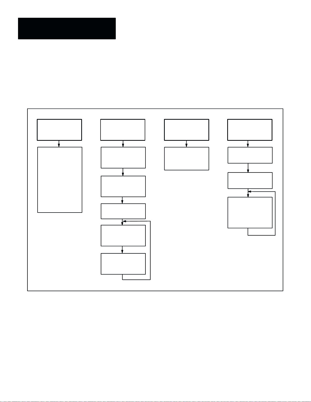
CVIM2 Configuration: Four Basic Phases
Phase 1
Select
configuration
names
Configuration
File Editor:
Enter configuration
file name
Enter acquisition
configuration
file name
Enter discrete I/O
file name
*Enter message
file name
Figure 2.2 is a chart showing four basic phases that are involved in
configuring the CVIM2 system for a typical inspection application. Many
details are intentionally omitted in order to emphasize the overall picture of
the system configuration process.
Figure 2.2 Basic Phases of CVIM2 System Configuration
Phase 2 Phase 3 Phase 4
Configure
inspection
Configuration Editor:
Enter inspection
names
Acquisition Editor:
Select image
acquisition parameters
Pick Setup to enter
toolset editor
Select tool names,
and configure all
inspection tools
Select
discrete I/O
parameters
Discrete I/O Editor:
Name I/O signals, and
assign input and output
functions
Begin online
inspection
operations
Main menu bar:
Pick Environment
Environment menu:
Pick On–Line
Observe and evaluate
inspection operation
and tool results
Adjust tools if
necessary
Evaluate tool
operation offline
in setup mode
*Refer to the CVIM2 Communications Manual, Pub. No. 5370–804, for details.
2–2
Page 26
Chapter 2
Chapter
CVIM2 System Configuration: An Overview
5
Major Configuration Functions
The remainder of this chapter describes the major configuration functions
within each basic phase of the CVIM2 system configuration identified by the
chart in Figure 2.2 (page 2–2).
Selecting Configuration File Names
Definition: A configuration file stores information about an inspection
application, such as the names of the toolsets and the number of image
buffers used.
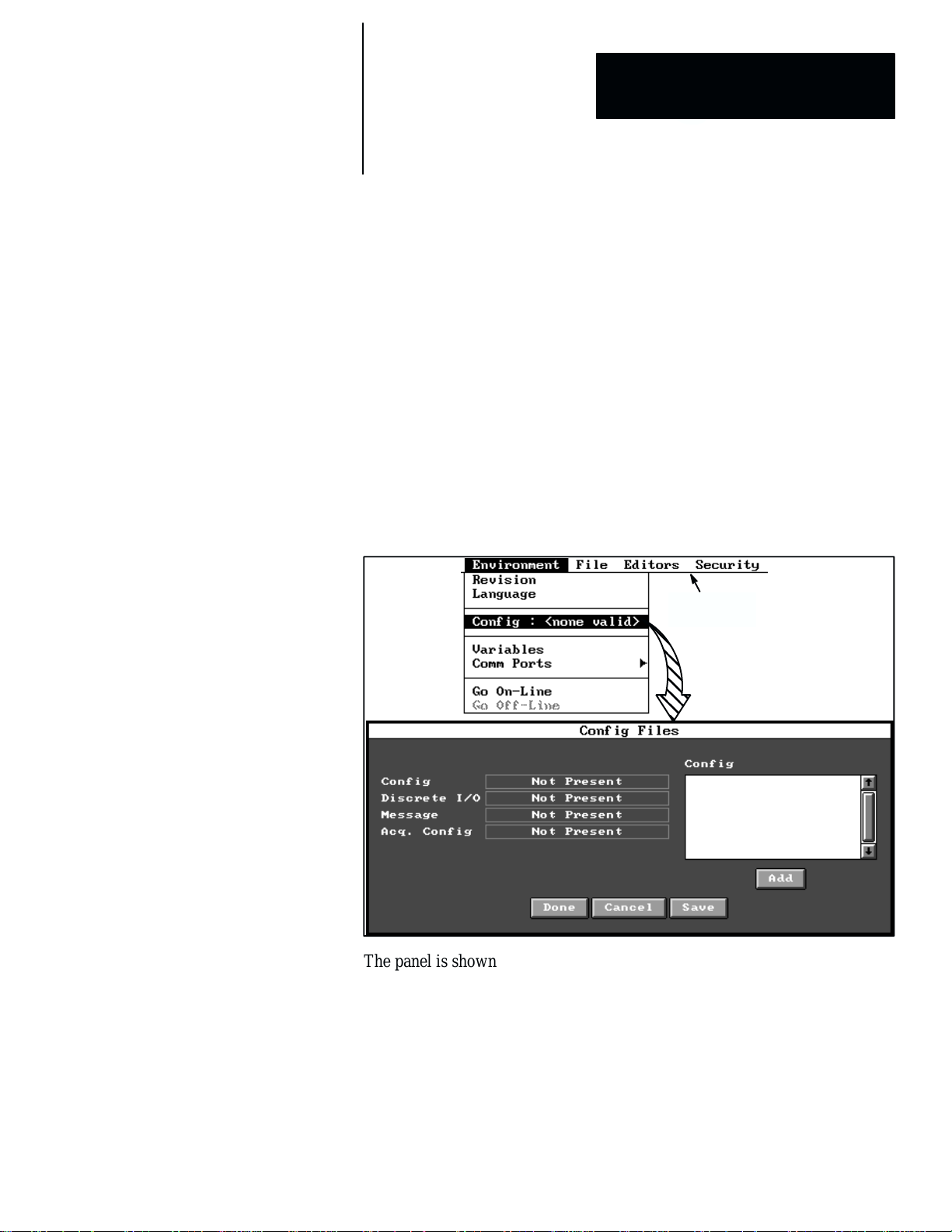
The first step in Figure 2.2 is taken from the Config Files panel. You can
access this panel from Environment in the main menu bar. When you pick
Config in the Environment menu, the Config Files panel appears, as shown
in Figure 2.3.
Figure 2.3 Initial Appearance of Config Files Panel
Main menu
bar
The panel is shown in its initial state, before any configuration files have
been defined. At this time, you must enter an appropriate name in the Config
and Acq. Config fields in order to continue with the configuration process.
NOTE: You can add the Discrete I/O name and/or Message name at this
time, or later. (Note that to access the Discrete I/O and Communications
Editor panels, however, you must first enter names for these panels in the
Config Files panel.)
2–3
Page 27
Chapter 2
CVIM2 System Configuration: An Overview
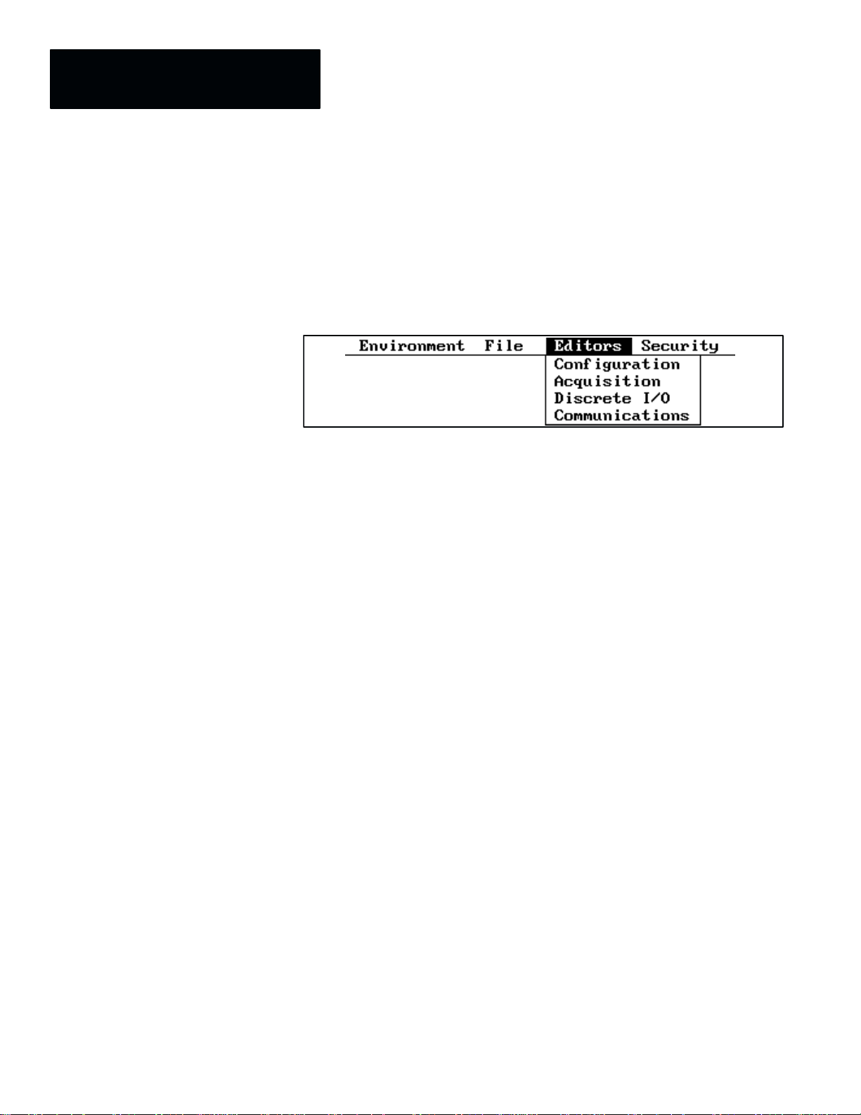
Picking the Editors Menu
The next step, after defining at least one configuration, is taken from the
Configuration Editor panel. You can access this panel from Editors in the
main menu bar. When you pick Editors, the Editors pulldown menu appears,
as shown in Figure 2.4.
Figure 2.4 The Editors Pulldown Menu
Note also that you have four choices: Configuration, Acquisition, Discrete
I/O, and Communications. Briefly, this is what they mean:
• Configuration –– Use this editor to define one or more sets of inspection
tools for your application.
• Acquisition –– Use this editor to select the camera types, numbers of
cameras, trigger sources for acquiring camera images, and other
parameters relating to the acquisition of images.
• Discrete I/O –– Use this editor to assign signals and select parameters for
discrete inputs and outputs.
• Communications –– Use this editor to create messages for data
communications using serial I/O ports or the remote I/O port.
2–4
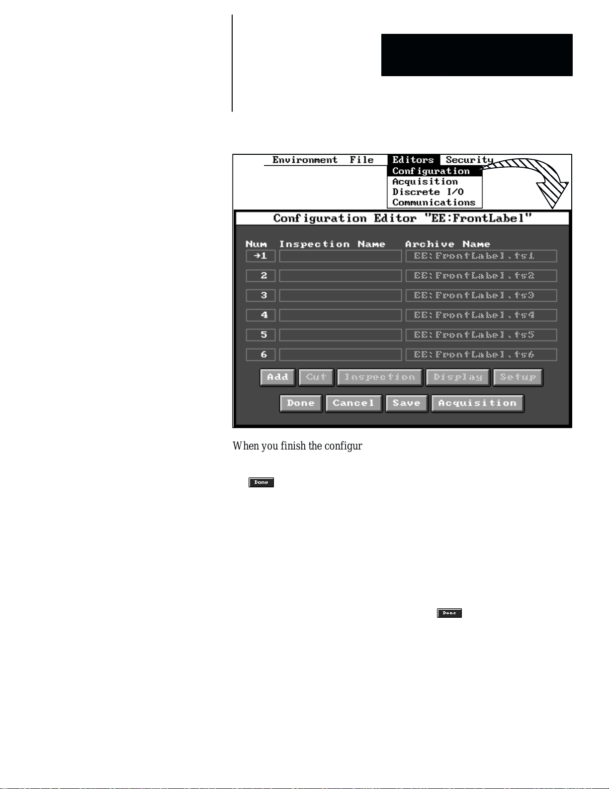
Selecting Configuration Parameters
When you pick Configuration, the Configuration Editor panel appears, as
shown in the example in Figure 2.5 (page 2–5).
The purpose of the Configuration Editor panel is to set up all of the
inspection application requirements for a single configuration file. Using this
panel, you can select the toolsets (up to six for one configuration file),
configure all of the inspection tools, set various acquisition and inspection
parameters, and perform the initial (“setup mode”) evaluations of the tools’
performance.
The CVIM2 system enters various default names for the toolsets (under the
“Inspection Name” heading and the “Archive Name” heading); however,
you can easily change any of these names to suit your inspection application.
Page 28
Chapter 2
Chapter
CVIM2 System Configuration: An Overview
5
Figure 2.5 Example: Configuration Editor Panel With Six Inspections
When you finish the configuration of at least one toolset (and also select the
image acquisition parameters, as described in the next section), you can exit
the Configuration Editor panel and return to the main menu bar by picking
the
When you place the CVIM2 system online, the system executes the currently
selected configuration file. If the system is powered down, then powered up
again, it will automatically begin online operations using the last selected
configuration file –– in this example, it would use the “FrontLabel”
configuration file.
The CVIM2 system can store multiple configuration files in the CVIM2
system’s memory; thus, you can easily change inspection applications by
accessing the Config Files panel, highlighting (picking) another Config file
name listed in that panel, and then picking the
When you return to the Configuration Editor panel, the newly selected
configuration file name will appear in the title bar of that panel.
button.
button.
2–5
Page 29
Chapter 2
CVIM2 System Configuration: An Overview
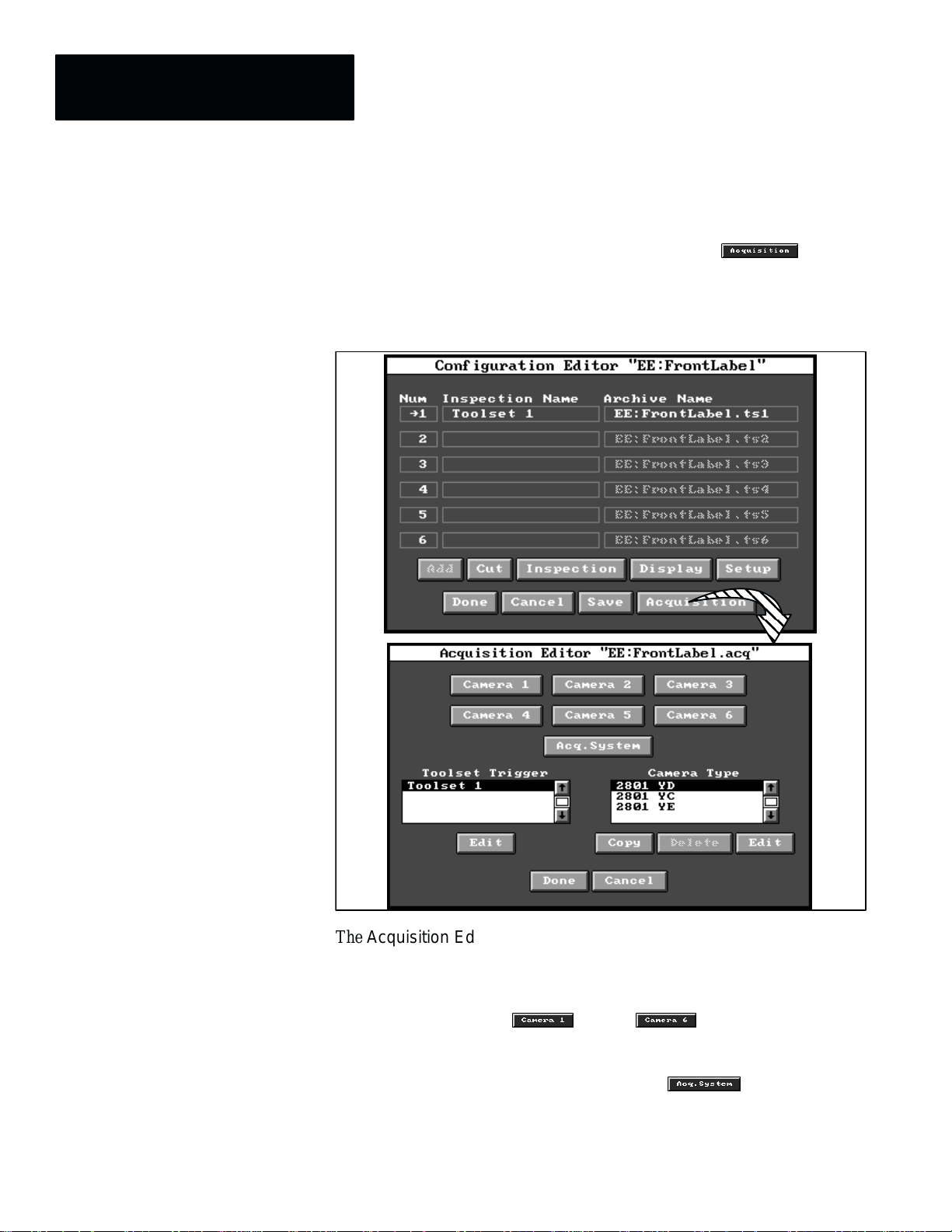
Selecting Image Acquisition Parameters
Your next step, after configuring a toolset, is to pick the button in
the Configuration Editor panel. When you pick this button, the Acquisition
Editor panel appears, as shown in the example in Figure 2.6.
Figure 2.6 Example: The Acquisition Editor Panel
2–6
The Acquisition Editor panel provides access to all of the parameters and
settings that the system uses to acquire an image for an inspection. The panel
contains two scrolling lists and several buttons, which are described briefly
as follows:
• Camera 1 – 6 –– The through buttons access the
corresponding Camera setup panels, from which you can perform focus
adjustments, light reference adjustments, and other related functions.
• Acquisition Systems Settings panel –– The button accesses
the Acquisition System Settings panel, from which you can select a
default camera enable synchronizing the CVIM2 system with external
devices or another CVIM2 system, and/or selecting parameters for
switching between camera banks 1 – 3 and 4 – 6.
Page 30
Chapter 2
Chapter
CVIM2 System Configuration: An Overview
5
• Toolset Trigger panel –– This scrolling list panel enables you to select a
Toolset Trigger edit panel, from which you can edit various trigger
parameters for a particular toolset. The adjacent button selects the
Toolset Trigger edit panel for the highlighted toolset trigger.
• Camera Type panel –– This scrolling list panel enables you to select a
Camera Type edit panel, from which you can edit various timing
parameters for a particular camera type. The adjacent
selects the Camera Type edit panel for the highlighted camera type. The
button selects the highlighted camera type for the purpose of
creating a non–standard camera type and editing its parameters. The
button deletes the highlighted camera type (non–standard only).
When you finish selecting the image acquisition parameters, you can exit the
Acquisition Editor panel and return to the Configuration Editor panel by
picking the
button.
button
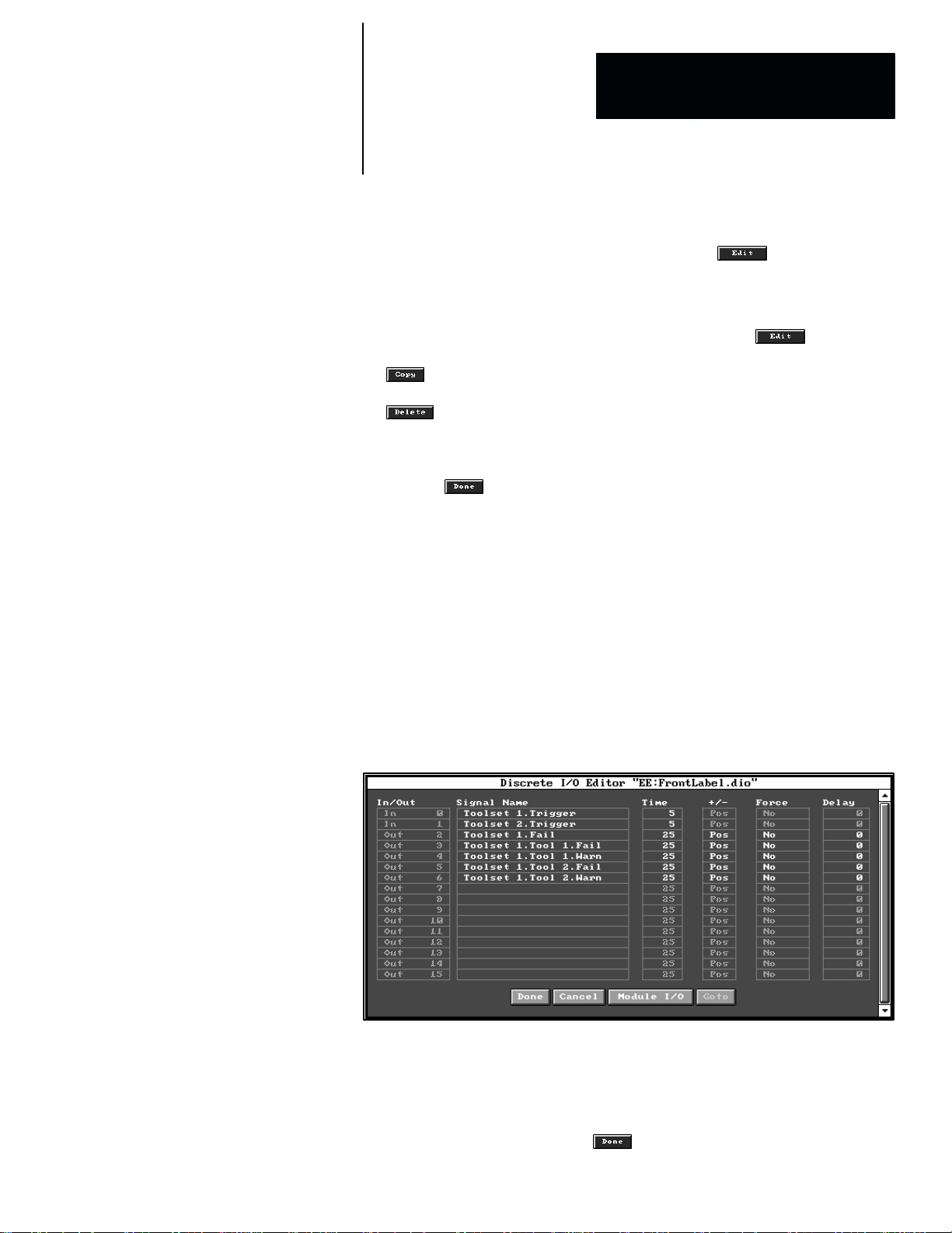
Selecting Discrete I/O Parameters
After configuring a toolset and selecting acquisition parameters, your next
step is to pick Discrete I/O in the Editors menu. You can then select and
configure the discrete inputs and outputs to be used in your application.
When you pick Discrete I/O, the Discrete I/O Editor panel appears, as
shown in the example in Figure 2.7, provided that you have added a discrete
I/O file name in the Config Files panel, as noted on page 2–3.
Figure 2.7 Example: The Discrete I/O Editor Panel
The purpose of the Discrete I/O Editor panel is to configure the trigger
inputs and assign functions to the outputs as required for a particular
application. Using this panel, you can assign signals to the trigger inputs and
specify the minimum trigger signal pulse duration, and you can assign a
specific function to each output, such as toolset failure, tool warning, and so
on. When you finish, picking the
button returns to the main menu bar.
2–7
Page 31
Chapter 2
CVIM2 System Configuration: An Overview
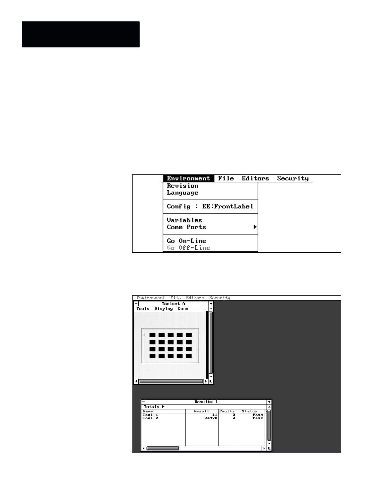
Selecting Online Operation
Normally, your last step is to pick Go On–Line in the Environment menu.
This enables the system to perform online inspection operations, which will
begin immediately if the selected trigger source is active. During online
operations, you can observe the camera image and inspection tool display
and the inspection results data display at the same time.
When you pick Environment, the Environment menu appears, as shown in
the example in Figure 2.8.
Figure 2.8 Example: The Environment Menu
When you pick Go On–Line, the system displays the camera image and
tools, and the inspection results data. Figure 2.9 shows an example of this.
Figure 2.9 Example: Online Screen Display
2–8
Page 32

Chapter 2
Chapter
CVIM2 System Configuration: An Overview
5
The display panel shows the inspection tools over the inspected image. The
menu bar in the display panel enables you to access these tools for the
purpose of making minor adjustments, and for assigning “freeze” modes,
which allow analysis of images in which one or more tools have failed their
inspection tasks.
The results panel displays the basic inspection results for each tool listed;
namely, the pass/fail status, the accumulated number of faults, and the
numerical inspection result. The “Totals” item in the menu bar accesses
additional results data, such as the number of missed triggers and various
inspection timing data.
Screen Pointer Functions
Major Pointer Function
Select or pick item
(menu item, button, selector)
Drag
(tool, tool end, panel, panel
corner)
The CVIM2 system uses a light pen and/or mouse to perform numerous
screen pointer functions such as selecting menus and menu items, picking
and placing tools, and positioning and sizing panels. Most of these functions
are performed by positioning a screen pointer over an item on the screen and
pressing the light pen tip against the screen, or “clicking” the left mouse
button (that is, pressing and releasing the button quickly), if a mouse is used.
Light Pen and Mouse Operation
The light pen and mouse can perform the same screen pointer functions, but
they differ in the method of performing those functions. Table 2.1 identifies
the major differences in the operation of these two screen pointer systems.
Table 2.1 Comparison of Light Pen and Mouse Operation
Mouse Light Pen
Position the pointer over an item on the
screen, then press and release (“click”) the
left button. The item under the pointer when
the button is released is the one selected.
Position the pointer over an item, then press
and hold the left button while dragging the
item across screen.
Release the button when the item is at its
final position.
Position light pen tip over item on screen,
then press and release light pen tip against
screen
Position the light pen tip over an item on
screen and press the tip against the screen
until a cross (+) symbol appears.
Release the light pen tip from the screen,
then drag the item across screen. Press and
release the tip against screen when the item
is at its final position.
2–9
Page 33

Chapter 2
CVIM2 System Configuration: An Overview
NOTE: In the following discussions, the use of a mouse is assumed for the
screen pointer functions. Table 2.1 compares equivalent light pen and mouse
operation.
Figure 2.10 through Figure 2.12 (page 2–13) illustrate the screen pointer
functions.
Figure 2.10 demonstrates a sequence of menu item and button picks, starting
at “Editor” in the main menu bar. In this figure, the pointer is positioned over
Editor in the main menu bar, and the left button is clicked, in order to select
the Editor menu. The pointer is then positioned over Configuration in the
Editor menu, and the left button is clicked, in order to select the
Configuration Editor panel.
Figure 2.10 Example: Sequence of Menu and Panel Selections
Pick
Pick
2–10
Pick
Page 34

Chapter 2
Chapter
CVIM2 System Configuration: An Overview
5
In the Configuration Editor panel, the pointer is positioned over the
button, and the left mouse button is clicked, to select the
Inspection panel. When the appropriate inspection parameters are entered,
the pointer is placed over the
clicked, to exit back to the Configuration Editor panel.
Figure 2.11 (page 2–12) demonstrates dragging a panel to a different position
on the screen. The pointer can be placed anywhere in the title bar and the
panel dragged to its final position.
Figure 2.12 (page 2–13) uses a “Results” panel to identify the symbols and
points that are used for manipulating a panel on the screen (some of these
points and symbols are also used on other panels). When picked, they
perform specific functions, as follows:
• Expand/contract size symbol –– If you pick this symbol (♦) in the
upper right corner, the panel will change to an alternate size (by default, it
expands to the full screen size initially). When you pick the symbol again,
the panel returns to its previous size.
• Change panel size symbol –– You can change the panel size (without
moving the panel) by picking and dragging this symbol in the lower right
corner of the panel. The panel’s upper left corner remains anchored.
• Move panel –– You can move the panel (without changing its size) by
picking anywhere in the title bar and dragging the panel across the screen.
(See Figure 2.12.)
• Display icon symbol –– If you pick this symbol (*) while the panel is
displayed on the screen (expanded or reduced), it will contract into the
icon form. When you pick the icon, the panel returns.
• Scroll bar and arrows –– When the panel is not high enough to display
all rows listed in it, you can pick the up or down arrows or the scroll bar
on the right side of the panel to scroll panel contents up or down.
Similarly, when the panel is not wide enough to display all of its columns,
you can pick the left and right arrows or the scroll bar on the bottom of
the panel to scroll the panel’s contents right or left.
button, and the left mouse button is
Center Button and Right Button
The center mouse button can perform some of the functions of the left
button, for example, picking and dragging a panel across the screen, selecting
alternate panel sizes, and operating the scrolling functions. The right button
can alternately position a panel over or under an overlapping panel.
2–11
Page 35

Chapter 2
CVIM2 System Configuration: An Overview
Figure 2.11 Example: Moving a Panel Across the Screen
Drag panel
2–12
Final position
of panel
Page 36

Pick to
change panel
to icon form
Chapter 2
Chapter
CVIM2 System Configuration: An Overview
Figure 2.12 Example: Panel Manipulation Functions
5
bar to drag entire results
Pick here to select
“Totals” detail panel
Pick scroll arrows and
bar to scroll columns
Pick anywhere in title
panel across screen
Pick here to
select “Results”
detail panel
Pick to select
alternate panel size
Pick scroll
arrows and bar
to scroll rows
Pick and drag to
change panel size
2–13
Page 37

Chapter 2
CVIM2 System Configuration: An Overview
Keyboard Functions
Throughout the configuration process, names must be entered for files,
inspections, tools, and various other items. At each point where a name is
required, a standard keyboard panel appears on the screen, as illustrated in
Figure 2.13.
Figure 2.13 Example: The Keyboard Panel (Lowercase)
Lowercase (default)
Note that the printable characters appear in lowercase by default.
Most of the keys are straightforward in their operation; that is, their functions
are analogous to the keys on a computer keyboard. When you pick any
printable character, it appears in the name bar immediately above the keys:
The character in the key cap is the one that will appear in the name bar. The
maximum number of characters that you can enter depends on the context.
Here is a brief description of the keys:
• Alphanumeric keys –– These are the printable characters, and include
lowercase and uppercase alpha characters, digits, and punctuation
characters.
• Tab key –– This key moves the cursor four places to the right of the
previous tab stop.
• Left and right arrow keys –– These keys move the cursor one place to
the left or right.
• Home key –– This key returns the cursor to the leftmost position.
• End key –– This key moves the cursor one place to the right of the
rightmost character in the name bar.
• Ins (insert) key –– This key enables you to insert a character to the left of
the present cursor position. When you pick the insert key, and the
blinking cursor changes to a block (J), the insert mode is enabled. When
you pick the insert key, and the cursor changes to an underscore (Ċ), the
typeover mode is enabled.
2–14
Page 38

Chapter 2
Chapter
CVIM2 System Configuration: An Overview
5
• Del (delete) key –– This key deletes the character at the cursor position.
• Clear key –– This key clears all characters from the name bar.
• Cancel key –– This key exits the keyboard panel without saving any new
characters entered in the name bar.
• BkSp (backspace) key –– This key moves the cursor one place to the left
and deletes the character in that position.
• Enter key –– This key saves all new characters entered in the name bar
and exits the keyboard panel.
• Caps key –– This key changes the alpha characters between uppercase
and lowercase. The keyboard remains in the “caps” mode until you pick
the caps key again.
• Shift key –– This key changes all printable character between uppercase
and lowercase. (The default setting is lowercase.) The keyboard returns to
the lowercase mode when you pick one character.
• Special key –– This key changes the keyboard to a special set of printable
characters (lowercase only). The keyboard returns to the lowercase mode
when you pick one character.
Calculator Keypad Functions
Throughout the configuration process, numeric parameters must be entered.
At each point where such a parameter is required, a standard “calculator”
keypad panel appears on the screen, as illustrated in Figure 2.14.
Figure 2.14 Example: The Calculator Keypad Panel
Note that the calculator keypad appears in the decimal mode by default.
Most of the keys are straightforward in their operation; that is, their functions
are analogous to the keys on a hand held calculator. When you pick any digit,
2–15
Page 39

Chapter 2
CVIM2 System Configuration: An Overview
it appears in the display window above the keys. The maximum number of
digits that you can enter is 10.
Some keys appear in shaded type, which indicates that they are inactive in
the keypad’s current mode of operation. For example, when the decimal
mode is selected, the hexadecimal alpha keys are shaded.
Here is a brief description of the keys:
• Digit keys –– These keys enter numeric digits in the display window.
• Operator keys –– These keys perform mathematical operations on the
numbers entered in the display window: The (B) key performs a divide
operation; the () key performs a multiply operation; the ()) key
performs an addition operation; the (*) key performs a subtraction
operation, and the (%) key performs a percentage operation. The (+) key
completes the mathematical operation and displays the result in the
display window.
• Sign key –– The (") key changes the sign of the operand to minus (*) if
it is plus, or vice versa. (The plus sign is never displayed.)
• *Decimal key –– This key is active only when floating point values are
involved. At all other times the decimal (.) in the key appears in shaded
type, indicating that the key is inactive.
• Backspace (²) key –– This key moves the cursor one place to the left
and deletes the digit at that position.
• Clr (clear) key –– This key clears all digits from the display window.
• Base key –– This key selects the “base” of the numbering system to be
used: DEC for decimal (base 10), HEX for hexadecimal (base 16), BIN
for binary (base 2), or OCT for octal (base 8). The various bases appear in
succession when you pick this key repeatedly.
Note that the digit keys that are non–functional with each base appear in
shaded type; thus, all but digits 0 and 1 are shaded in the BIN mode.
• Orig (original) key –– This key restores the original contents of the
display window when the keypad first appeared.
• Esc (escape) key –– This key exits the keypad without altering the
original value that appeared in the display window.
• Done key –– This key saves any changes to the original value in the
display window and exits the keypad.
2–16
* The calculator operates in the integer mode for most operations, and all
fractional results from calculations are thus truncated. For example, the
result from 100 B 6 would appear in the calculator display window as 16,
not 16.6667. Some operations, however, such as a gage using the linear
measurement operation, use floating point numbers for inspection results.
The decimal key is active when you set range limits for those results. Thus,
the result from 100 B 6 would appear in the display window as 16.667 in
this case.
Page 40

Chapter
3
Image Acquisition Parameters
This chapter discusses the details of selecting the appropriate image
acquisition parameters in preparation for configuring the inspection tools.
NOTE: During the inspection configuration process, you would normally
access the image acquisition parameters through the
Configuration Editor panel (see Chapter 4, Inspection Configuration; page
4–7). However, you can also access these parameters from the main menu
bar through the Editors menu, as described in this chapter.
When you pick Acquisition in the Editors menu, the Acquisition Editor
panel appears, as shown by the example in Figure 3.1.
button in the
Figure 3.1 Example: Selecting the Acquisition Editor Panel
Main menu
bar
The Acquisition Editor panel provides access to all of the parameters and
settings that the system uses to acquire an image for an inspection. The panel
contains two scrolling lists and several buttons, which are described briefly
as follows:
• Camera 1 – 6 –– The through buttons access the
corresponding Camera setup panels, from which you can perform focus
adjustments, light reference adjustments, and other related functions.
3–1
Page 41

Chapter 3
Image Acquisition Parameters
• Acquisition Systems Settings panel –– The button accesses
the Acquisition System Settings panel, from which you can select a
default camera, enable synchronizing the CVIM2 system with external
devices or another CVIM2 system, and/or select parameters for switching
between camera banks 1 – 3 and 4 – 6.
• Toolset Trigger panel –– This scrolling list enables you to edit various
trigger parameters for a particular toolset. The adjacent
selects the Toolset Trigger edit panel for the highlighted toolset trigger.
button
• Camera Type panel –– This scrolling list enables you to edit various
timing parameters for a particular camera type. The adjacent
button selects the Camera Type edit panel for the highlighted camera
type. The button selects the highlighted camera type for the purpose
of creating a non–standard camera type and editing its parameters. The
button deletes the highlighted camera type (non–standard only).
The following sections provide detailed information about all of the items
listed above.
Camera Setup Panel
When you pick one of the
through buttons in the
Acquisition Editor panel, a Camera setup panel for the selected camera
number appears, as shown by the Camera “Camera 1” panel in Figure 3.2.
Figure 3.2 Example: Selecting Camera Setup Panel for Camera 1
3–2
Page 42

Chapter 3
Chapter
Image Acquisition Parameters
5
The Camera setup panel contains a scrolling list panel, several parameter
selection boxes, and several buttons, which are described briefly as follows:
• Camera Type –– The Camera Type scrolling list enables you to select a
camera type (such as 2801–YF) that pertains only to the selected camera
number (this number corresponds to the camera port number on the
CVIM2 module front panel).
• Edit Camera Type –– The button accesses the Camera
Type edit panel for the camera type highlighted in the adjacent Camera
Type scrolling list. The Camera Type edit panel enables you to edit
various timing parameters for the highlighted camera type.
• H.Res –– This box selects either the full horizontal resolution capability
of the camera in use, or just half of that resolution capability.
• Fields –– This box selects one vertical field for half vertical resolution, or
two vertical fields for full vertical resolution.
• Focus Trigger –– This field selects either the internal trigger source or an
external trigger source for focus operations. It applies to the camera setup
operation only.
• Rate Per Minute –– This field selects a trigger rate per minute when the
auto/internal trigger source is selected as the focus trigger. It applies to
the camera setup operation only.
• Focus Source –– This field assigns a discrete input for the trigger signal
when the external trigger source is selected. It applies to the camera setup
operation only.
• Shutter Speed –– This field is active only when a frame reset camera
type (such as the 2801–YE) is selected. It accesses the calculator that is
used to set the frame reset camera’s shutter speed.
• Focus Strobe –– This assigns a discrete output for the strobe signal. It
applies to the camera setup operation only.
• Focus –– The button starts the focus function, which captures
continuous camera images and enables the user to perform camera and
lighting adjustments.
• Light Reference –– The button accesses the light
reference adjustment panel, which can be used to maximize the contrast
in the image.
• Light Probe –– The button accesses the light probe setup
function, which can be used to set up lighting compensation for the
inspection tools.
• Calibrate –– The button accesses the calibrate function, which
which enables you to calibrate the image field to inches or centimeters
(“world units”) and perform measurements, such as linear gaging, in
those units.
• Done –– The button exits the Camera panel and returns to the
Acquisition Editor panel.
The remainder of this section describes these functions, features, and
parameters in detail.
3–3
Page 43

Chapter 3
Image Acquisition Parameters
Camera Type Selection
This scrolling list panel lists the “standard” camera types that the
Allen–Bradley Company supports, along with any non–standard camera
types that have been user–configured in the Acquisition Editor panel. To
select a camera type for the current camera number, highlight the camera
type by picking its name.
You can edit various timing parameters for the highlighted camera type by
picking the
Type edit panel. (For details about this panel, refer to the Camera Type:
Selection and Editing section on page 3–33.)
button and accessing the corresponding Camera
Horizontal Resolution Selection
These are the two “H.Res”, or horizontal resolutions:
• Full –– This selects the full horizontal camera resolution equal to the
Acq. Pixels setting in the Camera Type panel (typically 512 pixels).
• Half –– This selects one half of the full horizontal camera resolution
(typically 256 pixels –– every other pixel is acquired).
Field Selections
The “Fields” selections are 1, First; 1, Same; and 2. Here is what they
signify:
• 1, First –– This causes the system to acquire the first field (odd or even)
to become available after any given trigger signal. The vertical resolution
is one–half the Acq. Lines (1/2 Lines) setting in the Camera Type
panel (typically 240 lines).
• *1, Same –– This causes the system to acquire field 0 only. The vertical
resolution is one–half the Acq. Lines (1/2 Lines) setting in the Camera
Type panel (typically 240 lines).
• *2 –– This causes the system to acquire the image with full vertical
resolution (typically 480 lines).
3–4
*These selections are significant only when an interlaced camera is used.
Page 44

Chapter 3
Chapter
Image Acquisition Parameters
5
Trigger/Rate/Source/Strobe Selections
These selections refer to the fields labeled Focus Trigger, Rate per Minute,
Focus Source I/O, and Focus Strobe I/O.
The description and procedures for making these selections and assignments
are the same as those described on page 3–45. The difference is that these
assignments apply only to the adjustment of the camera focus and lighting
resolution.
Shutter Speed Selection
The Shutter Speed field is active only when a frame reset camera type
(such as the 2801–YE), or a custom frame reset camera type, is selected. This
field enables access to the calculator pad, which is used to select a shutter
speed setting, in microseconds, for the 2801–YE (or other) frame reset
camera. The valid range for all cameras is 200 to 8000 microseconds.
Focus Function
When the auto/internal trigger source or a repeating external trigger source is
active, the focus function can capture a series of camera images, which
enables you to adjust the camera focus and aperture, and make the necessary
lighting and workpiece staging adjustments.
To enter the focus function, pick the button on the camera setup
panel. Figure 3.3 (page 3–6) illustrates the screen with the focus function
active.
NOTE: When using an external trigger source, if too much time elapses
between trigger pulses (about five seconds), system warning message #3072
appears on the display, as shown in Figure 3.4 (page 3–6). If you see this
message, you can either pick the
you can pick the button to re–enable the focus function (when you
expect a trigger signal to occur within five seconds).
When you are finished with the focus function, pick the
“Focus” box to return to the camera setup panel.
button to exit the focus function, or
button in the
3–5
Page 45

Chapter 3
Image Acquisition Parameters
Figure 3.3 Example: Camera Image With Focus Function Active
Figure 3.4 Trigger Time–out Warning Message
Light Reference Adjustment
The light reference adjustment function can be used to optimize the image
contrast.
NOTE 1: Adjust the light references before configuring any of the
inspection tools.
NOTE 2: Before adjusting the light references, be sure the lighting and the
camera focus and f–stop settings are optimized for your application.
3–6
Page 46

Chapter 3
Chapter
Image Acquisition Parameters
5
When you pick the button on the camera setup panel, the
camera image appears along with the adjustment cursors, as shown in
Figure 3.5.
Figure 3.5 Selecting Light Reference Adjustment
Inspected
object
(foreground)
The degree of contrast within any given image is a function of the difference
between the darkest and lightest pixels within that image. For example, if the
brightness level of the inspected object were 130 (on a scale of 0 to 255) and
the adjacent background were 165, the contrast difference between them may
not be sufficient to allow reliable inspection tool operations.
By adjusting the light reference appropriately, you can enhance the “natural”
image contrast by, in effect, expanding the existing narrow range
(130–to–165, in the preceding example) to a wider range such as 70 to 180,
thereby increasing the contrast and improving the inspection tool
performance.
Adjacent back-
ground
Your main objective in adjusting the light reference is to optimize the contrast
between the inspected part of the workpiece and the adjacent background.
3–7
Page 47

Chapter 3
Image Acquisition Parameters
Light Reference Settings
The light reference settings are adjusted by picking and dragging the left (Hi)
and right (Lo) cursors up or down, or by picking a point along the left or
right side of the slide bar. In the latter case, the cursor will jump to the
location of the light pen/mouse cursor.
The two references select high and low brightness values or “cutoff points”
that apply to all pixels within the image. They interact to affect the contrast
in the entire image. Individually, the reference settings have the following
effects:
• Hi reference setting –– The Hi reference has a value within a range of 1
to 255, where 1 is the lowest brightness in this range and 255 is the
highest. This setting determines the upper limit for the brightness of the
lightest pixels in the gray scale image. (Note that the lower limit is
bounded by the Lo reference setting; thus, if the Lo reference is set to
127, the Hi reference cannot be set lower than 128.)
Thus, any pixels in the image whose original brightness is higher (that is,
lighter) than the corresponding high reference will change to saturated
(255) white. (Note that during the adjustment these parts will appear
green, as explained later.)
• Lo reference setting –– The Lo reference has a value within a range of 0
to 254, where 0 is the lowest brightness in this range and 254 is the
highest. This setting determines the lower limit for the brightness of the
darkest pixels in the gray scale image. (Note that the upper limit is
bounded by the Hi reference setting; thus, if the Hi reference is set to 128,
the Lo reference cannot be set higher than 127.)
Thus, any pixels in the image whose brightness is lower (that is, darker)
than the corresponding low reference will change to saturated (0) black.
(Note that during the adjustment these parts will appear blue, as explained
later.)
3–8
You can see the high and low values in the boxes above and below the slide
bar. As you move each cursor up and down, the corresponding box displays
the changes in the value.
NOTE: The CVIM2 system acquires a new image every time you move a
light reference cursor. The trigger defined in the Setup Camera panel is
used for this purpose. Usually, the Auto camera trigger is used when setting
the light references; however, when using an external trigger source, if no
trigger pulse occurs within about five seconds after you attempt to move a
cursor, system warning message #3072 appears on the display, as shown in
Figure 3.4 (page 3–6). If you see this message, you can either pick the
button to discontinue the attempt to move the cursor, or you can
pick the button to try again (when you expect a trigger signal to occur
within five seconds).
Page 48

Chapter 3
Chapter
Image Acquisition Parameters
5
The interactive result of the two cursor settings is this: All portions of the
image whose brightness values are between the high and low light reference
values will have digitized pixel values between 0 and 255. Portions of the
image that are brighter than the high reference will have a digitized pixel
value of 255. Portions of the image that are darker than the low reference
will have a digitized pixel value of 0.
Here is a methodical approach to setting the two cursors for any application:
1. Drag the Hi cursor up to its highest position (value: 255).
2. Drag the Lo cursor down to its lowest position (value: 0).
3. Use the Focus function to optimize the focus and set the camera and
lighting for maximum brightness in an image of the parts to be inspected.
NOTE: If image saturation or “blooming” occurs, reduce the image
brightness by reducing the aperture, or, if practicable, by dimming the
lighting.
4. Drag the Hi cursor slowly downward until a green color begins to appear
in the brightest areas of the image. Then, drag the cursor gradually
upward until the green color just barely disappears from the image.
It is acceptable to let some portions of the image remain green (saturated
white) if they are not used for inspection.
5. Drag the Lo cursor slowly upward until a blue color begins to appear in
the darkest areas of the image. Then, drag the cursor gradually
downward until the blue color just barely disappears from the image.
It is acceptable to let some portions of the image remain blue (saturated
black) if they are not used for inspection.
At this point, the contrast between all inspection–related parts of the image
will be maximized. You may, however, still be able to improve the contrast
by making slight changes to the lighting, camera aperture setting, and light
references.
Figure 3.6 (page 3–10) provides an example of how a workpiece image
might appear before and after maximizing the contrast.
3–9
Page 49

Chapter 3
Image Acquisition Parameters
Figure 3.6 Example: Before and After Light Reference Adjustment
BEFORE:
AFTER:
3–10
Page 50

Chapter 3
Chapter
Image Acquisition Parameters
5
Light Probe Setup
The light probe tool provides a lighting compensation function, which
enables the CVIM2 system to adjust to changes in the brightness of the
image. One light probe is available for each camera.
The practical value of lighting compensation is its ability to adjust the light
reference automatically for each acquisition and obtain consistent images
over a range of lighting variations.
When you pick the
image appears with the light probe “box,” as shown in Figure 3.7.
Figure 3.7 Selecting Light Probe
button on the camera setup panel, the camera
Light probe
box
3–11
Page 51

Chapter 3
Image Acquisition Parameters
Light Probe Operation: General
The light probe tool is a small, special–purpose window or “box” that is
positioned during configuration over a user–designated light reference
“patch” somewhere in the top half of the image. Typically, the patch should
be near the top of the image, and always at least eight raster lines above the
highest tool. During inspection operations, the light probe measures the light
intensity reflected from the reference patch on a scale of 0 to 255 (0 is the
darkest light intensity and 255 is the brightest), and the CVIM2 system
calculates the average value of the pixels within the light probe.
The light probe is a pre–inspection tool. Thus, when the light intensity
changes from the original setting, the CVIM2 system uses the light probe’s
calculated value to modify gray scale values from the camera in order to
produce the best match to the original image. When the image is thus
compensated, the threshold and filter values for the inspection tools remain
valid.
Note that the calculated average value reflects the brightness of the reference
patch relative to the minimum and maximum values of 0 and 255. Therefore,
in order to ensure adequate light compensation flexibility, the light reference
patch should be a shade of gray that yields an initial value in the range of 160
to 200. This allows a margin for both an increase and a decrease in light
intensity.
The basic steps for configuring the light probe for use are these:
• If a suitable background area is not available in the field of view, prepare
a light– or medium–gray reference “patch” and position it within the
image using the Focus function.
• Enable the light probe for use by setting the Enabled/Disabled button to
Enabled.
• Position and “size” the light probe “box” over the reference area or
“patch” using the
(pick and place) button.
• Store the initial calculated average brightness of the pixels in the light
probe window, using the Nominal or “learn” function.
3–12
Page 52

Chapter 3
Chapter
Image Acquisition Parameters
5
Light Probe Panel
The Light Probe panel, shown in Figure 3.8, contains two fields and two
buttons: The Status field, which enables or disables the light probe tool, and
the Nominal field performs a “learn” operation, which causes the light probe
tool to acquire a sample or “nominal” luminance reading.
Figure 3.8 Light Probe Panel
Status –– The light probe status is indicated by the Status field in the Light
Probe panel. By default, the status is Disabled.
When you pick the Status field, the status toggles from Disabled to
Enabled, or vice versa, with the following effects:
• Disabled –– This indicates that the light probe for the associated camera
is inactive, and lighting compensation will not be provided.
• Enabled –– This means that the light probe for the associated camera is
active, and lighting compensation will be provided.
Nominal –– The nominal value is indicated by the Nominal field in the Light
Probe panel. When you pick the Nominal field, the light probe performs a
“learn” operation, during which it calculates the average luminance of the
pixels in the light probe box and displays the result in the Nominal field.
The
the
Light Probe “Tool Type” and Range Limits
Range limits can be selected for a light probe by selecting a Probe tool type
in the toolset edit panel, as shown in Figure 3.9 (page 3–14).
button enables you to position and “size” the light probe box, and
button exits the light probe setup and returns to the Camera panel.
When you pick Probe in the toolset edit panel, the Range panel appears, as
shown in Figure 3.9. Note that the nominal value (from the “learn” operation
described earlier) appears in the Range panel. Using the nominal value as
the basis for determining the appropriate range limits, select the range limits
as described in Chapter 7, Inspection Tools, on page 7–179.
3–13
Page 53

Chapter 3
Image Acquisition Parameters
Figure 3.9 Selecting Probe T ool Type and Range Limit Panel
Light Probe Tool Results and Math Tool Formulas
This section discusses the expanded inspection results that are available to a
math tool formula from a probe tool. Figure 3.10 illustrates the complete list
when the Statistics option is enabled for the light probe tool.
Figure 3.10 Expanded Results Lists For Light Probe T ools in Math Formulas
Execute
Pass
Warn
Fail
Total
Faults
Fail High
Warn High
Warn Low
Fail Low
Result
Samples
Min
Max
Sum
Sum2
3–14
Page 54

Chapter 3
Chapter
Image Acquisition Parameters
5
Here is a brief definition and explanation of each of the expanded result
types listed in Figure 3.10.
• Pass –– This returns a 1.000 when the tool has passed its inspection task,
and 0.000 for all other conditions.
• Warn –– This returns a “error code” when the tool is in a warn condition
(and not in a fail condition) and 0.000 for all other conditions. The error
code identifies a specific reason for the warning; for example, error code
1057.000 identifies “Low range warning” as the cause. The complete list
of error codes and warn conditions appears in Appendix A of this manual.
• Fail –– This returns a “error code” when the tool is in a fail condition and
0.000 for all other conditions. The error code identifies a specific reason
for the failure; for example, error code 1045.000 identifies “High range
fail” as the cause of the inspection failure. The complete list of error
codes and fail conditions appears in Appendix A of this manual.
• Fail High –– This returns a 1.000 when the inspection result from the
tool has exceeded the high Fail limit and 0.000 when the result has not
exceeded the high Fail limit.
• Warn High –– This returns a 1.000 when the inspection result from the
tool has exceeded the high Warn limit (and the tool is not in a fail
condition) and 0.000 when the result has not exceeded the high Warn
limit.
• Warn Low –– This returns a 1.000 when the inspection result from the
tool has exceeded the low Warn limit (and the tool is not in a fail
condition) and 0.000 when the result has not exceeded the low Warn
limit.
• Fail Low –– This returns a 1.000 when the inspection result from the
tool has exceeded the low Fail limit and 0.000 when the result has not
exceeded the low Fail limit.
• Result –– This returns the actual value of the light probe result; that is,
the luminance value from the light probe tool. This value corresponds to
the “learned” value that appears in the “Nominal” field of the Light
Probe panel. Light probe results can range from 0.000 (darkest) to
255.000 (lightest).
• *Samples –– This returns the current total number of inspection samples
since the start of run operation.
• *Min –– This returns the current minimum value of the inspection results
since the start of the run operation.
• *Max –– This returns the current maximum value of the inspection results
since the start of the run operation.
• *Sum –– This returns the current sum of all inspection results since the
start of the setup or online run operation.
• *Sum2 –– This returns the current sum of the squares of all inspection
results since the start of the setup or online run operation.
3–15
Page 55

Chapter 3
Image Acquisition Parameters
*These expanded statistical results are available only when a tool is enabled
for statistics operations, as indicated by Stats appearing in the Enabled
column for the corresponding tool.
Calibration Setup
This section discusses the calibrate function, which enables you to calibrate
the image field from each camera to inches, centimeters, or any other “world
units” of your choice, and perform linear gaging operations (such as linear
measure) in those units. Included in this discussion is a simple application
example whose main purpose is to demonstrate the procedure for using the
calibrate function.
The calibration function uses an X–axis and a Y–axis “gage” to detect the
edges across the X and Y axes of a calibration object, which is an object of
known dimensions. Each “gage” operates like a line gage performing a linear
measurement operation –– it returns a raw pixel count that you can then
calibrate to world units.
Calibration Applications
Calibration applies mainly to linear and circular gaging operations, using
linear measure, in applications that require uniform measurements of a
workpiece in the X– and Y–axes that are typically stated in “world units,”
such as inches and centimeters.
Other uses include applying the “scaling” values, which are derived from the
calibration operation, to a math tool formula set up to perform window area
measurements in world units.
Calibration: Basic Steps
Here is a summary of the basic calibration steps, listed in their normal order
of performance.
1. Set up calibration object image –– acquire a camera image of an object
of known dimensions to be used as the “calibration object” in the
calibration procedure.
2. Select calibrate function –– select the calibrate function in the
appropriate Camera setup panel.
3. Select calibration mode –– select the “Computed” or the “Absolute”
calibration mode.
3–16
Page 56

Chapter 3
Chapter
Image Acquisition Parameters
5
4. Enter scale factors –– For the Absolute calibration mode only, enter the
appropriate scale factors for each calibration gage.
5. “Pick and place” calibration gages –– For the Computed calibration
mode only, position the calibration gages over the workpiece image as
required. (For details, see Chapter 5, Pick and Place Functions.)
6. Set thresholds –– For the Computed calibration mode only, set the
threshold cursors to a point where the reference edges are optimized
along the X and Y calibration gages (For details, see Chapter 8,
Threshold, Filters, and Morphology.)
7. Select offsets –– For the Computed calibration mode only, select the
two offsets on each calibration gage that correspond to the desired points
between which the calibration measurements must take place.
8. Calibrate –– For the Computed calibration mode only, enter X– and
Y–axis dimensions and perform the “learn” functions.
9. Select scale factors –– For the Absolute calibration mode only, enter the
scale factors.
Image Setup
In preparation for the calibration procedure, you must acquire a camera
image of a “calibration object,” which can be any object whose dimensions
in the X and Y axes are accurate enough to be used as the basis for
calibrating the tools in your application. If the actual object to be inspected is
not available, you should use an object of similar size to perform the
calibration.
NOTE: You must select the camera resolution that you intend to use in your
application before performing the calibration procedure. If you were to
change the resolution selection after performing the calibration procedure,
you would need to repeat the procedure.
Selecting Calibrate Function
After acquiring a camera image of your calibration object, your next step is
to pick the
you do, the Calibrate panel and the X– and Y–axis calibration “gages”
appear in the image field, as shown in Figure 3.11 (page 3–18).
button on the appropriate Camera setup panel. When
3–17
Page 57

Chapter 3
Image Acquisition Parameters
Figure 3.11 Calibrate Panel With X and Y Axis “Gages”
A calibration “gage” is essentially the same as a linear gage tool, but it has a
few limitations that are appropriate to its use in the calibrate function.
The Calibrate panel has two sets of identical parameter selection fields and
function selection buttons for the X–axis and Y–axis gages. These selection
fields and buttons are described briefly, as follows:
• Gage Mode –– This field selects either the gray scale mode or the binary
mode of edge detection for the corresponding axis. Generally, you should
select the same gaging mode for the calibrate gages and the gage tools in
your application. The default gage mode is Gray. To change the gage
mode, pick the gage mode field.
• Width –– This field provides access to the selection of the gage width.
The default setting is 1.
• Cal. Mode –– This field selects either the Computed calibration mode or
the Absolute calibration mode. The default is Computed. To change the
calibration mode, pick the Cal.Mode field.
• Nominal –– When you pick this field, the corresponding gage performs a
linear measurement in pixels, with the results appearing in this field. The
default value is 1.000.
• Dimension –– Use this field to calibrate the X–axis or Y–axis by entering
the actual dimension of the calibration object in “world units.”
3–18
Page 58

Chapter 3
Chapter
Image Acquisition Parameters
5
• Scale –– When the “Computed” calibration mode is selected, this field
will display the computed “scale” value, which is the ratio of the “world
units” dimension (such as inches) of the calibration object to the same
dimension in pixels (the Nominal or “learned” value). When the
“Absolute” calibration mode is selected, you can enter a predetermined
scale value directly into this field.
• P&P Gage –– The button activates the gage pick and place
function. You can change the length and position of the calibrate gages,
but you cannot rotate them from their X– or Y–axis orientation. For
details about this function, see Chapter 5, Pick and Place Functions.
• Threshold –– The button accesses the threshold cursors. For
details about this function, see Chapter 8, Thresholds, Filters, and
Morphology.
• Feature A, Feature B –– The and buttons accesses
the “feature,” or edge selection panels for the respective features.
• Units –– When you pick this field, a “typewriter” keyboard appears on
the display, on which you can enter the appropriate name of the “world
units” (such as “Inches”).
• Done –– When you pick the button, the system exits back to the
Camera setup panel.
Calibrate Mode: Computed Mode vs Absolute Mode
The calibrate function provides two methods of calibration: the Computed
mode, and the Absolute mode.
Computed mode –– The calibrate function defaults to the Computed mode,
which is the appropriate mode when you want the CVIM2 system to compute
the calibration scale on the basis of you choice of “world units” (such as
inches) per pixel. Using this mode, you position the calibration gages and
perform a Nominal (or “learn”) function to “learn” the calibration object
dimension in pixels, then enter that dimension in world units (such as inches)
to perform the scale computation.
Absolute mode –– The Absolute mode is appropriate when you already
know the scale values; that is, you know that each pixel in the image field
represents n world units (such as inches), or fractions thereof. Using this
mode, you simply enter the scale value, n. The calibration gages are not used.
Figure 3.12 (page 3–20) shows a Calibrate panel with the Computed mode
selected for the X calibration gage and the Absolute mode selected for the Y
calibration gage (normally, both calibration gages would use the same
Cal.Mode selection).
3–19
Page 59

Chapter 3
Image Acquisition Parameters
Figure 3.12 Calibrate Panel With Computed and Absolute Modes Selected
All parameter fields are shown in their initial state.
Note that in the Computed calibration mode the Scale field is inactive
(shaded type), indicating that you cannot enter values into this field. It is for
display only in the Computed mode. All of the other fields and buttons are
active.
In the Absolute calibration mode, only the Cal.Mode and Scale fields are
active, indicating that in this mode you can only enter a scale value or change
the calibration mode.
Selecting Gaging Mode (Computed Mode Only)
Each of the calibrate gages can be configured to operate in either the binary
gaging mode or the gray scale gaging mode, according to the requirements of
the application.
• Binary mode –– The binary gaging mode uses binarization thresholds to
display and process pixels in two states, white and black. The only pixels
displayed in binary are those that directly surround the gage in a box
called the “area of interest.”
The binary gaging mode is most appropriate when the inspected
workpiece has a sharp black–and–white contrast with its background,
such as when it is backlighted.
• Gray scale mode –– The gray scale gaging mode detects edges and
objects using the rate of change of the gray scale values of the pixels
examined by the gage.
Gray scale is appropriate when you need greater precision in linear
measurements.
3–20
Page 60

Chapter 3
Chapter
Image Acquisition Parameters
5
Pick and Place Functions (Computed Mode Only)
After acquiring an appropriate camera image of the calibration object, as
described under the Image Setup heading on page 3–17, you should pick the
button for the X–axis (or Y–axis) gage, then position the gage so
that it crosses the calibration object along the X–axis (or Y–axis).
Figure 3.13 shows the X–axis and Y–axis gages positioned across an
example calibration object.
Figure 3.13 Calibration Gages Positioned Over Example Calibration Object
Y–axis gage
X–axis gage
Example
calibration
object
If necessary, refer to Chapter 5, Pick and Place Function, for information
about pick and placing gages.
3–21
Page 61

Chapter 3
Image Acquisition Parameters
Threshold Adjustments and Offset Selections (Computed Mode Only)
After positioning a gage across the calibration object, perform the threshold
adjustment, whichever is appropriate for the selected gaging mode (binary or
gray scale). For information about these adjustments, refer to Chapter 8
under the Gaging Tools: Binary Threshold Procedures or Gaging Tools:
Gray Scale Edge Detection.
The threshold adjustments should be performed so that they result in cross
(+) symbols appearing on the two reference edges on the calibration object,
as illustrated by the example in Figure 3.14.
Figure 3.14 Example: Threshold Adjustment (Gray Scale Mode)
3–22
If additional +’s appear along the gage, as shown in Figure 3.14, pick the
and buttons in the Calibrate panel to select the offsets
that correspond to the proper reference edges. This is shown by the example
in Figure 3.15 (page 3–23). In the example, offset 1.0 is selected for both
“Feature A” and “Feature B.” These offsets correspond to the outside edges
on the calibration object.
Page 62

Figure 3.15 Example: Offset Selection
Feature A
Offset 1.0
Feature B
Offset 1.0
Chapter 3
Chapter
Image Acquisition Parameters
5
Units Selection
Selecting the “world units” involves simply selecting the appropriate name,
such as “Inches,” for the calibrated measurements. When you pick the Units
field, a “typewriter keyboard” appears on the display. Initially, the name
“Pixels” appears in the Units field and in the keyboard name field. To select
a different world units name, pick the characters of that name, then pick the
button on the keyboard.
NOTE: The choice of world units name has no effect on the scale
computations. It is for display purposes only.
Performing Scale Computation (Computed Mode Only)
The scale computation is performed in two steps: determining (“learning”)
the distance between the two offsets on the calibration gage in pixels, and
entering the distance between those offsets in “world units,” such as inches.
The calibration object shown in Figure 3.14 (page 3–22) and Figure 3.15
provides an example for illustrating a scale computation. When you pick the
Nominal field (which initially is always 1.000), the gage performs the learn
operation, as shown in Figure 3.16 (page 3–24). The gage measures the
distance between the Feature A and Feature B offsets along the X calibration
gage and displays the result, in pixels, in the Nominal field.
3–23
Page 63

Chapter 3
Image Acquisition Parameters
Figure 3.16 Example: Performing Nominal or “Learn” Operation
Note that the distance between the Feature A and B offsets –– the Nominal
value –– is 382.983 pixels. Note also that the Scale value is now 0.0026,
which is the ratio of the current Dimension value (1.000, the default value)
to the current Nominal value (382.983). Thus, 1 B382.983 = 0.0026 (this is
rounded to four places for display purposes only; the actual value, stored in
memory, is based on 32–bit floating point calculations).
To complete the scale computation, and thereby calibrate the distance
between the Feature A and B offsets to the “world units” distance of 2.000
inches (in this example), pick the Dimension field. When you do, the
“calculator pad” appears. Enter 2.000 in the calculator and pick the
button. At that point, the Scale value will be recomputed, and will appear as
“0.012” in the Scale field, as shown in Figure 3.17 (page 3–25).
After completing the scale computation for one calibration gage, repeat the
process for the other gage.
After completing the scale computation for both calibration gages, pick the
button to exit the Calibrate panel and return to the selected Camera
setup panel. Subsequent linear measurements by gages using images from the
selected camera will be returned in inches (in this example).
3–24
Page 64
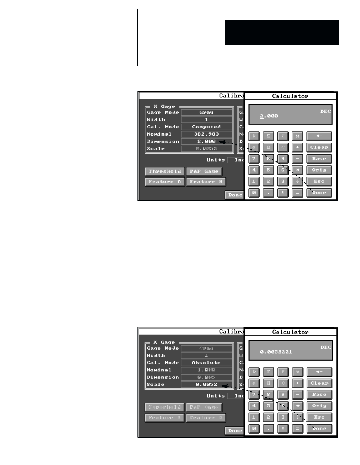
Chapter 3
Chapter
Image Acquisition Parameters
5
Figure 3.17 Performing Scale Computation to “Real World” Measurement Units
Entering Scale Value (Absolute Mode Only)
For applications in which the scale value can be calculated on the basis of
specific lens sizes and settings, and where the exact relationship between
pixels in the image field and “world units” values can be determined, you can
select the Absolute calibration mode can enter the scale values directly into
the Scale field.
Thus, if you determined that 382.983 pixels in the image field was equivalent
to 2.000 inches (to borrow from the example in Figure 3.17), you would
divide 2.000 by 382.983 to calculate the scale value (0.0052221, in this case)
and enter that value directly into the Scale field, as shown in Figure 3.18.
Figure 3.18 Example: Entering Predetermined Scale Value (Absolute Mode)
3–25
Page 65

Chapter 3
Image Acquisition Parameters
Note that the scale value that you entered (0.0052221) is rounded to four
places (0.0052) in the Scale field; however, the original value is stored in
memory exactly as you entered it.
After entering the predetermined scale values for both axes, pick the
button to exit the Calibrate panel and return to the selected Camera setup
panel. Subsequent linear measurements by gages using images from the
selected camera will be returned in Inches (in this example).
Acquisition System Settings
When you pick the button in the Acquisition Editor panel, the
Acquisition System Settings panel appears, as shown in Figure 3.19.
Figure 3.19 Selecting the Acquisition System Settings Panel
The Acquisition Systems Settings panel selects the default camera type,
the horizontal and vertical sync sources, and camera bank switching
parameters. The panel contains a scrolling list and several parameter
selection fields, which are described briefly as follows:
• Default Camera Type panel –– This scrolling list panel enables you to
select a default camera type. This camera type sets the horizontal and
vertical timing and scan modes for the entire system.
• Horizontal Reference box –– This box selects either the internal or an
external horizontal reference source.
• Vertical Reset Source box –– This box selects either the internal or an
external vertical reset source.
• Bank Switch Mode –– This field selects the bank switch mode. The
choices are “On Command” or “Automatic.”
3–26
Page 66

Chapter 3
Chapter
Image Acquisition Parameters
5
• Bank Switch Command Input –– This field selects the bank switch
command input assignment on either the Module I/O or the System I/O.
It is active only when the “On Command” bank switch mode is selected.
• Bank Switch State Output –– This field selects the bank switch
command output source (from either the Module I/O or the System I/O)
when the bank switch mode is “On Command.”
Default Camera Type
The CVIM2 system uses the default camera type as the basis for determining
the horizontal and vertical frequencies that regulate the “squareness” of the
pixels in the camera image. Thus, for example, when the 2801–YC camera is
selected as the default camera type, images from a 2801–YC camera will
contain the squarest possible pixels, while images from other cameras (such
as the 2801–YD) will not be square.
For applications using more than one camera type, the default camera type
should be selected for the camera(s) whose inspection tasks (such as rotation
finder) are the most sensitive to pixel squareness.
Horizontal Reference Source
For most applications, the CVIM2 system can supply horizontal timing or
“sync” signals for all cameras on the basis of the horizontal reference for the
default camera type. For some applications, however, an external horizontal
timing source may be required. Here are two such application situations
requiring an external horizontal reference:
• A non–standard camera is used, and it generates its own horizontal timing
signals and cannot be driven from the CVIM2 system.
• A “genlock” timing device is used to synchronize all CVIM2 systems and
cameras when multiple systems and/or cameras are used.
In either of these situations, “External, Cam.4 In” should be selected in the
H.Reference box. In addition, a cable from the external synchronizing
source must be attached to the camera #4 input on the CVIM2 front panel.
NOTE: The Allen–Bradley Company does not supply cables for connecting
external timing sources to the camera connectors on the CVIM2 front panel.
Thus, when a cable must be fabricated, use the pinout diagram shown in
Figure 3.20 (page 3–28) as the basis for wiring the cable.
3–27
Page 67

Chapter 3
Image Acquisition Parameters
Figure 3.20 Pinout Diagram: CVIM2 Front Panel Camera Connector
View: Facing a camera connector
on the CVIM2 front panel
Pin 1
Pin 2
Pin 3
Pin 4
Pin 5
Pin 6
Pin 7
Pin 8
Pin 9
Pin 10
Pin 11
Pin 12
Gnd
+12V Out
Video In (G)
Video In
Ext HD Out (G)
Ext HD Out
Ext VD Out
Gnd
NC
Gnd
+12V Out
Ext VD Out (G)
9
8
7
6
1
10
1112
5
2
3
4
Vertical Reference Source
For most applications, the CVIM2 system can supply vertical timing or
“sync” signals for all cameras. However, for some applications (except those
using frame reset cameras) an external vertical timing source, synchronous
or asynchronous, may be required. Here are three application situations using
an external vertical reference:
3–28
• A non–standard camera is used, and it generates its own vertical (and
horizontal) timing signals and cannot be driven from the CVIM2 system.
• A “genlock” timing device is used to synchronize all CVIM2 systems and
cameras when multiple systems and/or cameras are used.
• Two CVIM2 systems are used, and camera #1 on one system (the master)
supplies vertical (but not horizontal) “sync”to camera #1 on the other
system (the slave) through the camera #4 connector on each system.
Cameras #2 and #3 on the two systems can be linked in a similar manner
through the camera #5 and #6 connectors on each system.
In the first two situations, where both the vertical and the horizontal timing
signals must be synchronized externally “External, Synchronous, Cam.4
In” must be selected in the Vertical Reset Source box. In the third
situation, where only the vertical timing signals are synchronized, “External,
Asynchronous, Cams.4, 5 and 6 In” must be selected.
Page 68

Chapter 3
Chapter
Image Acquisition Parameters
5
Camera Bank Switching
The CVIM2 system can service three cameras inputs at one time: cameras
#1, #2, and #3, or cameras #4, #5, and #6. The bank switch function provides
a means of switching between the two “banks” of cameras while the system
is operating online. (By default, cameras #1, #2, and #3 are always selected
after system powerup.)
NOTE: In order to use camera inputs #4, #5, and/or #6, you must install an
external +24VDC power supply as described in Chapter 1, Hardware
Connection and Powerup Check.
Bank Switch Mode
The bank switching function can be initiated either on command, from a
signal on a discrete input, or automatically, from a trigger signal to the
unselected camera bank. You can choose the switching mode by picking the
Bank Switch Mode field in the Acquisition System Settings panel. When
you pick this field, it toggles from On Command to Automatic, or vice
versa.
On Command –– This bank switch mode requires using a discrete input to
select the appropriate camera bank. For this purpose, you must pick the Bank
Switch Command Input field to select an available input in either the
Module I/O or the System I/O discrete I/O editor panel.
When a signal level change occurs on the assigned input, the system switches
from one camera bank to the other. Thus, if cameras #1, #2, and #3 are
currently active, and the bank switch signal level is asserted, the system will
deactivate cameras #1, #2, and #3 and activate cameras #4, #5, and #6.
Subsequently, when the bank switch signal level drops, the system will
activate cameras #1, #2, and #3 and deactivate cameras #4, #5, and #6.
A delay will occur from the moment that the bank switch input level changes
until the system is ready to process triggers, as follows:
• Polling latency delay: approximately 25ms to respond to the level
change, plus
• Bank switch delay:
— Cameras across banks #1 and #4, #2 and #5, or #3 and #6 are
compatible (that is, both are free–running cameras, such as the
2801–YC or –YD, or both are frame reset cameras, such as the
2801–YE): approximately 80ms, or
— Cameras across banks #1 and #4, #2 and #5, or #3 and #6 are not
compatible (that is, one is a free–running camera, such as the
2801–YC or –YD, and the other is a frame reset camera, such as the
2801–YE): approximately 200ms.
3–29
Page 69

Chapter 3
Image Acquisition Parameters
Note that the delays are cumulative; that is, the total delay consists of the
polling latency plus one of the two bank switch delays.
Automatic –– This bank switch mode causes the CVIM2 system to switch
automatically to the inactive camera bank when it receives a trigger
corresponding to one of the unselected bank’s cameras. Thus, if cameras #1,
#2, and #3 were currently selected and a trigger arrived for camera #4, the
bank switch to cameras #4, #5, and #6 would take place automatically.
A delay will occur from the start of a trigger until the system is ready to
process the trigger, as follows:
• When the trigger queue is empty, no acquisition is in progress, a bank
switch is required to process the trigger, and either
— Cameras across banks #1 and #4, #2 and #5, or #3 and #6 are
compatible (that is, both are free–running cameras, such as the
2801–YC or –YD, or both are frame reset cameras, such as the
2801–YE): approximately 40ms, or
— Cameras across banks #1 and #4, #2 and #5, or #3 and #6 are not
compatible (that is, one is a free–running camera, such as the
2801–YC or –YD, and the other is a frame reset camera, such as the
2801–YE): approximately 160ms.
:
• When the trigger queue is not empty, it is placed in the trigger queue, and
processing is delayed further until all previous triggers are processed (all
triggers are handled sequentially).
Note that the delays are cumulative; that is, the total delay consists of the
trigger queue delay plus one of the bank switch delays.
3–30
Page 70

Chapter 3
ÇÇ
ÇÇ
ÇÇ
Chapter
Image Acquisition Parameters
5
Bank Switch Command Input
The Bank Switch Command Input field is active only when the On
Command bank switch mode is selected. This field accesses a discrete I/O
edit panel, where you can assign the Bank Switch command to one of the
Module I/O or System I/O inputs, and thereby control bank switching from
your process equipment.
When you pick the Bank Switch Command Input field in the Acquisition
System Settings panel, the Module I/O panel appears, as shown in
Figure 3.21.
Figure 3.21 Example: Assigning Bank Switch to Module I/O Input 0
(Note that the Module I/O panel always appears first by default. If you want
to assign the bank switch function to a System I/O input, you can pick the
button to access the I/O Device panel, from which you can then
select the System I/O panel.)
As the example in Figure 3.21 illustrates, when you pick the “In 0” field in
the Module I/O panel, “Bank Switch” appears in the field, indicating that it
is now assigned as Module I/O input 0. (Note that you can remove Bank
Switch from input 0 by picking the same field again.)
After assigning the bank switch function to the appropriate input, pick the
button to exit back to the Acquisition System Settings panel.
3–31
Page 71

Chapter 3
Image Acquisition Parameters
Bank Switch State Output
The Bank Switch State Output field accesses a discrete I/O edit panel,
where you can assign the Bank State status signal to one of the Module I/O
or System I/O outputs, and thereby enable the CVIM2 system to signal your
process equipment when a bank switch has occurred.
NOTE: The Bank State signal is always inactive when cameras #1, #2, and
#3 are active, and is always active when cameras #4, #5, and #6 are selected.
When you pick the Bank Switch State Output field in the Acquisition
System Settings panel, the Module I/O panel appears, as shown in
Figure 3.22.
Figure 3.22 Example: Assigning Bank State to Module I/O Output 2
3–32
(Note that the Module I/O panel always appears first by default. If you want
to assign the Bank State signal to a System I/O output, you can pick the
button to access the I/O Device panel, from which you can then
select the System I/O panel.)
As the example in Figure 3.22 illustrates, when you pick the “Out 2” field in
the Module I/O panel, “Bank State” appears in the field, indicating that it is
now assigned as Module I/O output 2. (Note that you can remove Bank
State from output 2 by picking the same field again.)
Page 72
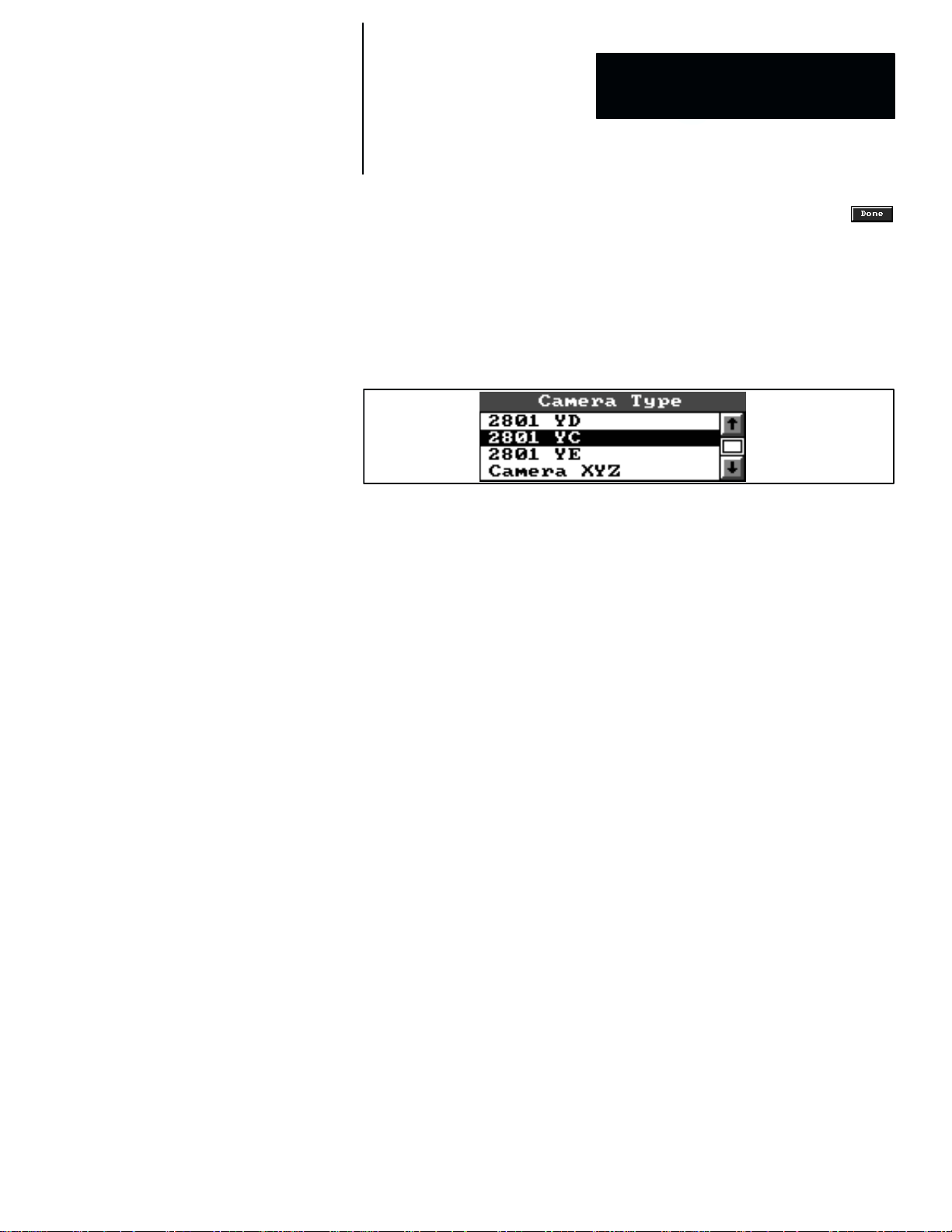
Chapter 3
Chapter
Image Acquisition Parameters
5
After assigning the bank state status to the appropriate output, pick the
button to exit back to the Acquisition System Settings panel.
Camera Type: Selection and Editing
The Camera Type scrolling list, as shown in Figure 3.23, appears in two
places: the Acquisition Editor panel, and all of the Camera panels.
Figure 3.23 Example: Camera Type Scrolling List Panel
This list shows all of the “standard” cameras that the Allen–Bradley
Company supports, along with any number of non–standard cameras (such
as “Camera XYZ” in the example) that a user has configured for use with
the CVIM2 system.
The highlighted camera name in the scrolling list is the currently selected
camera type (2801 YC in the example). To select another name, just pick the
name. When you do, the new name is highlighted and the previous name is
unhighlighted.
In the Acquisition Editor panel, you can edit some of the selected camera’s
timing parameters, and you can copy a listed camera type to create a new
non–standard camera type under a different name.
In a Camera panel, the selected camera type should correspond to the type
that will be connected to the camera port whose number is shown in the
Camera panel title bar (such as “Camera 1”). In addition, you can edit
some of the selected camera’s timing parameters.
Camera Type Edit Panel
The Camera Type edit panel contains several parameter selection boxes and
fields pertaining to the camera timing and scan modes for each camera type.
For the standard Allen–Bradley cameras (2801–YC, –YD, YE, and YF),
most of these parameters are inaccessible –– they cannot be changed. For
non–standard camera types, however, most of the parameters are accessible
and can be changed to whatever values are appropriate for a particular
non–standard camera.
3–33
Page 73

Chapter 3
Image Acquisition Parameters
Editing Standard Allen–Bradley Cameras
When you highlight one of the standard camera types in the Camera Type
scrolling list panel and then pick the
button below the panel, a
Camera Type edit panel appears. Figure 3.24 shows the edit panel for the
2801–YC “standard” camera. The parameters shown in shaded type are the
ones that cannot be changed for standard Allen–Bradley cameras. For these
cameras, only a few of the horizontal and vertical timing parameters can be
changed.
Figure 3.24 Example: Selecting Camera T ype Edit Panel
3–34
Although these parameters can be adjusted, the default values for the current
standard Allen–Bradley cameras are normally appropriate for most
applications.
The effect of adjusting the Horizontal Timing parameters is described
briefly, as follows:
Acq. Pixels (Pixels) –– This parameter indicates the number of pixels that
are acquired across the image horizontally. Normally, the default setting of
512 is appropriate; however, the Acq.Phase (Pixels) value can be set within
the following range:
64 x Value x 640 * 2(Acq. Phase)
Figure 3.25 (page 3–35) shows the effects of changing the value of the Acq.
Pixels (Pixels) parameter to 640 (the maximum) and 64 (the minimum). As
the examples in Figure 3.25 show, the effect of increasing the value is to
acquire the image, up to its full width (640 pixels), while the effect of
decreasing the value is to truncate the image equally on both sides of the
image. In this case, only the center 64 pixels of the image is acquired.
Page 74

Chapter 3
Chapter
Image Acquisition Parameters
5
Figure 3.25 Example: Effect of Different Acq.Pixels Settings on Displayed Image
Acq. Phase =
0 (all)
Acq. Pixels =
512
Acq. Pixels =
64
Acq. Pixels =
640
Acq. Phase (Pixels) –– The acquired pixels are normally centered within the
camera’s field of view (centered on pixel 320 out of 640). By changing the
value of the Acq. Phase (Pixels) parameter, you can shift the center of the
acquired region left or right. Normally, the default setting of 0 is appropriate;
3–35
Page 75

Chapter 3
Image Acquisition Parameters
however, the Acq.Phase (Pixels) value can be set within the following
range:
*(640 – Acq. Pixels) B 2 x Value x )(640 – Acq. Pixels) B 2
NOTE: Changing the Acq. Pixels and Acq. Phase values does not affect
the image acquisition time.
The example in Figure 3.26 shows the effect of changing the value of the
Acq. Phase (Pixels) parameter to 64 (with the Acq. Pixels (Pixels)
parameter set to 512, in this case). Note that this image appears shifted to the
left, compared to the “512” image shown in Figure 3.25 (page 3–35). In fact,
the leftmost 64 pixels of the image are truncated in this case.
Figure 3.26 Example: Effect of Maximum Acq. Phase Setting on Displayed Image
Acq. Pixels = 512Acq. Phase = 64
In Figure 3.27 (A) on page 3–37, the dotted lines show that the center of the
512 acquired pixels is centered in the full 640–pixel image when Acq.
Phase (Pixels) is set is 0. In Figure 3.27 (B), the dotted lines show that the
center of the 512 acquired pixels has moved 64 pixels to the right when the
Acq. Phase (Pixels) is set is 64 (this is the example shown in Figure 3.26).
3–36
Note that the reverse would be true if the Acq. Phase (Pixels) were set to
–64. In that case, the displayed image would appear shifted to the right.
In another example, shown in Figure 3.27 (C), if you wanted only the
rightmost 200 pixels in the image to be acquired, you could set Acq. Phase
(Pixels) to 220 and Acq. Pixels (Pixels) to 200.
Page 76

Chapter 3
Chapter
Image Acquisition Parameters
5
Figure 3.27 Example: Effect of Acq. Phase Settings on Acquired Pixels
Full 640–pixel
image field
A
512 acquired
pixels
Acq. Phase = 0
Full 640–pixel
image field
B
512 acquired
pixels
Acq. Phase = 0 Acq. Phase = 64
Full 640–pixel
image field
C
200
acquired
pixels
Acq. Phase = 220
3–37
Page 77

Chapter 3
Image Acquisition Parameters
The effect of adjusting the Vertical Timing parameters is described as
follows:
Acq.Start (1/2 Lines) –– This parameter indicates the point at which the
image acquisition begins for the purpose of image processing and display.
Normally, the default setting of 40 is appropriate; however, the Acq.Start
(1/2 Lines) value can be set within the following range:
40 x Value x 40 + (480 * Acq. Lines)
Acq.Lines (1/2 Lines) –– This parameter indicates the number of half–lines
of the image field that are acquired, beginning at the starting point set by the
Acq.Start (1/2 Lines) parameter. Normally the default value of 480 is
appropriate; however, the Acq.Lines (1/2 Lines) value can be set within the
following range:
64 x Value x 520 * Acq. Start
Figure 3.28 (page 3–39) illustrates three image displays in which the
Acq.Lines (1/2 Lines) values are set to 480 (default), 240 and 64.
As the examples in Figure 3.28 show, the effect of decreasing the value of
the Acq.Lines (1/2 Lines) parameter is to reduce the number of half–lines
acquired, and the result is to decrease the image height.
Changing both of these parameters might be useful in a situation in which a
narrow, horizontally oriented inspected object lies in a narrow band at the
center (or lower) part of the image. In this case, you could set the Acq.Start
(1/2 Lines) parameter to, for example, 220, and set the Acq.Lines (1/2
Lines) parameter to 64. The result would be a vertically narrow image with
just enough room to contain the inspected object.
Figure 3.29 (page 3–40) illustrates the result, using a pen as the inspected
object. In this example, the pen was located in a lower part of the unmodified
full image, whereas the vertically truncated image containing the pen appears
“justified” at the top of the image display.
In all cases the sum of the Acq.Start (1/2 Lines) setting and the Acq.Lines
(1/2 Lines) setting cannot exceed 523. Any combination of the two
parameters is acceptable whose sum does not exceed 523.
3–38
Page 78

Chapter 3
Chapter
Image Acquisition Parameters
5
Figure 3.28 Example: Effect of Various Acq. Lines (1/2 Lines) Settings on Image
Acq. Start (1/2 Lines) = 40 (all)
Acq. Lines (1/2 Lines) = 480
(default)
Acq. Lines (1/2 Lines) = 240
Acq. Lines (1/2 Lines) = 64
3–39
Page 79

Chapter 3
Image Acquisition Parameters
Figure 3.29 Example: Effects of Changing Horizontal Image Acquisition Parameters
Acq. Start (1/2 Lines) = 220
Acq. Lines (1/2 Lines) = 64
Editing Non–Standard Cameras
A non–standard camera is any camera other than the Catalog No. 2801–YC,
–YD, –YE, or –YF cameras that the Allen–Bradley Company offers. In order
to accommodate a non–standard camera, you must “create” a new camera
type under an appropriate name, then access that camera’s edit panel and
enter the timing and scan mode parameters that are appropriate for that
camera.
This is done by highlighting one of the standard camera types, then picking
the
button to “copy” that camera type under a different name, one that
is appropriate for the camera type.
When you highlight a non–standard camera type in the Camera Type
scrolling list panel, and then pick the
button below the panel, a
Camera Type edit panel appears. Figure 3.30 (page 3–41) illustrates this
with the example “Camera XYZ” non–standard camera. Note that most of
the parameter selections in this edit panel are shown in light type, which
indicates that they can be changed.
3–40
Page 80

Chapter 3
Chapter
Image Acquisition Parameters
Figure 3.30 Setup Camera T ype Panel: Camera XYZ
5
Most of the data for these parameter selections can be obtained from the user
and/or service manuals that are supplied with the non–standard camera. Here
is a brief description of each parameter selection field and box in the
Camera Type edit panel.
• H.Scan Mode –– This box selects either a normal speed or a double
speed scan mode. The basic difference is that a normal speed camera
acquires 240 vertical lines of data in 17ms, while a double speed camera
acquires 480 vertical lines of data (a “full” frame) in 17ms. The double
speed camera also has frame reset capability.
• V.Scan Mode –– This box selects interlaced operation using one or two
fields, or non–interlaced operation, according to the camera type in use.
For the 2801–YC and –YD cameras, Interlaced, 2 Fields is selected,
while for the 2801–YE frame reset camera, Interlaced, 1 Field is
selected. In each case, the other selections are inactive (shaded type), and
cannot be selected. For non–standard cameras, the V.Scan mode
selection can be determined from the camera manufacturer’s
specifications.
• Reset/Delay Mode –– This box selects the free running mode or one of
the reset/delay modes, according to the camera type in use. For the
2801–YC and –YD cameras, Free Running is selected, while for the
2801–YE frame reset camera, Reset, Double Pulse VD is selected. In
each case, the other selections are inactive (shaded type), and cannot be
selected. For non–standard cameras, the appropriate Reset/Delay mode
selection can be determined from the camera manufacturer’s
specifications.
3–41
Page 81

Chapter 3
Image Acquisition Parameters
• Period (ms) –– This is amount of time required to scan one horizontal
line. It is equal to the reciprocal of the horizontal frequency. (For the
2801–YC camera, the horizontal frequency is 15.734KHz; thus, the
period is 1 B 15.734KHz = 63.557ms.)
• HD Length –– This is the duration, stated in microseconds, of the “active
low” HD (horizontal drive) pulse provided to the camera from the CVIM2
system.
• Restore Start (ms) –– This is starting point of the DC restore pulse, which
the CVIM2 system uses during each horizontal line to “sample” the
analog composite video signal at a time when the camera sees “black.”
(For the 2801–YC camera, the center of this pulse is located halfway
between 6.3ms and 10.8ms after the start of the horizontal drive pulse;
thus, the start of the restore start pulse is 8.2ms after the start of the
horizontal drive pulse.)
• Restore Length (ms) –– This is the duration of the DC restore pulse. (For
the 2801–YC camera, it is 1ms.)
• Acq. Center (ms) –– This is the center of the image sensing area (the
acquired picture), in microseconds, after the start of the horizontal drive
pulse. (For the 2801–YC camera, it is 37.20ms after the start of the HD
pulse.)
• Acq.Pixels (Pixels) –– Refer to the Editing Standard Allen–Bradley
Cameras section for details.
• Acq.Phase (Pixels) –– Refer to the Editing Standard Allen–Bradley
Cameras section for details.
• Total (Pixels) –– This value represents the number of times that the
CVIM2 system “samples” each horizontal line of the analog composite
video signal from the camera in the process of digitizing the video signal.
NOTE: The frequency range limit of the CVIM2 system is 10MHz to
20MHz. Since the frequency is a function of the camera’s period and the
Total (Pixels) selection, any combination of these values must lie within
that range. The frequency is the reciprocal of the camera’s period divided
by the total pixels; or stated another way, the total pixels divided by the
period. For example, the period of the 2801–YC camera is 63.557ms, and
the total pixels is 794. Thus, the frequency is 794 B 63.557ms, or
12.5MHz, which is well within the CVIM2 system’s frequency range
limits.
• Transfer (1/2 Lines) –– This value applies only to free–running,
interlaced CCD cameras. “Transfer” refers to the process by which image
data is transferred from the image sensor to the shift register for the
current image field. During this time, the CVIM2 will not fire a strobe.
The Transfer value indicates the time, stated in 1/2 lines, around which a
strobe will not be fired. For the 2801–YC camera, the Transfer value is
the 16 half lines, and the transfer time is two half lines before to two half
lines after this point. Thus, the CVIM2 system will not fire a strobe
during that interval.
3–42
Page 82

Chapter 3
Chapter
Image Acquisition Parameters
5
NOTE: For MOS–type cameras, which do not use shift registers, the
Transfer value can be set to –1 to disable the strobe–inhibiting period.
These cameras have no restrictions as to when the strobe can be fired.
• Int. Start (1/2 Lines) –– This value applies only to frame reset cameras.
Int. Start is the time, stated in 1/2 lines, after the assertion of the first
vertical drive (VD) pulse. This is the point at which the camera starts
image integration.
• Int. End (1/2 Lines) –– This value applies only to frame reset cameras.
Int. End, stated in 1/2 lines, indicates the point at which a frame reset
camera stops image integration.
For cameras using the Reset, Delay on VD ↓ selection, it is the time
after the active–low vertical drive (VD) pulse goes “up” (high) that the
camera stops image integration. For cameras using the Reset Double
Pulse VD selection, it is the time after the assertion of the second VD
pulse. This is the point at which the camera stops image integration.
For cameras using the Reset, Delay on VD ↑ and Reset, No Delay
selections, Int. End has no meaning.
• VD Length (1/2 Lines) –– This value is the duration, stated in 1/2 lines,
of the “active low” VD (vertical drive) pulse from the CVIM2 system.
(For frame reset cameras using the Reset, Delay on VD ↓ selection, the
length increase by the amount of the selected shutter speed.)
• Acq. Start (1/2 Lines) –– Refer to the Editing Standard Allen–Bradley
Cameras section for details.
• Acq. Lines (1/2 Lines) –– Refer to the Editing Standard Allen–Bradley
Cameras section for details.
• Total (1/2 Lines) –– This value is the total number of half lines that the
camera system uses in one cycle. For the Allen–Bradley standard
cameras, Total is always 525.
3–43
Page 83

Chapter 3
Image Acquisition Parameters
Trigger Setup Panel
When you highlight a toolset trigger name in the Toolset Trigger scrolling
list and then pick the
button below the list, the corresponding
Toolset Trigger setup panel appears, as shown in Figure 3.31.
Figure 3.31 Example: Selecting Trigger Setup Panel
3–44
NOTE: Initially, the term “None” appears in this list. A toolset trigger
name will appear in the Toolset Trigger list only after an inspection name
has been defined for a toolset in the Configuration Editor panel, as described
in Chapter 4, Inspection Configuration, on page 4–9.
The selections in the Toolset Trigger setup panel determine the camera port,
the trigger source, and four of the discrete I/O settings for online inspection
operations. These selections apply only to the particular toolset named in the
title bar of the Toolset Trigger panel. Thus, in the example in Figure 3.31,
the toolset is named “Toolset 12.”
Here is a brief description of the selections in the Toolset Trigger panel:
• Cameras –– This selects the camera(s) to be used for the toolset.
• Trigger –– This selects the trigger source for the toolset.
• Rate per Minute –– When “Auto” is selected as the (internal) trigger
source, this selects the number of trigger signals per minute.
Page 84

Chapter 3
Chapter
Image Acquisition Parameters
5
• Source I/O –– When “I/O” is selected as the (external) trigger source,
this selects the discrete input in the Discrete I/O Edit panel.
• Strobe I/O –– When a strobe light is to be used, this selects the discrete
output for the strobe trigger.
• Ack I/O –– For applications requiring the trigger ACK signal, this selects
a discrete output for the signal.
• Nak I/O –– For applications requiring the trigger NAK signal, this selects
a discrete output for the signal.
NOTE 1: The trigger source and signal assignments can be applied only to
cameras 1, 2, and/or 3, or cameras 4, 5, and/or 6. This is shown in
Figure 3.32. Camera #1 is selected initially by default.
Figure 3.32 Example: Inactive Camera Selections in T oolset Trigger Panel
NOTE 2: When camera 4, 5, or 6 is used, an external +24VDC power
supply must be used, as described in Chapter 1, Hardware Connection and
Powerup Check, of this manual, and the Allen–Bradley Pyramid Integrator
Installation Manual, Publication 5000–6.2.10, which is supplied with the
Pyramid Integrator chassis.
The trigger selection field in the Toolset Trigger panel, shown in
Figure 3.33, offers two choices of trigger operation based on an internal
source (Auto) or an external source (I/O). Figure 3.33 shows that Auto is
currently selected. To “toggle” to I/O, pick the Trigger field. To toggle back
to Auto, pick the field again.
Figure 3.33 Trigger Selection Field in Trigger Setup Panel
3–45
Page 85

Chapter 3
Image Acquisition Parameters
The Auto selection uses the CVIM2 system’s internal trigger source,
whereas the I/O selection uses one of the discrete inputs for an external
trigger source.
The internal trigger’s default trigger signal rate is 600 triggers per minute. To
change the rate, pick the Rate per Minute field. When you do, the
“calculator pad” appears, as shown in Figure 3.34. Enter any value within a
range of 30 to 3600 by picking the appropriate digits for that value, then
picking the
Figure 3.34 Using Calculator Pad to Change Internal Trigger Rate
button (in the calculator pad).
3–46
To select an external trigger source, you must assign the current inspection to
one of the discrete trigger inputs. Pick the Trigger field to toggle it to “I/O,”
then pick the Source I/O field. When you do, the Discrete I/O Set Signal
panel appears, as shown in the example in Figure 3.35 (page 3–47).
As an example, if you want to assign inspection #1 to the “In 0” input, simply
pick the “In 0” input line, and the trigger name will appear on the “In 0”
line, as shown by “Toolset 1.Trigger” in Figure 3.35.
The strobe signal and the trigger NAK and ACK signals can be assigned to
discrete outputs in a similar manner. Refer to Chapter 9, Discrete I/O
Assignments, page 9–9, for more information about these signals.
Page 86

Chapter 3
Chapter
Image Acquisition Parameters
5
Figure 3.35 Example: Assigning Inspection to Discrete Input
3–47
Page 87

Chapter
4
Inspection Configuration
The CVIM2 system can be configured to perform a single inspection or
multiple related inspections. Each inspection involves the selection of
parameters that define the inspection sequence, the I/O interface, camera
usage, and communication messages. These parameters are stored in various
files that are referred to collectively as a configuration. A configuration file
is used to link all of the parameter files required for the single inspection or
multiple related inspections. Figure 4.1 illustrates the relationship between a
configuration file and the tool, discrete I/O, acquisition, and communication
files.
Figure 4.1 Configuration File Organization
Environment
On–line memory
etc.
Config. filename
Configuration File #1
Toolset 1
Inspection name
Archive name
Inspection settings
Display settings
Toolset 6
Inspection name
Archive name
Inspection settings
Display settings
Acquisition File Name
Tools File #1
Configuration File #2 Configuration File #3
Tool 1 parameters
Tool 2 parameters
. . .
Tool N parameters
Tools File #6
Tool 1 parameters
Tool 2 parameters
. . .
Tool N parameters
Acquisition File
System settings
Line settings
Camera settings
Trigger settings
Discrete I/O File Name
Message File Name
Discrete I/O File
Module I/O assignments
System I/O assignments
Remote I/O assignments
LED assignments
Message File
Message 1 settings
Message 2 settings
. . .
Message N settings
4–1
Page 88

Chapter 4
Inspection Configuration
Typically, a configuration file is given a name that indicates its role in the
overall inspection application. Similarly, each toolset is named for its role.
(For example, the configuration file, toolset, and tool archive file might be
named “32oz Bottle,” “FrontLabel,” and “32ozFrontLbl,” respectively.)
The user places the CVIM2 system online by selecting one configuration file
by its name, then selecting the online mode.
This chapter discusses the process of inspection configuration, which
involves naming a configuration file and selecting a camera source, trigger
source, and one or more inspection tools for at least one inspection.
Configuration Process
The first step in the configuration process is to create a configuration file. As
shown in Figure 4.1, this file will contain inspection and display settings, and
the names of other files that contain the inspection tools for each toolset, the
discrete I/O settings, the acquisition settings, and the communication
message definitions.
The configuration process begins when you pick Environment in the main
menu bar, then pick Config in the Environment menu. When you do, the
Config Files panel appears initially as shown in Figure 4.2.
Figure 4.2 Initial Appearance of Config Files Panel
Main menu
bar
4–2
Page 89

Chapter 4
Chapter
Inspection Configuration
5
Note that the Config Files panel contains several data entry fields and
“buttons.” Here is a brief description of their functions:
• Config –– Pick this field to select the current list of Config file names
and/or enter new Config file names.
• *Discrete I/O –– Pick this field to select the current list of Discrete I/O
file names and/or enter new Discrete I/O file names.
• *Message –– Pick this field to select the current list of Message file
names and/or enter new Message file names.
• *Acq. Config –– Pick this field to select the current list of Acq. Config
file names and/or enter new Acq. Config file names.
When you pick one of the above fields, the name (such as Config in
Figure 4.2) appears above the “scrolling” list, and the corresponding file
names (if any) appear in that list. In Figure 4.2, no Config file names
have yet been selected; thus, the scrolling list is empty.
• Add –– Use the button to add new entries in the Config Files panel.
• Save –– Use the button to save the entries in the Config Files
panel without exiting to the main menu bar.
• Done –– Use the button to save the entries in the Config Files
panel and exit to the main menu bar.
• Cancel –– Use the button to exit to the main menu bar without
saving any new entries that you set up while in the Config Files panel.
*The names of the discrete I/O, message, and acquisition files will all be
stored in the configuration file.
Two file types must be named in order to complete a configuration file: A
Config file type, and an Acq. Config file type.
When you pick the Config field, then pick the
panel appears as shown in Figure 4.3 (page 4–4).
The message at the top of the keyboard panel instructs you to: “Enter a file
name . . .” That name will become the new Config file name.
When you enter a new Config file name in the keyboard (for example,
FrontLabel) and then pick the
the scrolling list, as shown in Figure 4.4 (page 4–4). (Note that the new
Config file name also appears in the Config field since it is currently
highlighted in the list.)
key, the FrontLabel name appears in
button, the keyboard
4–3
Page 90

Chapter 4
Inspection Configuration
Figure 4.3 Selecting New “Config” File Name
Figure 4.4 Example: Configuration Files Panel With New “Config” Name Entered
4–4
Page 91

Chapter 4
Chapter
Inspection Configuration
5
NOTE: If you attempt to exit the Config Files panel at this time by picking
the
This message indicates that the specified configuration file,
“EE:FrontLabel,” must contain the name of an “Acq. Config” file. You
must enter an Acq. Config file name before exiting the Config Files panel.
A similar message will appear if you attempt to exit without entering a
“Config” file name.
button, the following message will appear:
If this message appears, pick the
panel and enter an Acq. Config file name.
When you pick Acq. Config field, then pick the
panel appears as shown in Figure 4.5.
Figure 4.5 Selecting New “Acq. Config” File Name
button to return to the Config Files
button, the keyboard
The message at the top of the keyboard panel instructs you to: “Enter a file
name . . .” That name will become the name of your new Acq. Config file.
Note that the name “EE:FrontLabel.acq” appears in the keyboard name
field. This name is derived from the Config file name currently appearing in
4–5
Page 92

Chapter 4
Inspection Configuration
the Config field. You can use this name, if it is appropriate for your
application, or you can enter a different name.
When the appropriate Acq. Config file name is in the keyboard, and you
pick the
key, that file name appears in the scrolling list, as shown for
the Config file name in Figure 4.4 (page 4–4). (Note that the new name also
appears in the Acq. Config field since it is currently highlighted in the list.)
Configuration Editor Panel
If you exit the Config Files panel at this time by picking the
button,
the following message will appear briefly . . .
Configuration save complete
. . . after which the system will exit to the main menu bar.
At this point, a minimum “configuration” has been named, and you can now
pick the Configuration Editor panel from Editor in the main menu bar, as
described in the next section, Configuration Editor Panel.
To enter the Discrete I/O and/or Message file names before exiting the
Config Files panel, use the procedure described above to enter those file
names.
The main purpose of the Configuration Editor panel is to designate the
inspection parameters and inspection tool sets for each toolset in a
configuration file.
NOTE: Before you can select the Configuration Editor panel, you must
first create or select a configuration file with a valid Config file name, as
described in the preceding section, Configuration Process; otherwise, the
following message will appear when you attempt to select the Configuration
Editor panel:
4–6
If this message appears, you must pick the button, then select the Config
Files panel (see Figure 4.2, page 4–2) to set up (and select) at least one
configuration before proceeding.
Page 93

Chapter 4
Chapter
Inspection Configuration
5
Assuming that at least one configuration has been set up and selected, when
you then pick Editor in the main menu bar, and then pick Configuration in
the Editor menu, the Configuration Editor panel appears, as shown in
Figure 4.6.
Figure 4.6 Example: Configuration Editor Panel With Six Inspections
Note that the configuration editor panel contains several data entry fields and
“buttons.” Here is a brief description of their functions:
• Num –– This field contains the number of a “toolset,” such as 1, 2, or 3.
(This number is fixed –– you cannot change it.)
• Inspection Name –– The inspection name is used to identify a toolset for
I/O, communication, and display purposes. Use this field to select a name
(up to 15 characters) for a toolset. (The default inspection names for the
six toolsets are Toolset 1, Toolset 2, and so on.)
• Archive Name –– The “archive name” identifies the device and file in
which the inspection tools are stored. Use this field to enter a name (up to
16 characters) of either a new file of inspection tools or an existing file of
inspection tools. (By default, the archive names for the six toolsets take
this form: EE:config filename.ts1, EE:config filename.ts2, and so on).
• Add –– Use the button to add new toolsets in the Configuration
Editor panel. (Alternatively, you can pick the inspection name field to
perform this function.)
4–7
Page 94

Chapter 4
Inspection Configuration
• Cut –– Use the button to delete the toolset that has the cursor arrow
(→) alongside the toolset number. Thus, if the cursor arrow is located at
number 2, the toolset at that location will be deleted.
• Inspection –– Use the button to access a toolset’s Inspection
parameter selection panel.
• Display –– Use the button to access a toolset’s Display
parameters selection panel.
• Setup –– Use the button to access the image/tool display panel
and the tool configuration setup panel.
• Done –– Use the button to save the entries in the Configuration
Editor panel and exit to the main menu bar.
• Cancel –– Use the button to exit to the main menu bar without
saving any new inspection names or any parameters that you set while in
the Inspection and/or Display panels. (However, tools that you
configured and saved while in the Setup panel, and parameters that you
entered and saved while in the Acquisition Editor panel, will remain as
you saved them.)
• Save –– Use the button to save additions and/or changes to the
contents of the Configuration Editor panel without exiting the panel.
• Acquisition –– Use the button to access the Acquisition
Editor panel (see Chapter 3, Image Acquisition Parameters).
Inspection Names and Archive Names
As noted earlier, a configuration file (such as FrontLabel) can contain up to
six toolsets. Each toolset specifies camera and trigger sources and a set of
inspection tools. The “inspection name” and the “archive name” of each
toolset appear in the Configuration Editor panel.
An inspection name (such as Toolset 1) identifies one toolset for I/O,
communication, and display purposes. In a given application, the inspection
name of a given toolset is normally the same for all configurations.
An archive name (such as EE:FrontLabel.ts1) identifies a file that consists
of one or more inspection tools (gages, windows, and so on) that are
configured together for a specific inspection task. In a given application, the
archive name of a given toolset is normally different for each configuration.
Figure 4.7 (page 4–9) illustrates the Configuration Editor with three
toolsets defined.
Each of the three toolsets that make up the “FrontLabel” configuration has
an Inspection Name and an Archive Name associated with it.
4–8
Page 95

Chapter 4
Chapter
Inspection Configuration
5
Figure 4.7 Example: Configuration Editor Panel With Three inspections Defined
Basic Configuration Procedure
The basic configuration procedure described in this section begins with the
Configuration Editor panel as shown in Figure 4.6 (page 4–7) and steps
through the major system configuration tasks, which are these:
• Selecting an inspection name.
• Configuring acquisition parameters.
• Selecting inspection parameters.
• Selecting image/results display parameters.
• Setting up inspection tools.
• Selecting discrete I/O functions.
Selecting Inspection Name
Note that the Configuration Editor panel in Figure 4.6 contains no
inspection names. Consequently, the
buttons are inactive (shaded). The , , , and
buttons are all active (white).
The first task, therefore, is to add a toolset by picking the
picking an Inspection Name field, as shown in Figure 4.8 (page 4–10).
Using either method, the keyboard appears, as shown in Figure 4.8.
, , , and
button, or by
4–9
Page 96

Chapter 4
Inspection Configuration
Figure 4.8 Selecting an Inspection Name
The default inspection name, Toolset 1, appears in the keyboard name bar
initially. You can either accept the default inspection name (if it has not
already been used), or you can select a new name.
If you select the default inspection name, the Configuration Editor panel
will appear as shown in Figure 4.9.
Figure 4.9 Configuration Editor Panel With First Inspection Named
4–10
Page 97

Chapter 4
Chapter
Inspection Configuration
5
Note that the default inspection name (Toolset 1) now appears in the first
field under Inspection Name, and the default archive name
(EE:FrontLabel.ts1) appears under Archive Name.
Configuring Acquisition Parameters
NOTE: The default acquisition parameters are sufficient for obtaining
images without a strobe light or external trigger. You can skip directly to the
Setting Up Inspection Tools section on page 4–20 if you are just getting
started.
At this point you should pick the button and configure the image
acquisition parameters, which involves the selection of toolset trigger,
camera, and acquisition system parameters. For details about these
parameters, refer to Chapter 3, Image Acquisition Parameters.
Selecting Inspection Parameters
The Inspection setup panel is accessible from the Configuration Editor
panel, as shown in Figure 4.10, by picking the button.
Figure 4.10 Selecting Inspection Panel
4–11
Page 98

Chapter 4
Inspection Configuration
Note that the Inspection panel, unlike the Acquisition Editor panel, shows
inspection settings for a single toolset.
The parameters listed in the Inspection panel, and the methods of setting
them, are described as follows:
• Overlap Acq/Insp –– This parameter can be set to a range of 0 to 20. If it
is set to 0, the system cannot acquire a new image until it finishes
processing the last image. If it is set to a value greater than 0, the system
can acquire new images while it is still processing a previous image.
• Minimum Time –– This parameter sets the amount of time, in
milliseconds, that tool inspection results will be delayed following the
start of each inspection cycle. This value can be set as required to
synchronize the CVIM2 system output with the user’s process equipment.
The valid range is 0 to 5000 milliseconds.
• Samples –– This parameter sets the size of a block of “sample”
inspections that the CVIM2 system will use to calculate statistics for a
particular tool.
• Range Failures –– This function can be set to Include or Exclude. If
Range Failures is set to Include, the CVIM2 system will include
“failed” tool results in statistical calculations. (“Failed” means tool results
that lie beyond any of the range limits.) If Range Failures is set to
Exclude, the system will exclude failed tool results from calculations.
Overlap Acq/Insp
This selection enables the CVIM2 system to overlap the image acquisition
and inspection processing functions, and thereby acquire and store a “burst”
of images before all images have been processed. The setting of the Overlap
Acq/Insp parameter determines the maximum number of images that the
system is allowed to store while image processing is still in progress.
If this parameter is set to 0 when a trigger occurs, the system acquires an
image, then processes it, then acquires the next image, processes it, and so
on, in serial fashion. Thus, the total time for the entire cycle is the image
acquisition time plus the image processing time, as shown below:
Acquisition Inspection processing
Trigger
Acq.
Next possible
trigger
If this parameter is set to 1 (or more) when a trigger occurs, the system will
acquire the first image and begin processing it. The system can then begin
acquiring another image if a trigger signal arrives before the system finishes
processing the first acquired image. The setting of the Overlap Acq/Insp
parameter determines the number of images that may be overlapped before a
trigger NAK is issued.
4–12
Page 99

Chapter 4
Chapter
Inspection Configuration
5
In the following example, the Overlap Acq/Insp parameter is set to 3, which
means that the CVIM2 system is configured to store up to three images
before the image processing for the previous image is completed. In this case,
if another trigger occurs before that completion, the system will issue a
trigger NAK.
Overlap example with Overlap Acq/Insp parameter set to 3
Acq. 1
Trigger 1
Acq. 2 Acq. 4Acq. 3
Trigger 2 Trigger 3 Trigger 4 Trigger 5 Trigger 6 = NAK
Insp. Proc. 1
In the example, a series of six triggers occurs. The interval between these
triggers is as short as possible consistent with completing each image
acquisition.
The sequence of events is as follows:
Acq. 5
Insp. Proc. 2 Insp. Proc. 3
• Trigger 1 occurs and starts the image 1 acquisition.
• When image 1 has been acquired, processing begins on image 1. This
releases the storage resource used by image 1 and makes it available for
another image acquisition (image 2). At the same time, trigger 2 occurs to
start the image 2 acquisition.
• Before image 1 has been processed, two more images will have been
acquired and stored (images 2 and 3), and another image acquisition will
have begun (image 4).
• Midway through the image 4 acquisition, processing for image 1 ends and
processing for image 2 begins. This releases the storage resource used by
image 2 and makes it available for another image acquisition (image 5).
• Before image 2 processing is complete, three images will have been
acquired and stored (images 3, 4, and 5). This is the maximum that is
allowed by the Overlap Acq/Insp parameter (3) in this example.
• Also before the second image processing is complete, trigger 6 occurs.
Since three images are already stored, and the system cannot store a
fourth image (in this example), it issues a Trigger NAK signal in response
to trigger 6.
NOTE: The maximum setting for the Overlap Acq/Insp parameter is 20;
however, because of the limitations of the image memory buffers, the
maximum setting in a particular application depends on whether the system
can be placed online. If the system will not go online with the current setting,
that setting may have to be reduced, or other adjustments may need to be
made, to enable the system to go online.
4–13
Page 100

Chapter 4
Inspection Configuration
Minimum Time
The Minimum Time field enables you to specify a fixed minimum time
interval (in milliseconds) between the start of an inspection and the
availability of inspection results. The effect is to delay the inspection results
in order to ensure that they are always available to a host system on a timely
basis. The valid range for the time interval is 0 to 5000 milliseconds.
The relation of the inspection start to the inspection results without a fixed
minimum time interval (that is, a setting of 0) is shown below:
Example of timing without
fixed minimum time interval:
Trigger
Inspection
Inspection
results
Interval varies
with inspection
The relation of the inspection start to the inspection results with a fixed
minimum time interval (that is, a setting of more than 0) is shown below:
Example of timing with
Trigger
Inspection
Inspection
results
fixed minimum time interval:
Fixed minimum
delay interval
Samples
The Samples field enables you to select an appropriate “sample” size,
ranging from 0 to 65535, for each toolset in a configuration. This value
determines the number of “sample” inspection results that the CVIM2 system
must acquire in order to calculate statistical data for a particular tool. (Note
that this function applies only to a tool for which statistics collection can be
selected, such as a window tool, and for which the Statistics box has been
checked in the Options selection panel for that tool.)
4–14
 Loading...