

Page 1

ALLEN-BRADLEY
Bulletin 5370 CVIM
Configurable Vision Input Module
Communications Manual
Page 2

Important User Information
Solid state equipment has operational characteristics differing from those of
electromechanical equipment. “Safety Guidelines for the Application,
Installation and Maintenance of Solid State Controls” (Publication SGI-1.1)
describes some important differences between solid state equipment and
hard–wired electromechanical devices. Because of this difference, and also
because of the wide variety of uses for solid state equipment, all persons
responsible for applying this equipment must satisfy themselves that each
intended application of this equipment is acceptable.
In no event will the Allen-Bradley Company be responsible or liable for
indirect or consequential damages resulting from the use or application of
this equipment.
The examples and diagrams in this manual are included solely for illustrative
purposes. Because of the many variables and requirements associated with
any particular installation, the Allen-Bradley Company cannot assume
responsibility or liability for actual use based on the examples and diagrams.
No patent liability is assumed by Allen-Bradley Company with respect to use
of information, circuits, equipment, or software described in this manual.
Reproduction of the contents of this manual, in whole or in part, without
written permission of the Allen-Bradley Company is prohibited.
Throughout this manual we use notes to make you aware of safety
considerations.
ATTENTION: Identifies information about practices or
circumstances that can lead to personal injury or death, property
!
damage, or economic loss.
Attentions help you:
• identify a hazard
• avoid the hazard
• recognize the consequences
Important: Identifies information that is especially important for successful
application and understanding of the product.
PLC is a registered trademark of Allen-Bradley Company, Inc.
Pyramid Integrator, DTL and CVIM are trademarks of Allen-Bradley Company, Inc.
VAX is registered trademark of Digital Equipment Corporation.
Page 3

Table of Contents
CVIM Module
Communications Manual
A–B
Using this Manual
Introduction
Chapter 1
Chapter Objectives 1–1. . . . . . . . . . . . . . . . . . . . . . . . . . . . . . . . . . . . . . . . .
Software Revision 1–1. . . . . . . . . . . . . . . . . . . . . . . . . . . . . . . . . . . . . . . . .
Overview of this Manual 1–1. . . . . . . . . . . . . . . . . . . . . . . . . . . . . . . . . . . .
Intended Audience 1–2. . . . . . . . . . . . . . . . . . . . . . . . . . . . . . . . . . . . . . . . .
Related Publications 1–3. . . . . . . . . . . . . . . . . . . . . . . . . . . . . . . . . . . . . . .
How to Use this Manual 1–4. . . . . . . . . . . . . . . . . . . . . . . . . . . . . . . . . . . .
Nomenclature 1–4. . . . . . . . . . . . . . . . . . . . . . . . . . . . . . . . . . . . . . . . . . . . .
Trademarks 1–4. . . . . . . . . . . . . . . . . . . . . . . . . . . . . . . . . . . . . . . . . . . . . .
Chapter 2
Chapter Objectives 2–1. . . . . . . . . . . . . . . . . . . . . . . . . . . . . . . . . . . . . . . . .
How is Data Stored in the CVIM Module? 2–1. . . . . . . . . . . . . . . . . . . . . .
How Does the Host Device Read Results/Configuration Information? 2–1
Remote I/O (Node Adapter) 2–3. . . . . . . . . . . . . . . . . . . . . . . . . . . . . . .
RS–232 Ports 2–3. . . . . . . . . . . . . . . . . . . . . . . . . . . . . . . . . . . . . . . . . .
Local I/O 2–3. . . . . . . . . . . . . . . . . . . . . . . . . . . . . . . . . . . . . . . . . . . . . .
Pyramid Integrator Backplane 2–3. . . . . . . . . . . . . . . . . . . . . . . . . . . . .
What Types of Information Can Be Communicated? 2–4. . . . . . . . . . . . . .
Discrete Bit Information 2–4. . . . . . . . . . . . . . . . . . . . . . . . . . . . . . . . . .
Results Blocks 2–5. . . . . . . . . . . . . . . . . . . . . . . . . . . . . . . . . . . . . . . . .
Configuration Blocks 2–5. . . . . . . . . . . . . . . . . . . . . . . . . . . . . . . . . . . .
Communications Cables 2–5. . . . . . . . . . . . . . . . . . . . . . . . . . . . . . . . . . . .
Memory Addressing 2–5. . . . . . . . . . . . . . . . . . . . . . . . . . . . . . . . . . . . . . .
Host Designation 2–7. . . . . . . . . . . . . . . . . . . . . . . . . . . . . . . . . . . . . . . . . .
Multiple Hosts 2–7. . . . . . . . . . . . . . . . . . . . . . . . . . . . . . . . . . . . . . . . . . . .
Using Local I/O
Chapter 3
Chapter Objectives 3–1. . . . . . . . . . . . . . . . . . . . . . . . . . . . . . . . . . . . . . . . .
Equipment Connections 3–1. . . . . . . . . . . . . . . . . . . . . . . . . . . . . . . . . . . . .
Planning Output Line Assignments 3–2. . . . . . . . . . . . . . . . . . . . . . . . . . . .
Using the Output Line Planning Sheet 3–2. . . . . . . . . . . . . . . . . . . . . . .
Using Output Signal Timing Data 3–7. . . . . . . . . . . . . . . . . . . . . . . . . .
Planning Output Line Connections 3–10. . . . . . . . . . . . . . . . . . . . . . . . . . . .
Connections to RS–232 Ports (2807-N27 Interface Box) 3–10. . . . . . . .
Connections to RS–232 Ports (2807-N21 Interface Box) 3–11. . . . . . . .
CVIM Module I/O Interface Box Connections 3–12. . . . . . . . . . . . . . . .
Connections to 1771-JMB Interface 3–15. . . . . . . . . . . . . . . . . . . . . . . . .
i
Page 4

Table of Contents
CVIM Module
Communications Manual
Using the Remote I/O Link
(Node Adapter)
Using the RS–232 Ports
Chapter 4
Chapter Objectives 4–1. . . . . . . . . . . . . . . . . . . . . . . . . . . . . . . . . . . . . . . . .
Remote I/O Communications 4–1. . . . . . . . . . . . . . . . . . . . . . . . . . . . . . . .
What Functions Can Be Performed Over the Remote I/O Network? 4–6. .
Obtaining Inspection Result Information 4–7. . . . . . . . . . . . . . . . . . . . . . .
CVIM Module Configuration Instructions 4–7. . . . . . . . . . . . . . . . . . . . . .
Accessing Discrete Bit Information 4–8. . . . . . . . . . . . . . . . . . . . . . . . .
Example Program for Accessing/Setting Discrete Bit Data 4–11. . . . . . .
Accessing Results and Configuration Information 4–14. . . . . . . . . . . . . . . .
Transferring Results Blocks 4–15. . . . . . . . . . . . . . . . . . . . . . . . . . . . . . . . . .
Configuring Results Block 4 and Statistics Block Formats 4–16. . . . . . . . .
Converting Results Data 4–17. . . . . . . . . . . . . . . . . . . . . . . . . . . . . . . . . . . .
Transferring Configuration Blocks 4–19. . . . . . . . . . . . . . . . . . . . . . . . . . . .
Transferring Template Blocks 4–20. . . . . . . . . . . . . . . . . . . . . . . . . . . . . . . .
Example Program for Accessing Results Data 4–21. . . . . . . . . . . . . . . . . . .
Example Program for Accessing Configuration Data 4–25. . . . . . . . . . . . . .
Example 6008-SI Program 4–29. . . . . . . . . . . . . . . . . . . . . . . . . . . . . . . . . .
Chapter 5
Chapter Objectives 5–1. . . . . . . . . . . . . . . . . . . . . . . . . . . . . . . . . . . . . . . . .
RS–232 Communications 5–1. . . . . . . . . . . . . . . . . . . . . . . . . . . . . . . . . . .
ASCII and DF1 Protocols 5–1. . . . . . . . . . . . . . . . . . . . . . . . . . . . . . . . . . .
Equipment Connections 5–2. . . . . . . . . . . . . . . . . . . . . . . . . . . . . . . . . . . . .
What Functions Can Be Performed Over the RS–232 Interfaces? 5–3. . . .
CVIM Module Configuration Instructions 5–4. . . . . . . . . . . . . . . . . . . . . .
ASCII Protocol 5–5. . . . . . . . . . . . . . . . . . . . . . . . . . . . . . . . . . . . . . . . . . .
Overview 5–5. . . . . . . . . . . . . . . . . . . . . . . . . . . . . . . . . . . . . . . . . . . . .
ASCII Character Set 5–5. . . . . . . . . . . . . . . . . . . . . . . . . . . . . . . . . . . . .
Command Structure 5–6. . . . . . . . . . . . . . . . . . . . . . . . . . . . . . . . . . . . .
XON/XOFF Flow Control 5–7. . . . . . . . . . . . . . . . . . . . . . . . . . . . . . . .
Deactivated Forces 5–7. . . . . . . . . . . . . . . . . . . . . . . . . . . . . . . . . . . . . .
Echoing Data 5–7. . . . . . . . . . . . . . . . . . . . . . . . . . . . . . . . . . . . . . . . . .
Enable/Disable Outputs 5–8. . . . . . . . . . . . . . . . . . . . . . . . . . . . . . . . . .
Forcing Local I/O 5–8. . . . . . . . . . . . . . . . . . . . . . . . . . . . . . . . . . . . . . .
Loading Configurations 5–9. . . . . . . . . . . . . . . . . . . . . . . . . . . . . . . . . .
Lock Command 5–9. . . . . . . . . . . . . . . . . . . . . . . . . . . . . . . . . . . . . . . .
Read Output Status 5–10. . . . . . . . . . . . . . . . . . . . . . . . . . . . . . . . . . . . . .
Read Configuration Blocks 5–10. . . . . . . . . . . . . . . . . . . . . . . . . . . . . . .
Read Inspection Results 5–12. . . . . . . . . . . . . . . . . . . . . . . . . . . . . . . . . .
Save Configuration 5–14. . . . . . . . . . . . . . . . . . . . . . . . . . . . . . . . . . . . . .
Select Image Displayed 5–15. . . . . . . . . . . . . . . . . . . . . . . . . . . . . . . . . .
Set Configurable Results 5–16. . . . . . . . . . . . . . . . . . . . . . . . . . . . . . . . .
ii
Set/Read Configurable Statistics 5–17. . . . . . . . . . . . . . . . . . . . . . . . . . .
Page 5

Table of Contents
CVIM Module
Communications Manual
Using the RS–232 Ports
Chapter 5 (continued)
Trigger Operation 5–19. . . . . . . . . . . . . . . . . . . . . . . . . . . . . . . . . . . . . . .
Unlock Command 5–19. . . . . . . . . . . . . . . . . . . . . . . . . . . . . . . . . . . . . . .
Write Configuration (W), Write Configuration (WC) 5–19. . . . . . . . . . .
Command Summary 5–21. . . . . . . . . . . . . . . . . . . . . . . . . . . . . . . . . . . . .
Explanation of ASCII Programming Example 5–23. . . . . . . . . . . . . . . . .
ASCII Programming Example 5–25. . . . . . . . . . . . . . . . . . . . . . . . . . . . .
DF1 Protocol 5–26. . . . . . . . . . . . . . . . . . . . . . . . . . . . . . . . . . . . . . . . . . . . .
What is DF1? 5–26. . . . . . . . . . . . . . . . . . . . . . . . . . . . . . . . . . . . . . . . . .
DF1 Character Set 5–26. . . . . . . . . . . . . . . . . . . . . . . . . . . . . . . . . . . . . .
Command Structure 5–27. . . . . . . . . . . . . . . . . . . . . . . . . . . . . . . . . . . . .
ACK/NAK, BCC Characters 5–28. . . . . . . . . . . . . . . . . . . . . . . . . . . . . .
Block Check Character 5–28. . . . . . . . . . . . . . . . . . . . . . . . . . . . . . . . . . .
Deactivate Forces 5–30. . . . . . . . . . . . . . . . . . . . . . . . . . . . . . . . . . . . . . .
Echoing Data 5–30. . . . . . . . . . . . . . . . . . . . . . . . . . . . . . . . . . . . . . . . . .
Enable/Disable Outputs 5–31. . . . . . . . . . . . . . . . . . . . . . . . . . . . . . . . . .
Forcing Local I/O 5–31. . . . . . . . . . . . . . . . . . . . . . . . . . . . . . . . . . . . . . .
Loading Configurations 5–32. . . . . . . . . . . . . . . . . . . . . . . . . . . . . . . . . .
Lock Command 5–33. . . . . . . . . . . . . . . . . . . . . . . . . . . . . . . . . . . . . . . .
Read Output Status 5–33. . . . . . . . . . . . . . . . . . . . . . . . . . . . . . . . . . . . . .
Read Configuration Block Command 5–34. . . . . . . . . . . . . . . . . . . . . . .
Read Results Command 5–38. . . . . . . . . . . . . . . . . . . . . . . . . . . . . . . . . .
Save Command 5–41. . . . . . . . . . . . . . . . . . . . . . . . . . . . . . . . . . . . . . . . .
Select Image Displayed 5–41. . . . . . . . . . . . . . . . . . . . . . . . . . . . . . . . . .
Set Configurable Results 5–44. . . . . . . . . . . . . . . . . . . . . . . . . . . . . . . . .
Set/Read Configurable Statistics 5–45. . . . . . . . . . . . . . . . . . . . . . . . . . .
Trigger Operation Command 5–46. . . . . . . . . . . . . . . . . . . . . . . . . . . . . .
Unlock Command 5–47. . . . . . . . . . . . . . . . . . . . . . . . . . . . . . . . . . . . . . .
Write Configuration Blocks 5–47. . . . . . . . . . . . . . . . . . . . . . . . . . . . . . .
Command Summary 5–50. . . . . . . . . . . . . . . . . . . . . . . . . . . . . . . . . . . . .
DF1 Programming Summary 5–53. . . . . . . . . . . . . . . . . . . . . . . . . . . . . .
Using the Pyramid
Integrator Backplane
Chapter 6
Chapter Objectives 6–1. . . . . . . . . . . . . . . . . . . . . . . . . . . . . . . . . . . . . . . . .
What Information Can Be Accessed 6–1. . . . . . . . . . . . . . . . . . . . . . . . . . .
Host Designation 6–1. . . . . . . . . . . . . . . . . . . . . . . . . . . . . . . . . . . . . . . . . .
What Functions Can Be Performed Over the Backplane? 6–2. . . . . . . . . .
CVIM Module Configuration Instructions 6–2. . . . . . . . . . . . . . . . . . . . . .
Obtaining Inspection Results Information Using a PLC –5/250 6–3. . . . . .
Manipulating Configuration Data Using a PLC –5/250 6–4. . . . . . . . . . . .
Sample PLC–250 Program 6–6. . . . . . . . . . . . . . . . . . . . . . . . . . . . . . . . . .
Obtaining Inspection Result Information Using a MicroVAX
Information Processor 6–8. . . . . . . . . . . . . . . . . . . . . . . . . . . . . . . . . . .
iii
Page 6

Table of Contents
CVIM Module
Communications Manual
Results/Configuration Data
Overview
Discrete Bit Results Bits
(Host Input and Output Bits)
Numerical Results Data
Appendix A
Introduction A–1. . . . . . . . . . . . . . . . . . . . . . . . . . . . . . . . . . . . . . . . . . . . .
Overview A–1. . . . . . . . . . . . . . . . . . . . . . . . . . . . . . . . . . . . . . . . . . . . . . .
Fractional Notation A–2. . . . . . . . . . . . . . . . . . . . . . . . . . . . . . . . . . . . . . .
32 Bit Integer Format A–3. . . . . . . . . . . . . . . . . . . . . . . . . . . . . . . . . . . . .
Template Blocks A–4. . . . . . . . . . . . . . . . . . . . . . . . . . . . . . . . . . . . . . . . .
Appendix B
Introduction B–1. . . . . . . . . . . . . . . . . . . . . . . . . . . . . . . . . . . . . . . . . . . . .
Discrete Bit Inputs B–1. . . . . . . . . . . . . . . . . . . . . . . . . . . . . . . . . . . . . . . .
Discrete Bit Outputs B–9. . . . . . . . . . . . . . . . . . . . . . . . . . . . . . . . . . . . . .
Appendix C
Results Block Overview C–1. . . . . . . . . . . . . . . . . . . . . . . . . . . . . . . . . . .
Block Transfer Signature C–2. . . . . . . . . . . . . . . . . . . . . . . . . . . . . . . . . . .
Results Block #1 C–3. . . . . . . . . . . . . . . . . . . . . . . . . . . . . . . . . . . . . . . . .
Results Block #2 C–6. . . . . . . . . . . . . . . . . . . . . . . . . . . . . . . . . . . . . . . . .
Results Block #3 C–8. . . . . . . . . . . . . . . . . . . . . . . . . . . . . . . . . . . . . . . . .
Results Block #4 C–12. . . . . . . . . . . . . . . . . . . . . . . . . . . . . . . . . . . . . . . . .
Statistics Block C–16. . . . . . . . . . . . . . . . . . . . . . . . . . . . . . . . . . . . . . . . . .
Configuration Data
ASCII Conversion Table
iv
Appendix D
Configuration Block Overview D–1. . . . . . . . . . . . . . . . . . . . . . . . . . . . . .
Configuration Block 1 D–2. . . . . . . . . . . . . . . . . . . . . . . . . . . . . . . . . . . . .
Configuration Blocks 2 &3 D–4. . . . . . . . . . . . . . . . . . . . . . . . . . . . . . . . .
Configuration Blocks 4–6D–5. . . . . . . . . . . . . . . . . . . . . . . . . . . . . . . . . .
Configuration Blocks 7–9D–6. . . . . . . . . . . . . . . . . . . . . . . . . . . . . . . . . .
Configuration Blocks 10–41 D–7. . . . . . . . . . . . . . . . . . . . . . . . . . . . . . . .
Configuration Blocks 42–65 D–9. . . . . . . . . . . . . . . . . . . . . . . . . . . . . . . .
Configuration Blocks 66–68 D–10. . . . . . . . . . . . . . . . . . . . . . . . . . . . . . . .
Configuration Blocks 69–71 D–11. . . . . . . . . . . . . . . . . . . . . . . . . . . . . . . .
Configuration Blocks 72–103 D–12. . . . . . . . . . . . . . . . . . . . . . . . . . . . . . .
Configuration Blocks 104–127 D–14. . . . . . . . . . . . . . . . . . . . . . . . . . . . . .
Configuration Blocks 128–135 D–15. . . . . . . . . . . . . . . . . . . . . . . . . . . . . .
Configuration Blocks 136– D–15. . . . . . . . . . . . . . . . . . . . . . . . . . . . . . . . .
Appendix E
Page 7

Table of Contents
CVIM Module
Communications Manual
Tables
Table 1.A Related Publications 1–3. . . . . . . . . . . . . . . . . . . . . . . . . . . . . . .
Table 3.A CVIM Module I/O Connector: Series A CVIM Module 3–12. . .
Table 3.B CVIM Module I/O Connector: Series B CVIM Module 3–13. . .
Table 3.C I/O Interface Box (Catalog No. 2801-N21):
RS–232 Connector with Series A CVIM Module 3–13. . . . . . . . . . . . . .
Table 3.D I/O Interface Box (Catalog No. 2801-N21):
RS–232 Connector with Series B CVIM Module 3–13. . . . . . . . . . . . . .
Table 3.E I/O Interface Box (Catalog No. 2801-N27):
RS–232 Port A Connector with Series A CVIM Module 3–14. . . . . . . .
Table 3.F I/O Interface Box (Catalog No. 2801-N27):
RS–232 Port B Connector with Series A CVIM Module 3–14. . . . . . . .
Table 3.G I/O Interface Box (Catalog No. 2801-N27):
RS–232 Port A Connector with Series B CVIM Module 3–14. . . . . . . .
Table 3.H I/O Interface Box (Catalog No. 2801-N27):
RS–232 Port B Connector with Series B CVIM Module 3–14. . . . . . . . .
Table 3.I Output Numbering 3–17. . . . . . . . . . . . . . . . . . . . . . . . . . . . . . . . .
Table 4.A CVIM Remote I/O Inputs (CVIM to PLC) if CVIM
is Rack 02 4–9. . . . . . . . . . . . . . . . . . . . . . . . . . . . . . . . . . . . . . . . . . . . .
Table 4.B CVIM Remote I/O Inputs (PLC to CVIM) if CVIM
is Rack 02 4–10. . . . . . . . . . . . . . . . . . . . . . . . . . . . . . . . . . . . . . . . . . . . .
Table 5.A ASCII Command Summary 5–21. . . . . . . . . . . . . . . . . . . . . . . . .
Table 5.B DF1 Command Summary 5–50. . . . . . . . . . . . . . . . . . . . . . . . . . .
Table 6.A Shared Memory Overview 6–3. . . . . . . . . . . . . . . . . . . . . . . . . .
Table B.1 Discrete Bit Inputs B–2. . . . . . . . . . . . . . . . . . . . . . . . . . . . . . . . .
Table B.2 Backplane Handshake Bits B–9. . . . . . . . . . . . . . . . . . . . . . . . . .
Table B.3 Discrete Bit Outputs B–10. . . . . . . . . . . . . . . . . . . . . . . . . . . . . . .
Table C.1 Numerical Results Data–Results Block 1 C–3. . . . . . . . . . . . . . .
Table C.2 Numerical Results Data–Results Block 2 C–6. . . . . . . . . . . . . . .
Table C.3 Numerical Results Data–Results Block 3 C–8. . . . . . . . . . . . . . .
Table C.4 Numerical Results Data–Results Block 4 C–12. . . . . . . . . . . . . . .
Table C.5 Programmable Results/Statistics Block Configuration C–13. . . . .
Table C.6 Statistics Block C–16. . . . . . . . . . . . . . . . . . . . . . . . . . . . . . . . . . .
Table D.1 Configuration Block #1 System Environment D–2. . . . . . . . . . .
Table D.2 Configuration Blocks #2 & 3 Camera Definition D–4. . . . . . . . .
Table D.3 Configuration Blocks #4–6
Reference Lines 1–3 (Toolset 1) D–5. . . . . . . . . . . . . . . . . . . . . . . . . . . .
Table D.4 Configuration Blocks #7–9
Reference Windows 1–3 (Toolset 1) D–6. . . . . . . . . . . . . . . . . . . . . . . .
Table D.5 Configuration Blocks #10–41 Gages 1–32 (Toolset 1) D–7. . . . .
Table D.6 Configuration Blockss #42–65 Windows 1–24 (Toolset 1) D–9.
Table D.7 Configuration Blocks #66–68
Reference Lines 1–3 (Toolset 2) D–10. . . . . . . . . . . . . . . . . . . . . . . . . . . .
Table D.8 Configuration Blocks #69–71
Reference Windows 1–3 (Toolset 2) D–11. . . . . . . . . . . . . . . . . . . . . . . .
Table D.9 Configuration Blocks #72–103 Gages 1–32 (Toolset 2) D–12. . . .
Table D.10 Configuration Blocks #104–135 Windows 1–24 (Toolset 2) D–14
Table D.11 Polygon Configuration Blocks #128–135 D–15. . . . . . . . . . . . . .
v
Page 8

Table of Contents
CVIM Module
Communications Manual
Figures
Figure 2.1 CVIM Module Communications Ports 2–2. . . . . . . . . . . . . . . .
Figure 2.2 Bit Numbering 2–6. . . . . . . . . . . . . . . . . . . . . . . . . . . . . . . . . . .
Figure 3.1 Local I/O Equipment Connections 3–1. . . . . . . . . . . . . . . . . . . .
Figure 3.2 Timing Diagram – Pulsed I/O 3–6. . . . . . . . . . . . . . . . . . . . . . .
Figure 3.3 Timing Diagram – Trigger #2 During Data Valid, Pulsed I/O 3–7
Figure 3.4 Timing Diagram – Non-Pulsed I/O 3–8. . . . . . . . . . . . . . . . . . .
Figure 3.5 Timing Diagram – Missed Trigger 3–9. . . . . . . . . . . . . . . . . . . .
Figure 3.6 Pinouts – I/O Interface Box (Catalog No. 2801-N27) 3–10. . . . .
Figure 3.7 Pinouts – I/O Interface Box (Catalog No. 2801-N21) 3–11. . . . .
Figure 3.8 Local I/O Board (Catalog No. 2801-JMB) 3–16. . . . . . . . . . . . .
Figure 4.1 PLC-5 to CVIM Module – Remote I/O Link 4–2. . . . . . . . . . . .
Figure 4.2 6008 SI IBM PC/AT Scanner to CVIM Module –
Remote I/O link 4–2. . . . . . . . . . . . . . . . . . . . . . . . . . . . . . . . . . . . . . . .
Figure 4.3 6008 SV VME Scanner to CVIM Module –
Remote I/O link 4–2. . . . . . . . . . . . . . . . . . . . . . . . . . . . . . . . . . . . . . . .
Figure 4.4 6008 SQH1/2 Q–Bus Scanner to CVIM Module –
Remote I/O link 4–3. . . . . . . . . . . . . . . . . . . . . . . . . . . . . . . . . . . . . . . .
Figure 4.5 Mini PLC-2 to CVIM Module – Remote I/O link 4–3. . . . . . . .
Figure 4.6 PLC-2 to CVIM Module – Remote I/O link 4–3. . . . . . . . . . . .
Figure 4.7 PLC-3 to CVIM Module – Remote I/O link 4–4. . . . . . . . . . . .
Figure 4.8 PLC-5/250 to CVIM Module – Remote I/O link 4–4. . . . . . . . .
Figure 4.9 Typical Hardware Layout for Remote I/O 4–5. . . . . . . . . . . . . .
Figure 5.1 RS-232 Equipment Connections 5–2. . . . . . . . . . . . . . . . . . . . .
Figure 5.2 RS–232 Cabling 5–3. . . . . . . . . . . . . . . . . . . . . . . . . . . . . . . . . .
Figure 6.1 32 Bit Long Integer Files 6–5. . . . . . . . . . . . . . . . . . . . . . . . . . .
Figure A.1 Fractional Notation A–3. . . . . . . . . . . . . . . . . . . . . . . . . . . . . . .
vi
Page 9

Using this Manual
Chapter
1
Chapter Objectives
Read this chapter to familiarize yourself with the rest of the manual. You will
learn about:
• Contents of the manual.
• Intended audience.
• How to use the manual.
Software Revision
Overview of this Manual
Chapter Title Purpose
1 Using This Manual Provides an overview.
2 Introduction Describes the basic options available for communications with the CVIM module.
3 Using Local I/O Describes how to use the discrete I/O module (Catalog No. 1771–JMB).
4
5 Using the RS–232 Ports
6
Appendix
A
Appendix
B
Appendix
C
Appendix
D
Appendix
E
Using the Remote I/O Link
(Node Adapter)
Using the Pyramid
Integrator Backplane
Results/Configuration Data
Overview
Discrete I/O Results Bits Provides a description of the 128 discrete input bits and 128 discrete output bits.
Numerical Results Data Provides a description of inspection results data.
Configuration Data Provides information on the configuration blocks.
ASCII Conversion Chart Provides equivalent values for the ASCII character set.
Glossary
Index
This manual describes how to communicate with a CVIM module (Catalog
No. 5370–CVIM Series A or B) with at least firmware revision C03.
This manual explains how to communicate with the Bulletin 5370
Configurable Vision Input Module (CVIM) module using a variety of
peripheral devices.
Describes how to access data through the remote I/O port with a PLC–2, or PLC–3, PLC–5. Includes
sample programs.
Describes how to access data through the RS–232 interfaces using ASCII and DF1 formatted commands.
Provides sample programs.
Describes how to access shared memory through the Pyramid Integrator backplane using a PLC-5/250
information processor and/or MicroVAX
Provides an overview of the configuration and results data. Describes data formats.
. Provides sample programs.
1–1
Page 10

Chapter 1
Using this Manual
Intended Audience
This manual was written for an experienced PLCR user or computer
programmer. The user of this manual should:
• Know how to program the host device being used to communicate with
the CVIM module. For example, if you are using a PLC–5 to
communicate with the CVIM module, you must have a background in
programming a PLC–5.
• Know terms common to the computer and programmable controller
industries.
• Understand how to operate and configure the CVIM module before using
this manual. You may not understand many of the terms being used unless
you have read the CVIM User’s Reference Manual, Catalog No.
5370–ND001.
1–2
Page 11

Chapter 1
Using this Manual
Related Publications
Publication No. Title Purpose of Publication
Catalog No.
5370–ND003
Catalog No.
5370–ND001
1772–6.8.1 PLC–2/20 Programming and Operations Manual
1772–6.8.3 PLC–2/30 Programming and Operations Manual
1772–6.8.6 Mini–PLC–2/05 Programming and Operations Manual
1772–6.8.2 Mini–PLC–2/15 Programming and Operations Manual
1775–6.7.1 PLC–3 Controller Installation and Operations Manual
1785–6.8.2 PLC–5 Family Processor Manual
5000–2.3 Allen–Bradley Pyramid Integrator Technical Overview Provides an overview of the Pyramid Integrator.
5000–2.17 Allen–Bradley Pyramid Integrator Technical Description Provides a technical description of the Pyramid Integrator.
5000–2.20 MicroVAX Information Processor Technical Description
5000–6.2.10 Allen–Bradley Pyramid Integrator Installation Manual
5000–6.2.10 Allen–Bradley Pyramid Integrator Start–up and Integration Manual
Table 1.A lists related publications that you may require:
Table 1.A
Related Publications
CVIM Quick Start Manual Describes the basics of the CVIM user interface.
CVIM User’s Manual
Provides step–by–step procedures for the installation,
configuration and operation of the CVIM module.
Provides instructions on how to program a PLC–2/20
programmable controller.
Provides instructions on how to program a PLC–2/30
programmable controller.
Provides instructions on how to program a
Mini–PLC–2/05
Provides instructions on how to program a
Mini–PLC–2/15
Provides instructions on how to program a PLC–3
programmable controller.
Provides instructions on how to program a PLC–5
programmable controller.
Provides a technical description of the MicroVAX
Information Processor.
Provides instructions on installing Pyramid Integrator
devices.
Provides instructions on how to use Pyramid Integrator
devices.
programmable controller.
programmable controller.
1–3
Page 12

Chapter 1
Using this Manual
How to Use this Manual
When using this manual, we recommend that you do the following.
1. Become familiar with the CVIM module by reading the User’s Manual,
Catalog No. 5370–ND001. If possible, use the CVIM module to become
familiar with its operation. Only with a thorough understanding of the
CVIM module will you be able to interpret the data that is stored in its
memory.
2. Read Chapters 1 and 2 of this manual. After reading these introductory
chapters, you will be able to determine which of the remaining chapters,
some or all, you will need to read. See note below.
Important Note: This manual is divided into chapters. It is not necessary
to read all of the information contained in this manual. Chapters 1 and 2
are mandatory. You can read the remaining chapters on a “need to know
basis” depending upon the information you want to read or write and the
type of host device you are using.
3. Use the programming examples provided in each section as a guide to
create your own programs. In some applications, you may be able to
simply modify the example provided.
These examples are included solely for illustrative purposes. Because the
many variables and special requirements associated with any particular
installation, Allen–Bradley Company cannot assume responsibility or
liability for their applicability to your own situation.
Nomenclature
Trademarks
1–4
In this Chapter and in subsequent chapters we refer to the Bulletin 5370
Configurable Vision Input Module as CVIM module. In some tables we use
the abbreviation “PI” to indicate the PLC–5/250 Pyramid Integrator. We have
also provided a glossary in the back of this manual. Use this glossary
whenever you are unsure of the meaning of a word.
In this manual, we use the following trademarks:
CVIM is a trademark of Allen–Bradley
PLC, PLC–2, PLC–2/20, PLC–2/30, PLC–2/05,
PLC–2/15
, and PLC–3
PLC– 5, PLC–5/250
Pyramid Integrator
Dataliner
RediPANEL
DATAMYTE
is a trademark of Allen–Bradley
is a trademark of Allen–Bradley
is a registered trademark of Allen–Bradley
are registered trademarks of Allen–Bradley
are trademarks of Allen–Bradley
is a trademark of Allen–Bradley
Microsoft is a registered trademark of Microsoft Corporation
MicroVAX is a registered trademark of Digital Equipment Corporation
GW BASIC is a trademark of Microsoft Corporation
Page 13

Introduction
Chapter
2
Chapter Objectives
How is Data Stored in the CVIM Module?
How Does the Host Device Read Configuration/Results Information?
In this chapter we provide you with an overview of the options for
communicating with the CVIM module. We also describe the types of data
that can be accessed or manipulated. The descriptions in this chapter will
enable you to determine the type of communications most suitable for your
application. You then can proceed to the chapter of this manual that describes
the selected option.
The result and command data that you can access with a host device is stored
in an area of Random Access Memory (RAM) inside the CVIM module.
Configuration data which controls the operating instructions for the CVIM
module is located in a separate area of memory which can be also be
accessed through a host device. Refer to Appendix A for an overview of
configuration/results memory. Appendix B, C, and D contain tables listing
the information stored in results and configuration memory locations.
The remainder of this chapter describes the various options you have for
accessing this information. Refer to Figure 2.1. In summary, your host device
will be linked to the CVIM module through one of the following ports:
• Remote I/O (Node Adapter)
• RS–232 Interface(s)
• Pyramid Integrator Backplane
• Local I/O Board
Note: The local I/O board has sixteen discrete I/O lines. Fourteen of these lines are
outputs only . One of the remaining lines is for input, and can be connected to a
presence–sensing device to trigger an inspection process. The other line is not used.
2–1
Page 14
Chapter 2
Introduction
How Does the Host Device
Read Configuration/Results
Information? (cont’d)
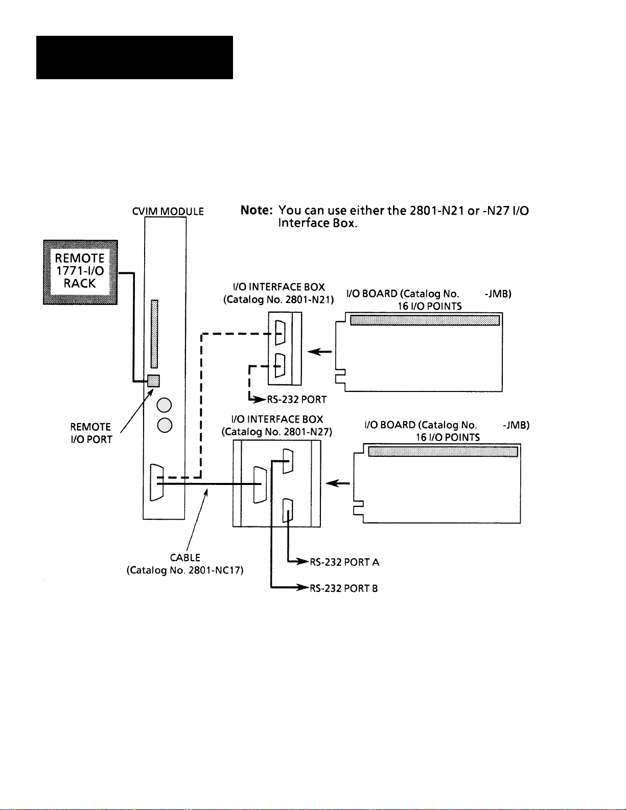
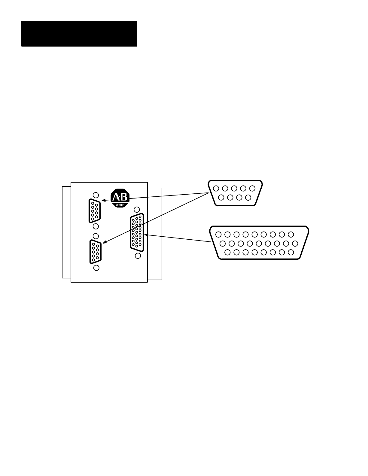
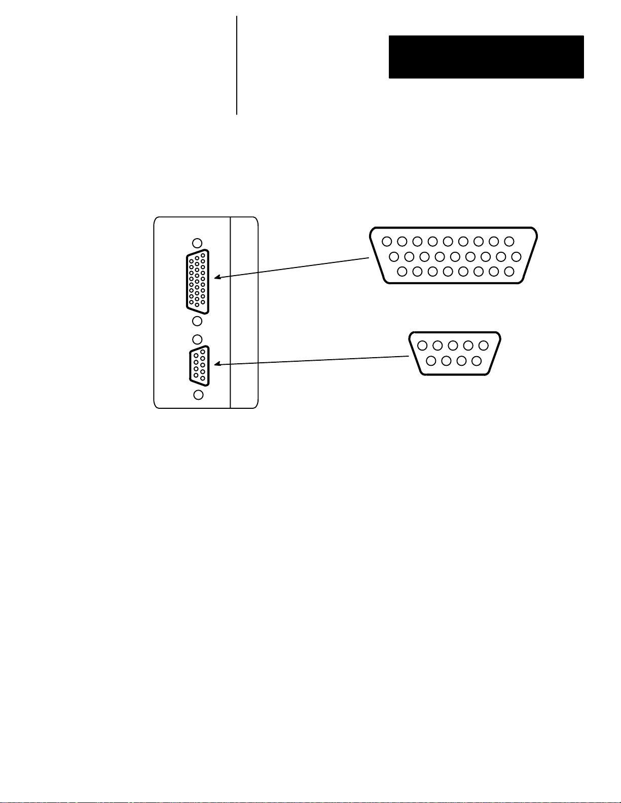
Figure 2.1
CVIM Module Communications Ports
However if you are using the 2801-N27
I/O Interface Box with CVIM Module Series A hardware,
only RS–232 port A is active.
1771
1771
2–2
Page 15

Chapter 2
Introduction
Remote I/O (Node Adapter)
RS–232 Ports
The remote I/O port (RIO) is located on the front of the CVIM module as
shown in Figure 2.1. Using the remote I/O port, you can connect the
following types of devices:
• Allen–Bradley Programmable Controllers (PLC–2, –3, and –5).
• Host Computers which have the Allen–Bradley IBM Bus Scanner
(Catalog No. 6008–SI). The 6008–SI bus scanner is compatible with the
A–B 6121/22 Industrial Computer, Industrial Terminal (Catalog Nos.
1784– T50, 1784–T35), or other IBM PC/AT compatible devices.
As shown in Figure 2.1, the RS–232 ports are located on the I/O Interface
Boxes (Catalog No. 2801–N21, –N27). The I/O Interface Box is connected to
the MODULE I/O port on the front of the CVIM module. Using the RS–232
interface(s) you can connect a variety of devices which use the RS–232
standard:
• Computers
• Operator Interfaces such as Allen–Bradley Industrial Computers and
Terminals with serial ports.
Local I/O
Pyramid Integrator Backplane
• I/O modules such as the Basic module (Catalog No. 1771–RB) or ASCII
module (Catalog No. 1771–DA).
• DATAMYTE and Dataliner (requires USER-PAK Software (Catalog No.
5370-UPK)
As shown in Figure 2.1, the local I/O consists of an I/O Board (Catalog No.
1771–JMB), I/O Interface Box (Catalog No. 2801–N21, –N27), an input and
up to 14 output modules as configured by the user. The Catalog No.
2801–NC17 cable connects the I/O interface box to the CVIM module.
Using the Pyramid Integrator backplane, you can directly communicate data
between the CVIM module and other devices installed in the Pyramid
Integrator chassis:
• Allen–Bradley PLC–5/250
• MicroVAX Information Processor
• Pyramid Integrator Resource Manager
2–3
Page 16

Chapter 2
Introduction
What Types of Information can be Communicated?
Discrete Bit Information
Depending upon the type of interface in use, you can access some or all of
the information listed below:
• Warning and Pass/Fail data.
• Numerical inspection results.
• Configuration data.
With each inspection that the CVIM module performs, individual bits are set.
There are 128 bits that can be read as inputs to a host device. These bits (part
of the inspection results) indicate:
• Master fault.
• Mastership.
• Configuration fault.
• Module Busy flag.
• Missed Trigger flag.
• Results Valid flag.
• Inspection Tool Pass/Fail/Warning flags.
There are 128 bits that can be set as outputs by a host device to control the
operation of the CVIM module. These bits control:
• Monitor display.
• Inspection trigger.
• Toolset selection.
• Enable/disable and force discrete I/O.
• Selection of operation after reject.
• Memory storage location. RAM, EEPROM, RAM Card, or external host
memory.
For more information on the 128 discrete input and 128 discrete output bits
Note:
refer to Appendix B.
2–4
Page 17

Chapter 2
Introduction
Results Blocks
Configuration Blocks
Communications Cables
The results data for each inspection are stored in Random Access Memory
(RAM) and overwrite the results of the previous inspection. The data stored
in results blocks contain information regarding reference windows,
inspection gages, inspection windows, etc. For a complete description of the
results blocks, refer to Appendix C.
The user developed inspection parameters of the CVIM module are stored in
the CVIM module’s memory as configuration blocks. This area of memory
can be read or manipulated through the Remote I/O port, RS–232 ports (A &
B) or Pyramid Integrator backplane. Refer to Appendix D for a complete
description of the configuration blocks and their contents.
If you are not using the Pyramid Integrator backplane for communications,
you will have to physically link the CVIM module to the host device. If you
need to create a communications cable, refer to the chapter that describes the
communications port you are using.
Memory Addressing
Depending upon how you access the CVIM module results and configuration
memory, you will have to address the data differently. If you refer to
Appendix A, B, and C you will notice that separate columns are provided for
Backplane, RS–232, and Remote I/O communications:
Note:
The RS–232 protocols (ASCII and DF1) do not access data using word and
bit addresses. Data is read/written in blocks. We have grouped the RS–232 and
Remote I/O ports together in Appendix B, C, and D (where appropriate) for your
convenience. You can ignore word and bit addresses if you are using the RS–232
ports (A & B).
2–5
Page 18
Chapter 2
Introduction
Memory Addressing (cont’d)
When you communicate through the Pyramid Integrator backplane all of the
data words are numbered consecutively and grouped in blocks. When you
use the Remote I/O port, you select a specific block and the first word in
each block is word #0.
Example of Addressing Results Block 1
Word Number
Pyramid Integrator Backplane RS–232 and Remote I/O
Toolset 1 Toolset 2
24-87 288-351
0–63
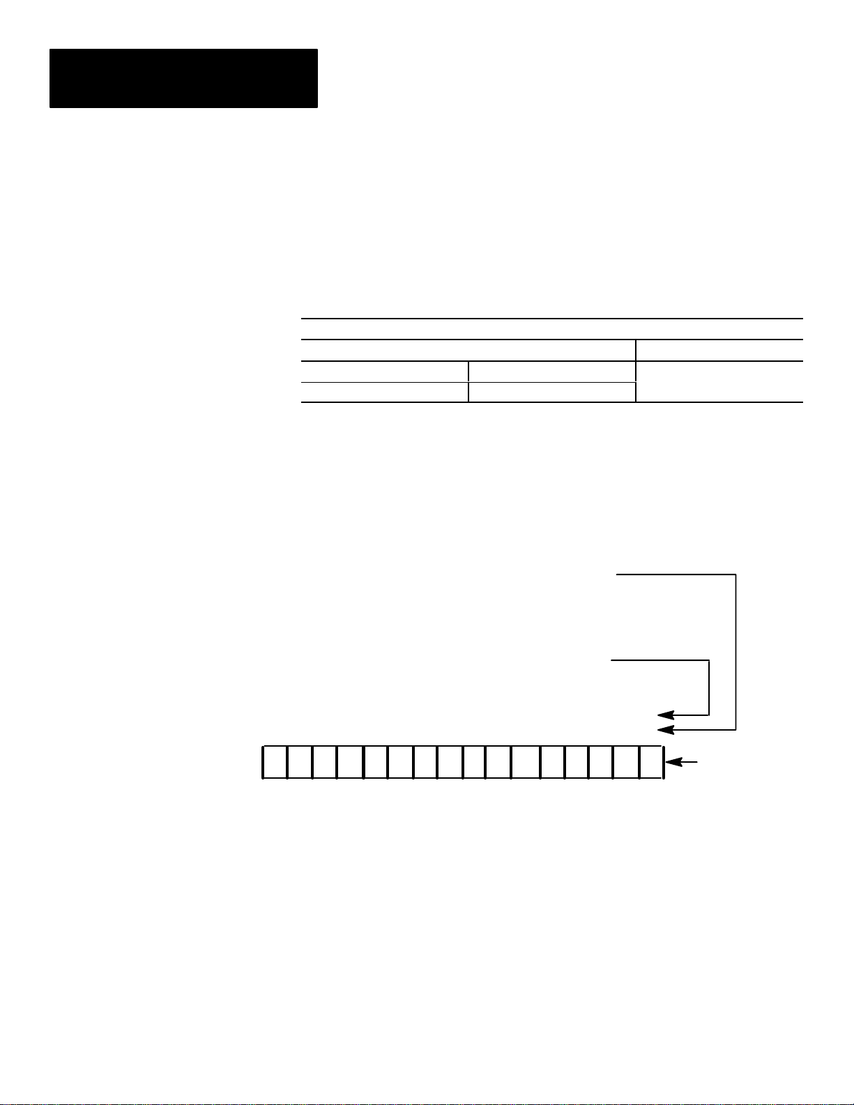
In addition, PLC I/O bit numbers are entered in octal format when
referencing 1771 I/O, while PLC files and backplane communications
specify a decimal bit number. Figure 2.2 illustrates how bits are numbered.
Figure 2.2
Bit Numbering
Bit Number if Accessing Data Through
Remote I/O as a 1771 I/O Rack. (Octal Value)
Bit Number if Accessing Data Through the Backplane
or Remote I/O Port Using Integer Files. (Decimal V alue)
15 14 13 12 11 10 9 8 7 6 5 4 3 2 1 0
17 16 15 14 13 12 11 10 7 6 5 4 3 2 1 0
1000100001001101
Example
Word
2–6
Page 19

Chapter 2
Introduction
Host Designation
Multiple Hosts
There are four communications ports which you can use simultaneously to
access CVIM module data (Remote I/O, RS–232 Ports A & B, and
Backplane). Only the host can issue commands to control the operation of
the CVIM module. You can read discrete bits and numerical results
information through any of the four communications ports, even through
non–host devices.
The CVIM module can operate with multiple hosts. You can select one host
to perform CVIM module/host configuration transfers, and another host to
perform all other CVIM/host operations. These two hosts are referred to as
the configuration host (CFG) and the system host (SYS). An example of
using multiple hosts is to select RS–232 A as the CFG host, and Remote I/O
as the SYS host.
Note: Any CVIM communications port can be used for reading results block
data regardless of whether or not the device connected to the port is selected
as a host.
Note: You can select the same host (Stand Alone, Pyramid, Remote I/O,
RS–232 A or B) as both the configuration host and the system host.
2–7
Page 20
Chapter
Chapter Objectives
Equipment Connections
A–B
3
Using Local I/O
The objectives of this chapter are to help you plan:
• The number of discrete output lines (up to 14) that your application will
require.
• The function that each output line will perform in your application.
• The assignment of analysis tool “results” to output lines.
• The assignment of status signals to output lines.
• The electrical and mechanical connections of the trigger (input) and
output lines to your production equipment.
The local I/O consists of:
• I/O Interface Box (Catalog No. 2801–N21, –N27)
• I/O Board (Catalog No. 1771–JMB)
• User specified I/O modules (plug into I/O board)
• Communications Cable (Catalog No. 2801–NC17)
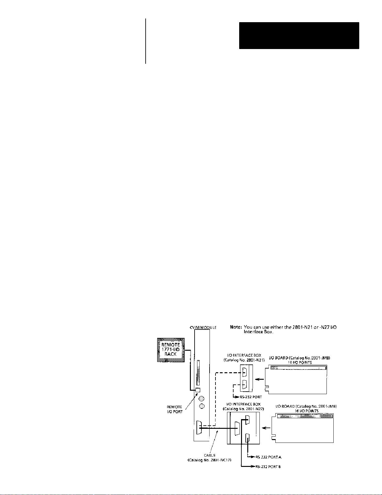
As shown in Figure 3.1, the communications cable (Catalog No.
2801–NC17) is connected to the MODULE I/O port on the front of the
CVIM module and the connector on the I/O Interface box. The I/O board
connector slides into the connector slot on the I/O Interface Box.
Figure 3.1
Local I/O Equipment Connections
A
3–1
Page 21

Chapter 3
Using Local I/O
Planning Output Line Assignments
Using the Output Line Planning Sheet
This section provides a planning sheet that you can use to lay out the function
and tool assignments for output lines.
The term “function assignment” refers to the type of signal information that
you want an output line to carry to your production equipment.
The term “tool assignment” refers to the tool(s) that you assign to an output
line.
Note: Tools can be assigned only to output lines that you have assigned a
“results” function. These output lines will carry the “pass/fail” results signals
from the tools during each inspection.
The next section, Planning Output Line Connections, provides electrical and
timing diagrams and data. You will need to use these diagrams to correctly
identify and connect the output lines to your production equipment.
The Output Line Planning Sheet is a form on which you can lay out your
plans for each output line. On this form you can account for:
• The 14 output lines.
• The six output line functions.
• The 64 gages and their warning and fault outputs.
• The 48 windows and their warning and fault outputs.
• The 6 reference tools and their “pass/fail” outputs.
• The light probe with its separate red, green, and blue warning and fault
outputs.
3–2
Page 22

Chapter 3
Using Local I/O
Here is an example of how an Output Line Planning Sheet could be filled
out:
Example CVIM Module Output Line Planning Sheet
Output Line Functions and Tool Assignments
Line Output Line
No. Function
1 Results 1 1 W 2 W 1 W 2 W
″ ″ ″ 3 W 4 W
2 Results 1 1 F 2 F 1 F 2 F
″ ″ ″ 3 F 4 F
3 Results 1 1 1
4 Results 1 A W
5 Results 1 A F
6 Results 2 1 W 1 F
″ ″ ″ 2 W 2 F
7 Strobe 1
8 Trig. NAK 1
9 Master Fault 1
10 Data Valid 1
11 Module Busy NA
12 Not Used
13 Not Used
14 Not Used
Tool
Set
Set
No.
No. Rng. No. Rng. No. Rng. No. Rng. Line Win. Cam. Rng.
Gage Window
Reference
Tool
Light Probe
The entries for the output lines have the following meanings:
• Output Line 1: The Results function is assigned to line 1. The Warning
Range results (W) for gages 1–4 and windows 1 and 2 of toolset #1 are
assigned to output line 1.
• Output Line 2: The Results function is assigned to line 2. The Fault
Range results (F) for gages 1–4 and windows 1 and 2 of toolset #1 are
assigned to output line 2.
• Output Line 3: The Results function is assigned to line 3. The “pass/fail”
results for reference line 1 of toolset #1 and reference window 1 are
assigned to line 3.
• Output Line 4: The Results function is assigned to line 4. The Warning
Range result from the camera A light probe is assigned to line 4. Camera
A is assigned to toolset #1.
3–3
Page 23

Chapter 3
Using Local I/O
Using the Output Line
Planning Sheet (cont’d)
• Output Line 5: The Results function is assigned to line 5. The Fault
Range result from camera A probe is assigned to line 5.
• Output Line 6: The Results function is assigned to line 6. The Warning
and Fault Range results for gages 1 and 2 of toolset #2 are assigned to
line 6.
• Output Line 7: The Strobe function for toolset #1 is assigned to line 7.
• Output Line 8: The Trigger NAK function for toolset #1 is assigned to
line 8.
• Output Line 9: The Master Fault function for toolset #1 is assigned to
line 9.
• Output Line 10: The Data Valid function for toolset #1 is assigned to line
10.
• Output Line 11: The Module Busy function is assigned to line 11. (Note
that this function does not relate to a toolset).
• Output Lines 12–14: These lines are not used.
Note: Output lines 1–6 are assigned the Results function. These lines will
carry “pass/fail” results from the analysis tools to your production
equipment. Lines 7–11 are assigned other functions. Lines 12–14 are not
used.
Here is a brief explanation of the signal functions that you can assign to the
output lines:
• Module Busy: This signal goes high when the CVIM system enters the
configuration mode and during a configuration download operation.
Module Busy goes low when the system enters the run mode (whether or
not triggers are present).
You can assign the Module Busy function to only one output line.
Note: When configurations are being downloaded to the CVIM module, the
module busy signal at the JMB board is not active.
3–4
Note: All of the remaining signal functions (except Strobe, Module Busy,
and Trigger NAKs) can be configured to produce a pulse whose duration
depends on the number of milliseconds that you assign to the Duration/1 or
Duration/2 parameter. (The ‘‘1’’ and ‘‘2’’ designate toolset #1 and toolset
#2).
• 1/Results: This signal occurs when the results of a tool inspection exceed
the warning and/or fault limits. (The tool must be assigned to an output
line that has already been assigned the Results function.)
Page 24

Chapter 3
Using Local I/O
You can assign the Results signal function to any unassigned output line.
As noted above, the 1/Results signal function must be assigned to an output
line before any tool can be assigned to that line. Thus, if you wanted
inspection results from Ref. Line # 2 to be assigned to output line #10, you
would first have to assign the Results signal function to output line #10.
Note: You can assign the inspection results from any tool in toolset #1 to an
output line to which you have already assigned the 1/Results signal function.
• 1/Data Valid: This signal occurs when the CVIM system has completed an
inspection using toolset #1. 1/Data Valid signals (the “data”) are stable on
all output lines assigned to the 1/Results signal function. 1/Data Valid
goes low during the next inspection.
Note: 1/Data Valid does not indicate whether an inspection has passed or
failed. That is the task of the output lines assigned to the 1/Results signal
function.
You can assign the 1/Data Valid function to only one output line.
• 1/Trigger NAK: This signal occurs when the CVIM system receives a
trigger input signal for toolset #1, but cannot process that trigger. The
signal goes low upon the next “accepted trigger”.
You can assign the 1/Trigger NAK function to only one output line.
• 1/Master Fault: This signal occurs when any (one or more) analysis tools
in the CVIM system detects a Fail condition.
You can assign the 1/Master Fault function to only one output line.
• 1/Strobe: This signal is used to trigger the strobe flash unit (if used). The
signal occurs within 1 ms after the CVIM system receives a trigger input
signal.
You can assign the 1/Strobe function to only one output.
• 1/Duration (n)ms: From 1msec to 2000msec. This value determines the
pulse duration, in milliseconds of all pulse–type signals. A setting of zero
means the signal will remain in its present state until updated by a
subsequent inspection.
Note: The output duration may vary if subsequent inspections occur before
the specified output duration has elapsed.
In your application, the function and tool assignment(s) for each output line
will of course depend on the specific requirements of your production
equipment.
You will find a full–page, blank copy of the planning sheet on the last page
of this chapter. We suggest that you do not mark that page, but use it instead
as a copy master, and use the copies to prepare your output line plans.
3–5
Page 25
Chapter 3
Using Local I/O
Using the Output Line
Planning Sheet (cont’d)
Using Output Signal Timing Data
Keep in mind that a completed planning sheet can serve also as a record of
your output line usage. You may find it desirable to store your filled–out
planning sheets in a file folder or loose leaf binder.
To make proper use of the signal data available to the output lines, you must
first understand the timing relationships that exist between the trigger input
signal (which starts each inspection cycle) and the output signals.
Knowing these signal timing relationships enables you to accurately
synchronize the inspection cycles with your production equipment.
Timing charts (Figures 3.2, 3.3, and 3.4) show the timing relationships in
various circumstances.
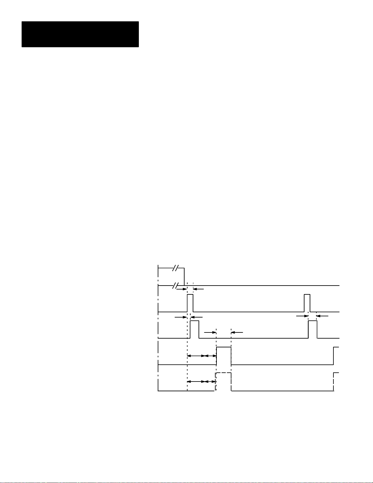
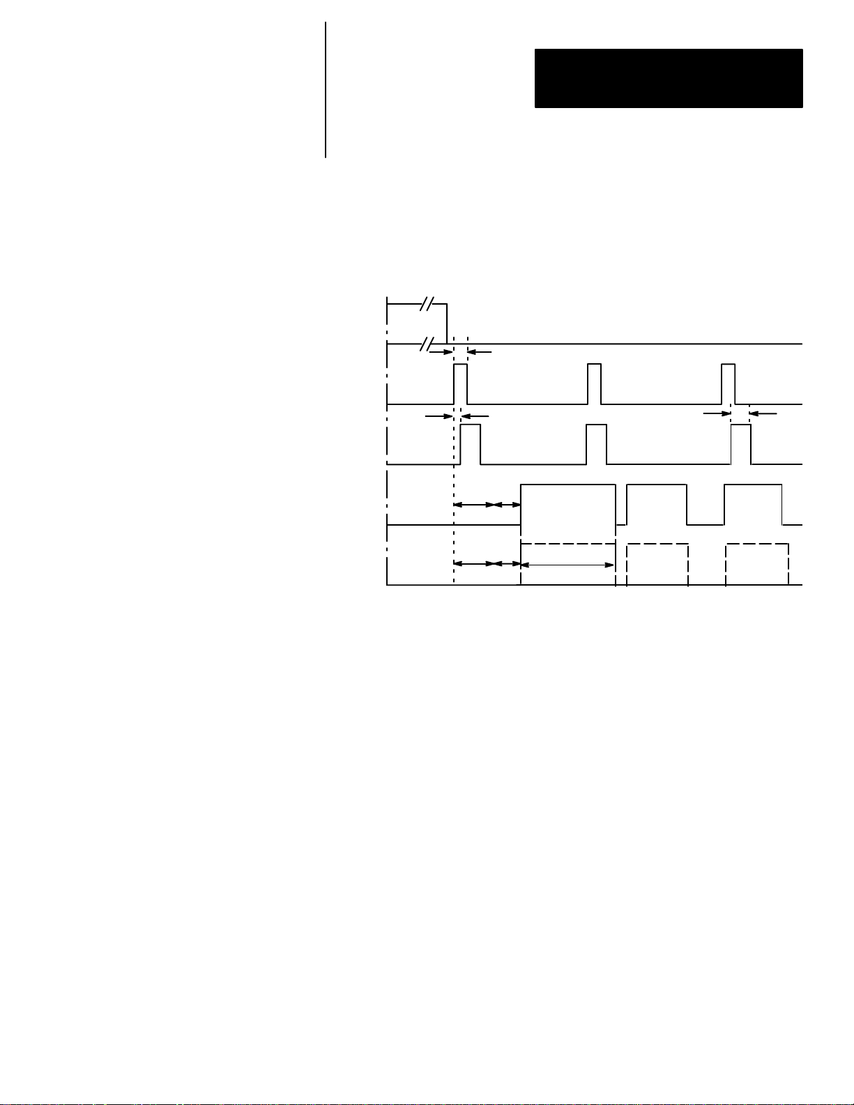
Figure 3.2 shows the relationship between the trigger leading edge and the
Strobe, Data Valid, and Results signals, where the last three appear as pulses
whose duration you determine during configuration.
Figure 3.2
Timing Diagram — Pulsed I/O
MODULE
BUSY
Min. trigger ≈ 2ms*
Trigger
(Input)
STROBE
DATA
VALID
RESULTS
** Minimum acquisition time: 17ms for 256x256 and 512x256 Res; 34 ms for 512x512 res.
*** Analysis time (variable).
Trigger
pulse #1
Max. lag ≈ 1ms
***
***
Min. strobe ≈ 1ms
You can select a
pulse width of 1
to 2000ms
DATA VALID will always
pulse high when inspection
processing is complete.
RESULTS signal will pulse
high if an analysis tool
range limit is exceeded.
Trigger
pulse #2
3–6
Page 26
Chapter 3
Using Local I/O
Using Output Signal
Timing Data (cont’d)
In Figure 3.3, trigger pulse #2 occurs before the CVIM module has finished
processing the inspection cycle started by trigger pulse #1.
Figure 3.3
Timing Diagram — Trigger #2 During Data Valid, Pulsed I/O
MODULE
BUSY
Trigger
(Input)
STROBE
DATA
VALID
RESULTS
Min. trigger ≈ 2ms*
Trigger
pulse #1
Max. lag ≈ 1ms
** ***
***
DATA VALID will always pulse high when
inspection processing is complete
Trigger
pulse #2
Min. Strobe ≈ 1ms
For Trigger #1
You can select
a pulse width of
1 to 2000 ms
***
For Trigger #2 For Trigger #3
Trigger
pulse #3
** Minimum acquisition time: 17ms for 256x256 and 512x256 Res; 34 ms for 512x512 res.
*** Analysis time (variable).
****RESULTS will pulse high if an analysis tool range is exceeded.
3–7
Page 27
Chapter 3
.
Using Local I/O
Using Output Signal
Timing Data (cont’d)
Whenever these signals go high, they will go low again at the end of the
specified pulse duration (1 to 2000ms).
Note: The Local I/O Module Busy is high only during system configuration.
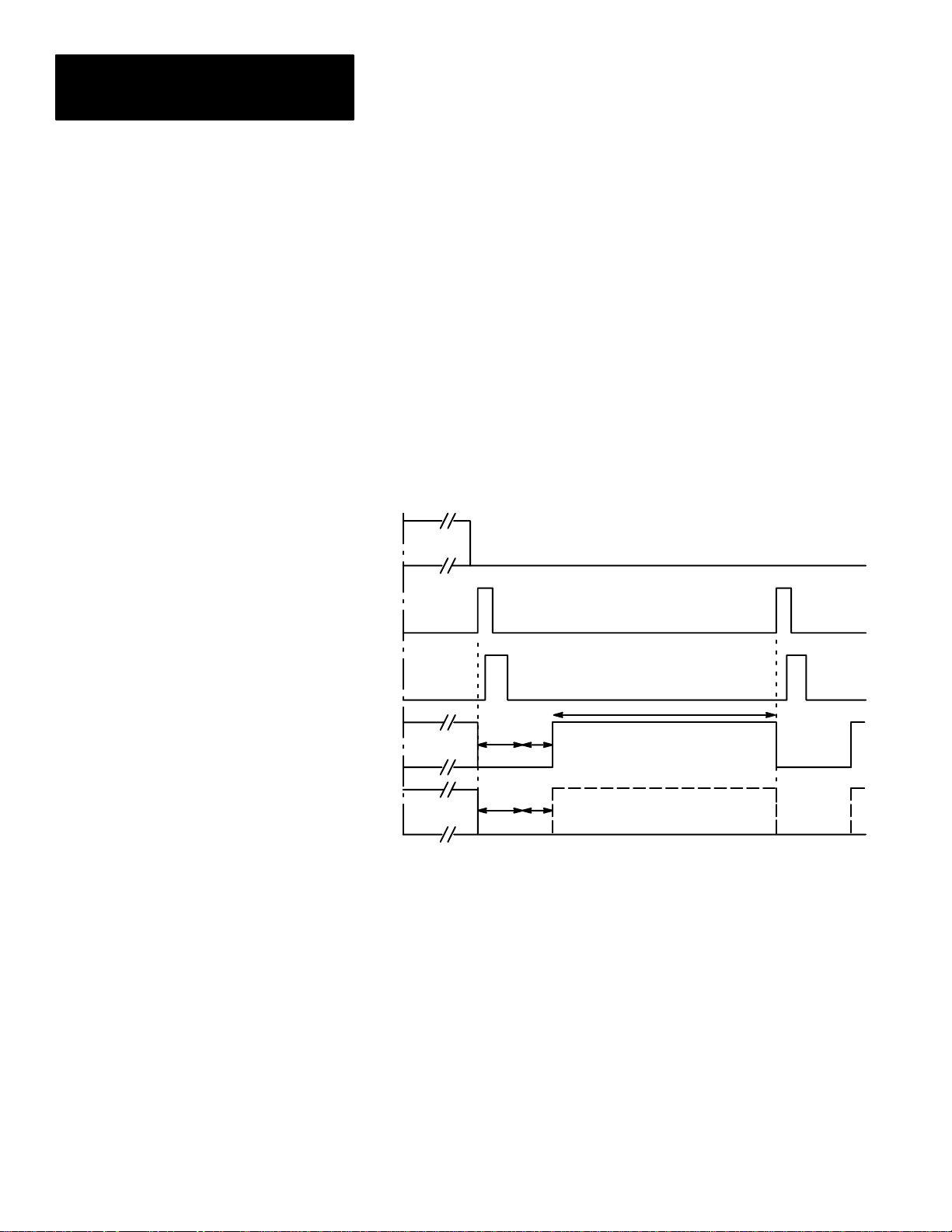
In Figure 3.4, the Data Valid, and Results signals appear as changes in signal
levels. This will occur if, during system configuration, you select a pulse
“duration” of 0 (zero) milliseconds. Data Valid will stay high until the
leading edge of the next valid trigger signal (Trigger Pulse #2). Results stay
in their current state until the leading edge of the next Trigger pulse, then
change depending upon the results.
Figure 3.4
Timing Diagram — Non–Pulsed I/O
MODULE
BUSY
Trigger
(Input)
Trigger
pulse #1
Trigger
pulse #2
STROBE
DATA
VALID
RESULTS
** *
DATA VALID will go high when inspection
***
***
Minimum acquisition time: 17ms for 256x256 Res.; 34ms for 512x512 Res
*
Analysis time.
**
Data Valid (and results) will be sent for a minimum of 15 msec when 0
** *
pulse length is selected.
processing is complete, and will go low with the
leading edge of the next valid trigger.
RESULTS signal will go
high if an analysis tool
range limit is exceeded.
3–8
Page 28
Chapter 3
Using Local I/O
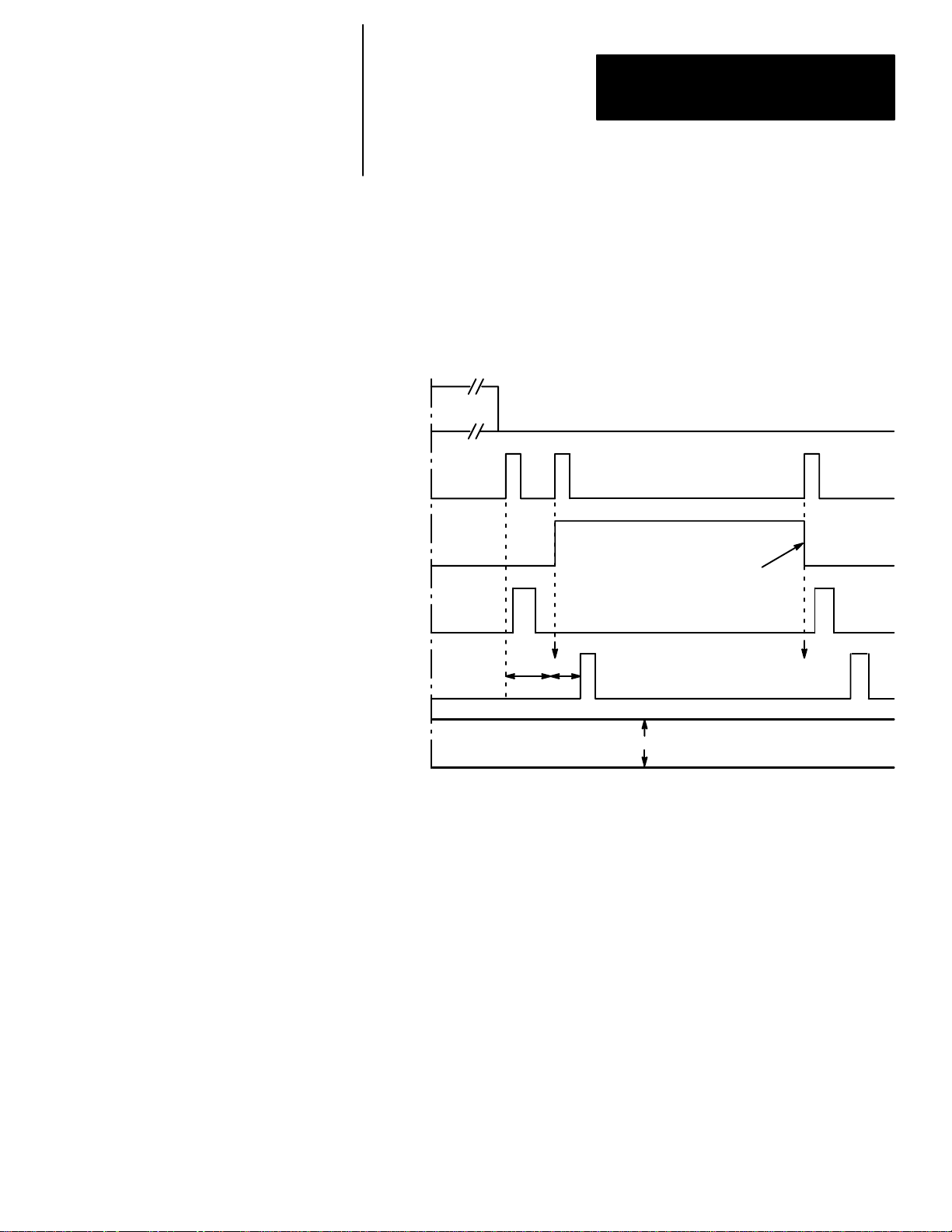
In Figure 3.5, trigger pulse #2 occurs before the CVIM system is finished
processing the inspection cycle started by trigger pulse #1. This causes the
Trigger NAK signal to go high. Trigger NAK will stay high until leading
edge of the next valid trigger pulse (trigger pulse #3).
Figure 3.5
Timing Diagram– Missed Trigger
MODULE
BUSY
Trigger
(Input)
TRIGGER
NAK
STROBE
DATA
VALID
RESULTS
Trigger
pulse #1
Trigger
pulse #2
TRIGGER NAK goes high because trigger 2 cannot be
processed. (Trigger 1 processing is not yet complete.)
TRIGGER NAK goes low because trigger 3
can be processed. (Trigger 1 processing is
now complete.)
*Min. processing time:
17ms, 256x256 Res.
***
Results stay in their current state, hihg or low.
17ms, 512x256 Res.
34ms, 512x512 Res.
**Analysis time.
Trigger
pulse #3
3–9
Page 29
Chapter 3
Using Local I/O
Planning Output Line Connections
Connections to RS–232 Ports
(2801–N27 Interface Box)
P
O
R
T
A
P
O
R
T
B
This section provides diagrams of electrical connections for correctly
connecting your production equipment to the CVIM module’s discrete output
and RS–232 lines.
Figure 3.6 shows the cable connectors and their pin numbers on the I/O
Interface Box (Catalog No. 2801–N27).
Figure 3.6
Pinouts– I/O Interface Box (Catalog No. 2801–N27)
1
2345
789
6
Cable connectors to
RS–232 devices.
C
V
I
M
18
Cable connector from Module
I/O connector on CVIM Module.
1
2345671089
11121314151617
19
20212223242526
3–10
I/O Interface Box (Catalog No.
2801–N27)
Page 30
Chapter 3
Using Local I/O
Connections to RS–232 Port
(2801–N21 Interface Box)
I/O Interface Box (Catalog No. 2801–N21)
Figure 3.7 shows the cable connectors and their pin numbers on the I/O
Interface Box (Catalog No. 2801–N21).
Figure 3.7
Pinouts– I/O Interface Box (Catalog No. 2801–N21)
8
9
18
Cable connector from Module
I/O connector on CVIM Module.
2345
789
6
Cable connectors to
RS–232 devices.
1
234567
10
11121314151617
19
20212223242526
1
3–11
Page 31

Chapter 3
Using Local I/O
CVIM Module I/O Interface Box Connections
Tables 3.A through 3.H show the connector pin assignments with the various
combinations of Series A and Series B CVIM modules connected to I/O
Interface Boxes (Catalog Nos. 2801–N21, –N27) .
Table 3.A
CVIM Module I/0 Connector: Series A CVIM Module
Pin Number Function Pin Number Function
1 Trigger Input Line #1 14 Output Line #12
2 Trigger Input Line #2 15 Output Line #13
3 Output Line #1 16 Output Line #14
4 Output Line #2 17 Reserved
5 Output Line #3 18 Reserved
6 Output Line #4 19 Ground (Power)
7 Output Line #5 20 Ground (Power)
8 Output Line #6 21 Ground (Chassis)
9 Output Line #7 22 Ground (Signal)
10 Output Line #8 23
11 Output Line #9 24
12 Output Line #10 25
13 Output Line #11 26
TXD (Transmit
Data: RS–232 A)
RTS (Request to Send:
RS–232 A)
RXD (Receive
Data: RS–232 A)
CTS (Clear to Send:
RS–232 A)
3–12
Page 32

Chapter 3
Using Local I/O
Table 3.B
CVIM Module I/0 Connector: Series B CVIM Module
Pin Number Function Pin Number Function
1
2
3 Output Line #1 16 Output Line #14
4 Output Line #2 17 Reserved
5 Output Line #3 18 Reserved
6 Output Line #4 19 Ground (Power)
7 Output Line #5 20 Ground (Power)
8 Output Line #6 21 Ground (Chassis)
9 Output Line #7 22 Ground (Signal)
10 Output Line #8 23
11 Output Line #9 24
12 Output Line #10 25
13 Output Line #11 26
Trigger Input
Line #1
Trigger Input
Line #2
14 Output Line #12
15 Output Line #13
TXD (Transmit
Data: RS–232 A)
TXD (Transmit
Data: RS–232 B)
RXD (Receive
Data: RS–232 A)
RXD (Receive
Data: RS–232 B)
Table 3.C
I/O Interface Box (Catalog No. 2801–N21):
RS–232 Connector with Series A CVIM Module
Pin Number Function Pin Number Function
1 No Connection 6 No Connection
2
3
4 Ground (Chassis) 9 No Connection
5 Ground (Signal)
RXD (Receive
Data: RS–232 A)
TXD (Transmit
Data: RS–232 A)
7
8
RTS (Request to
Send: RS–232 A)
Send: RS–232 A)
Table 3.D
I/O Interface Box (Catalog No. 2801–N21):
RS–232 Connector with Series B CVIM Module
Pin Number Function Pin Number Function
1 No Connection 6 No Connection
2
3
4 Ground (Chassis) 9 No Connection
5 Ground (Signal)
RXD (Receive
Data: RS–232 A)
TXD (Transmit
Data: RS–232 A)
7
8
TXD (Transmit
Data: RS–232 B)
RXD (Receive
Data: RS–232 B)
CTS (Clear to
3–13
Page 33

Chapter 3
Using Local I/O
CVIM Module I/O
Interface Box Connections
(cont’d)
Table 3.E
I/O Interface Box (Catalog No. 2801–N27)
RS–232 Port A Connector Series A CVIM Module
Pin Number Function Pin Number Function
1 No Connection 6 No Connection
2
3
4 + 5V DC 9 No Connection
5 Ground (Signal)
RXD (Receive
Data: RS–232 A)
TXD (Transmit
Data: RS–232 A)
7 + 5V DC
8 No Connection
Table 3.F
I/O Interface Box (Catalog No. 2801–N27):
RS–232 Port B Connector Series A CVIM Module
Pin Number Function Pin Number Function
1 No Connection 6 No Connection
2
3
4 + 10V DC 9 No Connection
5 Ground (Signal)
CTS (Clear to
Send: RS–232 A)
RTS Request to
Send: RS–232 A)
7 + 10V DC
8 No Connection
3–14
Table 3.G
I/O Interface Box (Catalog No. 2801–N27):
RS–232 Port A Connector Series B CVIM Module
Pin Number Function Pin Number Function
1 No Connection 6 No Connection
2
3
4 + 5V DC 9 No Connection
5 Ground (Signal)
RXD (Receive
Data: RS–232 A)
TXD (Transmit
Data: RS–232 A)
7 + 5V DC
8 No Connection
Page 34

Chapter 3
Using Local I/O
Table 3.H
I/O Interface Box (Catalog No. 2801–N27):
RS–232 Port B Connector Series B CVIM Module
Pin Number Function Pin Number Function
1 No Connection 6 No Connection
2
3
4 + 10V DC 9 No Connection
5 Ground (Signal)
RXD (Receive
Data: RS–232 B)
TXD (Transmit
Data: RS–232 B)
7 + 10V DC
8 No Connection
Connections to
1771–JMB Interface
The 1771–JMB interface board is designed for direct edge connection to the
I/O Interface Box, Catalog Nos. 2801–N21, –N27.
If you intend to use the 1771–JMB board and the I/O Interface Box, you will
need to know the relationship between the discrete I/O line numbers and the
LED numbers, the optic–isolator type, and the terminal block screws
numbers on the 1771–JMB board. These are shown in the figure and table
that follows.
To power the JMB logic components, you must connect an external +5VDC
power supply to the (+) and (–) terminals screws shown in the board layout
Figure 3.5.
3–15
Page 35

Chapter 3
ЛЛЛЛЛЛЛЛЛЛ
ЛЛЛЛЛЛЛЛЛЛ
Using Local I/O
Connections to
1771–JMB Interface
(cont’d)
CVIM
Module
Overlay
T
R
I
1
G
G
E
2
R
S
1
2
3
Figure 3.8 shows the layout of the 1771–JMB interface board and the
adhesive–backed overlay.
Figure 3.8
Local I/O Board ( Catalog No. 1771–JMB).
Teminal screws for external
+5VDC power supply
0 1 2 3 4 5 6 7 9 10 11 12 13 14 15
In
+
–
1 2 3 4 5 6 7 8 9 10 11 1213 14 15 16 17 18 19 20 21 22 2324 26 27 28 29 30 31 32
Not Used
Out
Out
Out
O
U
U
4
5
T
6
P
T
7
S
8
8
9
10
11
13
13
14
Out
Out
Out
Out
Out
Out
Out
Out
Out
Out
Out
25
3–16
Page 36

Chapter 3
Using Local I/O
Table 3.I shows the relationship between the I/O line and optic–isolator
numbers shown in Figure 3.8.
Table 3.I
Output Numbering
Discrete I/O
Line Number
Input Output
1 0 1 2
2 1 3 4
1 2 5 6
2 3 7 8
3 4 9 10
4 5 11 12
5 6 13 14
6 7 15 16
7 8 17 18
8 9 19 20
9 10 21 22
10 11 23 24
11 12 25 26
12 13 27 28
13 14 29 30
14 15 31 32
LED and I/O
Module
Module
Number
Terminal Screw
and Polarity
+ –
Note: A self–adhesive decal (Part Number 40062-149-01) is provided with
the 1771–JMB Local I/O board. This decal identifies the I/O lines. Use the
chart on the next page if the decal is not in place.
3–17
Page 37

Chapter 3
Using Local I/O
OUTPUT LINE PLANNING SHEET
Output Line Functions and Assignments
Line Output Line
No. Function
Gage Window
No. Rng. No. Rng. No. Rng. No. Rng. Line Win. Red Green Blue
Reference
Tool
Light Probe
3–18
Page 38

Chapter
Using the Remote I/O Link
4
Chapter Objectives
Remote I/O Communications
In this chapter we provide:
• Basic description of Remote I/O communications.
• Connection diagrams.
• Description of CVIM module setup requirements.
• Three example PLC programs for accessing CVIM module data.
• An example 6008–SI program.
As stated earlier, the Remote I/O port is located on the front of the CVIM
module and is labeled RIO. This port allows the CVIM module to become a
link in an Allen–Bradley Remote I/O network which can be up to 10,000 feet
long. Data on the network can be transmitted at baud rates as high as 230K.
Maximum Link Length (Feet) Baud Rate
10,000 57.6K
5,000 115.2K
2,500 230.4K*
* Only applies to communications between PLC-5/250 controllers in other racks.
Use twin–axial cable (Catalog No. 1770–CD) to connect the CVIM module
to other devices. This cable connects to the Remote I/O port (labeled RIO)
and the next device on the network. Refer to Figures 4.1 through 4.8 for
connection diagrams.
4–1
Page 39

Chapter 4
Using the Remote I/O Link
(Node Adapter)
Remote I/O Communications
(cont’d)
Figure 4.1
PLC–5 to CVIM Module– Remote I/O Link
1771 I/O Rack
PLC
5/15
5/25
5/30
5/40
5/60
Catalog No.
1770–CD
Cable
Figure 4.2
6008 SI IBM PC/AT Scanner to CVIM Module– Remote I/O Link
6008 SI I/O Scanner
IBM PC/AT
CVIM Module
RIO
CVIM Module
Catalog No.
1770–CD
Cable
Figure 4.3
6008 SV VME Scanner to CVIM Module– Remote I/O Link
6008 SV I/O Scanner
Host
Computer
Catalog No.
1770–CD
Cable
RIO
CVIM Module
RIO
4–2
Page 40

Chapter 4
Using the Remote I/O Link
(Node Adapter)
Remote I/O Communications
(cont’d)
Figure 4.4
6008 SQH1/2 Q–BUS Scanner to CVIM Module–Remote I/O Link
CVIM Module
6008 SQH1/2 I/O Scanner
Host
Computer
Catalog No.
1770–CD
Cable
Figure 4.5
Mini PLC–2 to CVIM Module– Remote I/O Link
1771 I/O Rack
MINI PLC–2
2/02
2/15
2/16
2/17
Catalog No. 1771–SN
Sub I/O Scanner Module
Catalog No.
1770–CD
Cable
CVIM Module
RIO
RIO
Figure 4.6
PLC–2 to CVIM Module– Remote I/O Link
Catalog No. 1772–CS
Cable
PLC–2/20
–2/30
Catalog No.1771–CJ/CK
Power Cable
Catalog No.
1772–SD2
Scanner
Distribution
Module
Catalog No.
1770–CD
Cable
CVIM Module
RIO
4–3
Page 41

Chapter 4
Using the Remote I/O Link
(Node Adapter)
Remote I/O Communications
(cont’d)
Figure 4.7
PLC–3 to CVIM Module–Remote I/O Link
Catalog No. 1775–
S4A/S4BS5/SR/SR5
PLC–3
I/O Scanners
Catalog No.
1770–CD
Cable
Figure 4.8
PLC–5/250 to CVIM Module– Remote I/O Link
Pyramid Integrator
Rack
Remote Scanner
PLC–5/250
Catalog No.
1770–CD
Cable
CVIM Module
RIO
CVIM Module
RIO
4–4
Page 42

Chapter 4
Using the Remote I/O Link
(Node Adapter)
Remote I/O Communications
(cont’d)
2801
Figure 4.9
Typical Hardware Layout for Remote I/O
2705–P11J1 RediPANEL
Note: You can also read the data valid signal over the remote I/O link.
4–5
Page 43

Chapter 4
Using the Remote I/O Link
(Node Adapter)
Remote I/O Communications
(cont’d)
What Functions can be Performed over the Remote I/O Network?
When installed on a Remote I/O network, the CVIM module acts as a slave
device. Another device such as a PLC or computer will act as a host device.
This means that the CVIM module will not initiate the sending of any data
until a request is made by the host. To a host device, the CVIM module will
appear simultaneously as both a full I/O rack on the network (128 input bits
and 128 output bits) and as an intelligent module with block transfer
capability in group 0, slot 0 in the same rack. Refer to Appendix B for a
description of discrete bit data.
Note: If the CVIM module is the last node on a network, you must terminate
the communication line (refer to Figure 4.9 for an example).
A hist link can request or manipulate the following data over the Remote I/O
link:
• Obtain CVIM module inspection result information. Refer to Appendix B
& C.
• Upload or download CVIM module configurations for inspections. Refer
to Appendix D.
• Issue Configuration Read/Write commands between the following CVIM
module memory locations:
CVIM module Random Access Memory (RAM) and CVIM module
Electrically Erasable Programmable Only Memory (EEPROM). RAM is
volatile and EEPROM is non-volatile.
CVIM module RAM and RAM card. The RAM card slides into a slot on
front of the CVIM module.
CVIM module RAM and host memory.
• Change run-time display menus.
• Enable/Disable local I/O board.
• Force local I/O On or Off.
4–6
Page 44

Chapter 4
Using the Remote I/O Link
(Node Adapter)
Obtaining Inspection Result Information
CVIM Module Configuration Instructions
You can obtain inspection result information for each of the inspection tools
over the Remote I/O link. There are two levels of access to this information:
• Discrete Bits. These bits indicate pass/fail/warning data.
• Result Data Words. These words contain actual inspection result data such
as measured lengths, number of black pixels, etc.
Note: Refer to Appendix B for a description of the discrete bit results and
Appendix C for a description of numerical results data blocks.
If you are using the Remote I/O link to communicate with a PLC–2, –3, or
–5 (or PLC–5/250 in another rack), you must configure the CVIM module as
follows:
Select the Remote I/O port for communications:
Note: This step is not required if you are only reading results.
4. Select the setup menu <Setup>.
5. Select the environment menu <Envirn>.
6. Select the system menu <System>.
7. Select a Host menu <CFG Host> or <SYS Host>.
8. Select remote I/O option <Remote I/O>.
Note: Unless a separate configuration host is being used, set both the CFG
Host & SYS Host for Remote I/O.
Configure CVIM module I/O parameters:
9. Select the I/O menu <I/O>.
10.Select <1771 Remote I/O> option.
11.Enable the Remote I/O port by selecting <Enabled>.
12.Select the rack address (octal) using the keypad.
13.Select the baud rate <57.6Kbaud> or other options.
Select the CVIM module trigger source:
14.Select the trigger source menu <Toolset>.
15.Select the trigger source menu for the appropriate toolset <Trigger
Source>.
16.Select either <I/O>, <Hosted>, or <Internally Triggered> trigger sources.
Note: The example connection diagram shown on Figure 4.9 shows a trigger
using the local I/O board.
4–7
Page 45

Chapter 4
Using the Remote I/O Link
(Node Adapter)
Accessing Discrete Bit Information
A PLC can directly access discrete bit information using a simple ladder
program. For example:
You can use the following rung to examine the data valid bit and energize an
output if the data is valid. Refer to Chapter 3 for a description of the local
I/O. This example assumes that the CVIM module is in Rack 02 and the
output device is in Rack 01.
Although the same basic information is provided in Appendix B, Tables 4.A
and 4.B illustrate the word and bit locations of the discrete bits that can be
read or manipulated using simple ladder programs. We have organized the
data so that it is formatted similar to a PLC setup screen. Table 4.A shows
the CVIM module Remote Inputs (CVIM module to PLC) if the CVIM
module is rack 02. Table 4.B shows the CVIM module Remote Outputs
(PLC to CVIM module) if the CVIM module is rack 02.
Important Note: To read results data, you must set one of the following bits
(assuming CVIM module is rack 02):
• O:22/00 (Post First Part of Results to Remote I/O)
• O:22/01 (Post Second Part of Results to Remote I/O)
Note to PLC–2 Users:
When you use any PLC–2 family processor with the CVIM module, you
should understand the operation of the PLC Block Transfer Done bits for
Read and Write instructions. PLC–2 family processors use the input image
table for these bits, all other PLCs can specify integer files for this function.
This means that a PLC–2 user must use proper programming techniques to
avoid confusion between the following bits:
• CVIM module discrete I/O input word 0, bit 6 (data valid toolset#1) and
bit 7 (data valid toolset#2).
• PLC–2 family input image table word 0, bit 6 (BTW done bit) and bit 7
(BTR done bit).
4–8
Page 46

Chapter 4
21
22
23
24
25
26
27
Using the Remote I/O Link
(Node Adapter)
Accessing Discrete
Bit Information (cont’d)
07
–––
17
(Not used)
1 = Master
Fault
1 = Window 4
Fault
1 = Window 8
Fault
1 = Window
12 Fault
1 = Window
16 Fault
1 = Window
20 Fault
1 = Window
24 Fault
06
–––
16
1=Data Valid 0=First Bits
1 = Light
Probe Failed
1 = Window 4
Warning
1 = Window 8
Warning
1 = Window
12 Warning
1 = Window
16 Warning
1 = Window
20 Warning
1 = Window
24 Warning
05
–––
15
Results
1 = Reference
Window 3
Failed
1 = Window 3
Fault
1 = Window 7
Fault
1 = Window
11 Fault
1 = Window
15 Fault
1 = Window
19 Fault
1 = Window
23 Fault
Table 4.A
CVIM Module Remote I/O Inputs (CVIM Module to PLC) if CVIM Module is Rack 02
BIT
04
–––
14
1 = Trigger
Missed
1 = Reference
Window 2
Failed
1 = Window 3
Warning
1 = Window 7
Warning
1 = Window
11 Warning
1 = Window
15 Warning
1 = Window
19 Warning
1 = Window
23 Warning
03
–––
13
1 = Module
Busy
1 = Reference
Window 1
Failed
1 = Window 2
Fault
1 = Window 6
Fault
1 = Window
10 Fault
1 = Warning
14 Fault
1 = Window
18 Fault
1 = Window
22 Fault
02
–––
12
1 = PLC is
Master
1 = Reference
Line 3 Failed
1 = Window 2
Warning
1 = Window 6
Warning
1 = Window
10 Warning
1 = Window
14 Warning
1 = Window
18 Warning
1 = Window
22 Warning
01
–––
11
1 = Config.
Error
1 = Reference
Line 2 Failed
1 = Window 1
Fault
1 = Window 5
Fault
1 = Window 9
Fault
1 = Window
13 Fault
1 = Window
17 Fault
1 = Window
21 Fault
00
–––
10
(Not Used)
1 = Reference
Line 1 Failed
1 = Window 1
Warning
1 = Window 5
Warning
1 = Window 9
Warning
1 = Window
13 Warning
1 = Window
17 Warning
1 = Window
21 Warning
W
O
R
D
20
1 = Gage 4
Fault
1 = Gage 8
Fault
1 = Gage 12
Fault
1 = Gage 16
Fault
1 = Gage 20
Fault
1 = Gage 24
Fault
1 = Gage 28
Fault
1 = Gage 32
Fault
1 = Gage 4
Warning
1 = Gage 8
Warning
1 = Gage 12
Warning
1 = Gage 16
Warning
1 = Gage 20
Warning
1 = Gage 24
Warning
1 = Gage 28
Warning
1 = Gage 32
Warning
1 = Gage 3
Fault
1 = Gage 7
Fault
1 = Gage 11
Fault
1 = Gage 15
Fault
1 = Gage 19
Fault
1 = Gage 23
Fault
1 = Gage 27
Fault
1 = Gage 31
Fault
1 = Gage 3
Warning
1 = Gage 7
Warning
1 = Gage 11
Warning
1 = Gage 15
Warning
1 = Gage 19
Warning
1 = Gage 23
Warning
1 = Gage 27
Warning
1 = Gage 31
Warning
1 = Gage 2
Fault
1 = Gage 6
Fault
1 = Gage 10
Fault
1 = Gage 14
Fault
1 = Gage 18
Fault
1 = Gage 22
Fault
1 = Gage 26
Fault
1 = Gage 30
Fault
1 = Gage 2
Warning
1 = Gage 6
Warning
1 = Gage 10
Warning
1 = Gage 14
Warning
1 = Gage 18
Warning
1 = Gage 22
Warning
1 = Gage 26
Warning
1 = Gage 30
Warning
1 = Gage 1
Fault
1 = Gage 5
Fault
1 = Gage 9
Fault
1 = Gage 13
Fault
1 = Gage 17
Fault
1 = Gage 21
Fault
1 = Gage 25
Fault
1 = Gage 29
Fault
1 = Gage 1
Warning
1 = Gage 5
Warning
1 = Gage 9
Warning
1 = Gage 13
Warning
1 = Gage 17
Warning
1 = Gage 21
Warning
1 = Gage 25
Warning
1 = Gage 29
Warning
4–9
Page 47

Chapter 4
21
23
25
26
27
Using the Remote I/O Link
(Node Adapter)
Accessing Discrete
Bit Information (cont’d)
07
–––
17
(Reserved)***
(Not Used)
(Not Used)
(Not Used) (Not Used) (Not Used) Halt on Reject
1 = Enable
JMB Forces
1 = Credit
Card Config.
(8’s bit)****
(Not Used) (Not Used)
1 = Block
Trnsfer Block
No. (128’s bit)
06
–––
16
(Reserved)*** (Not Used) (Not Used) (Not Used) (Not Used) (Not Used) (Not Used)
1 = Config
Transfer
1 = Display
Stat 2 Page
1 = Disable
JMB Forces
1 = Credit
Card Config.
(4’s bit)****
1 = Block
Trnsfer Block
No. (64’s bit)
1 = I/O
Request
1 = Display
Stat 1 Page
1 = Enable
JMB Outputs
1 = Credit
Card Config.
(2’s bit)****
1 =Toolset 2
Request
Results Block
1 = Block
Trnsfer Block
No. (32’s bit)
Table 4.B
CVIM Module Remote I/O Outputs (PLC to CVIM Module)if CVIM Module is Rack 02
05
–––
15
1 = Light pen
Request
1 = Display
Results Page
1 = Disable
JMB Outputs
1 = Credit
Card Config.
(1’s bit)****
1 = Toolset 1
Request
Results Block
1 = Block
Trnsfer Block
No. (16’s bit)
04
–––
14
03
–––
13
1 = Trigger
Toolset 2
1 = Display
I/O Page
1 = Freeze
Next Image
(Not Used) (Not Used)
1 = RAM to
Credit Card
1 = Last Block
(write Only)
1 = Block
Trnsfer Block
No. (8’s bit)
02
–––
12
1 = Trigger
Toolset 1
1 = Display
All Tools
1 = Freeze All
Rejects
1 = Credit
Card to RAM
Block Transfer
Type *
1 = Block
Trnsfer Block
No. (4’s bit)
01
–––
11
1 = Unlock
Setup
1 = Display
Failed Tools
1 = Freeze
First Reject
1 = Post TS2
to Remote I/O
1 = RAM to
EEPROM
Block Transfer
Type *
1 = Block
Trnsfer Block
No. (2’s bit)
BIT
00
–––
10
1 = Lock
Setup
1 = Display
Image Only
Go on reject
1 = Post TS1
to Remote I/O
1 = EEPROM
to RAM
Block Transfer
Type *
1 = Block
Trnsfer Block
No. (1’s bit)
W
O
R
D
20
22
1 = Force JMB
Output 8 ON**
(Not Used) (Not Used)
1 = Force
JMB Output 8
OFF**
(Not Used) (Not Used)
1 = Reset
Counters
(Not Used) (Not Used) (Not Used) (Not Used) (Not Used) (Not Used) (Not Used) (Not Used)
(Not Used) (Not Used) (Not Used) (Not Used) (Not Used) (Not Used) (Not Used) (Not Used)
(Not Used) (Not Used) (Not Used) (Not Used) (Not Used) (Not Used) (Not Used) (Not Used)
* Set these three bits to specify the type of block as follows: 001 = Results, 010 = Configuration, 100 = Template, 101 = Statistics,
111 = Programmable Results Block Write
** If both ON & OFF bits are set, the output is forced OFF.
*** Do not write to these bits.
**** The first configuration on the card is 0000.
1 = Force JMB
Output 7 ON**
1 = Force
JMB Output 7
OFF**
1 = Reset
Stats
1 = Force JMB
Output 6 ON**
1 = Force
JMB Output
14 ON**
1 = Force
JMB Output 6
OFF**
1 = Force
JMB Output
14 OFF**
1 = Page
Down
1 = Force JMB
Output 5 ON**
1 = Force
JMB Output
13 ON**
1 = Force
JMB Output 5
OFF**
1 = Force
JMB Output
13 OFF**
1 = Page Up 1 = Resume
1 = Force JMB
Output 4 ON**
1 = Force
JMB Output
12 ON**
1 = Force
JMB Output 4
OFF**
1 = Force
JMB Output
12 OFF**
Control
1 = Force JMB
Output 3 ON**
1 = Force
JMB Output
11 ON**
1 = Force
JMB Output 3
OFF**
1 = Force
JMB Output
11 OFF**
(Not Used)
1=Force JMB
Output 2 ON**
1 = Force
JMB Output
10 ON**
1 = Force
JMB Output 2
OFF**
1 = Force
JMB Output
10 OFF**
1 = Display
Toolset 2
1=Force JMB
Output 1 ON**
1 = Force
JMB Output 9
ON**
1 = Force
JMB Output 1
OFF**
1 = Force
JMB Output 9
OFF**
1 = Display
Toolset 1
24
26
4–10
Page 48

Chapter 4
Using the Remote I/O Link
(Node Adapter)
Example Program for Accessing/Setting Discrete Bit Data
31 December 1989 Page 1
Ladder Listing Processor File: CVIM.ACH Rung 2:0
Rung 2:0
Specify Toolset 1 for remote I/O data – either this bit or 0:22/01 must be set for
the PLC to receive results
| Post TS1 |
| results to |
| REM I/O |
| O:022 |
+––––––––––––––––––––––––––––––––––––––––––––––––––––––––––––––––––––––( )–––––+
| 00 |
Rung 2:1
This rung acquires an image, the CVIM one shots the input (F to T transition)
| Trigger |
| Trigger TS1 Trigger |
| Cam 1 |
| I:010 O:020 |
+––––] [–––––––––––––––––––––––––––––––––––––––––––––––––––––––––––––––( )–––––+
| 02 12 |
The following ladder logic program provides examples of:
• Triggering an inspection from a PLC.
• Enabling/Disabling the user access to the setup mode using the lightpen.
• Checking for valid results.
• Reading and displaying pass/fail/warning tool results (Window 1,
Toolset 1).
• Controlling screen display from a PLC.
The program assumes that the CVIM module is located in rack 02 (processor
address is 074 octal) and the PLC is in rack 00.
Rung 2:2
The next two rungs control enable or disable the lightpen from entering the setup
mode on the black and white monitor. A keyswitch can be used here.
| |
| Lock Disable |
| Setup Setup |
| I:010 O:020 |
+––––] [–––––––––––––––––––––––––––––––––––––––––––––––––––––––––––––––( )–––––+
| 00 10 |
Rung 2:3
| |
| Unlock Enable |
| Setup Setup |
| I:010 O:020 |
+––––] [–––––––––––––––––––––––––––––––––––––––––––––––––––––––––––––––( )–––––+
| 01 11 |
4–11
Page 49

Chapter 4
Using the Remote I/O Link
(Node Adapter)
Example Program For
Accessing/Setting
Discrete Bit Data (cont’d)
31 December 1989 Page 1
Ladder Listing Processor File: CVIM.ACH Rung 2:4
Rung 2:4
When Data Valid bit is high, read the discrete results for window 1, then
light the correct status light.
| Data Valid |
| Toolset 1 Window 1 |Window 1 |Pass |
| warning |Fault |light |
| I:020 I:021 I:021 O:010 |
+––––] [––––––––––––––––––––––––––––––––––––+–––]/[––––––––]/[––––––––( )––––+–+
| 06 | 00 01 10 | |
| |Window 1 Fail | |
| |Fault light | |
| | I:021 O:010 | |
| +–––] [–––––––––––––––––––( )––––+ |
| | 01 11 | |
| |Window 1 Warning | |
| |warning light | |
| | I:021 O:000 | |
| +–––] [–––––––––––––––––––( )––––+ |
| 00 12 |
Rung 2:5
The next four rungs control the monitor display screen through the PLC link.
| Display |
| All Tools All Tools |
| I:011 O:021 |
+––––] [––––––––––––––––––––––––––––––––––––––––––––––––––––––––––+–––(L)––––+–+
| 00 | 02 | |
| |I/O Page | |
| | O:021 | |
| +–––(U)––––+ |
| | 03 | |
| |All Tools | |
| | O:021 | |
| +–––(U)––––+ |
| 04 |
Rung 2:6
| Display |
| I/O All Tools |
| I:011 0:021 |
+––––] [––––––––––––––––––––––––––––––––––––––––––––––––––––––––––+–––(U)––––+–+
| 01 | 02 | |
| |I/O | |
| | O:021 | |
| +–––(L)––––+ |
| | 03 | |
| |All Tools | |
| | O:021 | |
| +–––(U)––––+ |
| 04 |
4–12
Page 50

Example Program For
Accessing/Setting
Discrete Bit Data (Cont’d)
31 December 1989 Page 1
Ladder Listing Processor File: CVIM.ACH Rung 2:7
Rung 2:7
| Display All Tools |
| Results |
| I:011 O:021 |
+––––] [––––––––––––––––––––––––––––––––––––––––––––––––––––––––––+–––(U)––––+–+
| 02 | 02 | |
| |I/O | |
| | O:021 | |
| +–––(U)––––+ |
| | 03 | |
| |All Tools | |
| | O:021 | |
| +–––(L)––––+ |
| 04 |
Chapter 4
Using the Remote I/O Link
(Node Adapter)
Rung 2:8
This rung is equivalent to pressing the lightpen on the monitor screen.
| Display Lightpen |
| All Tools Request |
| I:011 O:020 |
+–+–––] [––––+–––––––––––––––––––––––––––––––––––––––––––––––––––––––––( )–––––+
| | 00 | 14 |
| |Display | |
| |I/O | |
| | I:011 | |
| +–––] [––––+ |
| | 01 | |
| |Display | |
| |Results | |
| | I:011 | |
| +–––] [––––+ |
| 02 |
Rung 2:9
| |
+––––––––––––––––––––––––––––––––[END OF FILE]–––––––––––––––––––––––––––––––––+
| |
NO MORE FILES
4–13
Page 51

Chapter 4
Using the Remote I/O Link
(Node Adapter)
Accessing Results and Configuration Information
A host also has access to actual results block information such as measured
lengths, number of black pixels, etc. Transfer of result and configuration data
is accomplished using block transfers. There are three types of blocks that
can be transferred:
• Results Blocks
• Configuration Blocks
• Template Blocks
Depending upon the source and destination of the data blocks, the following
transfers can be made:
Reading Results (CVIM module to SYS Host)
• Results Blocks. There are four inspection results blocks (refer to
Appendix A). Three of these blocks have a preconfigured structure. You
can configure the fourth block so that only the information you require is
transferred. The fourth (configurable) block can be only accessed through
the remote I/O port.
Transferring Configurations (CVIM module to CFG HOST and/or CFG
HOST to CVIM module)
• Configuration Blocks. There are 135 configuration blocks which contain
the CVIM module setup information, tool parameters, operating
environment instructions, camera setups, I/O operation, and operating
modes. Each block transfer is limited to 64 words maximum. You can
request blocks one at a time or in groups. Refer to Appendix A
(Overview) and D (Configuration Data) for a description of the
configuration block data.
4–14
• Template Blocks (blocks 136 to n). These blocks (part of the
configuration memory) are previously learned image templates not
on-line configuration block data,
When transferring blocks of data with the CFG or SYS Hosts, note the
following requirements:
• You should assign a length of 0 to all block transfer commands. This
allows the CVIM module to specify the length of the block in words.
• All block transfers address the lowest Group and Module Locations (0).
You must set the bits in output word 3 to designate function of Results,
Configuration, or Template transfer.
• The SYS or CFG Host must initiate all block transfers.
Page 52

Chapter 4
Using the Remote I/O Link
(Node Adapter)
Transferring Results Blocks
Results blocks are transferred using block transfer reads. These blocks
contain inspection result information such as: tool results, fault data, etc. Of
the four results blocks, three are pre–configured and one block is user
configurable (refer to next section). This means that you can program the
contents of the block to contain only the specific data you require. Before
transferring a results block you must inform the CVIM module of the Block
Transfer Type and Block Number by setting discrete bit information using
simple ladder programming (refer to Table 4.B):
• Set bit 0 of output word 3 to indicate RESULTS block transfer.
• Use bit 4 of output word 3 to indicate Toolset 1.
or
Set bit 5 output word 3 to indicate Toolset 2.
• Use bits 10, 11, and 12 of output word 3 to indicate which of the four
blocks to read. Refer to Appendix A and D.
ATTENTION: To ensure that your results data is current and
valid, you should use programming logic which synchronizes the
!
transfer of data when inspections occur.
• Use the Data Valid bits of input word 0 (bit 6 – toolset 1 or bit 7 – toolset
2) to detect when new inspection results are available. These bits are
described in Chapter 3 (Local I/O). Or as an alternative, you can use the
”total number of triggers” data contained in the results block.
Note: Later in this chapter we provide an example PLC program for
retrieving results data.
4–15
Page 53

Chapter 4
Using the Remote I/O Link
(Node Adapter)
Configuring Results Block 4 and Statistics Block Formats
Both the programmable results block and statistic blocks are configured to
contain user specified results. To configure the data in results block #4:
• Specify the information you want returned by setting the appropriate bits
in the 10 word “programmable results / statistics block” in the PLC as
shown in Table C.5 (Page C–15). For example, reference window 1 line
gage, window 2, window 3, etc.
• If configuring a results block– Set bits 0, 1, and 2 of output word 3. This
will set the CVIM module to receive the “program” for results block 4.
• If configuring a statistics block– Set bits 0 and 2 of output word 3. This
will set the CVIM module to receive the “program” for the statistics
block.
• Perform a Block Transfer Write to transfer the 10 word “program“ from
the host to the CVIM module.
• If reading results block– Read results block 4 and check word 1 for error
bits and words 2 through 63 for valid data.
Note: Refer to Appendix C and verify that your results will not require more
than 62 words, this will ensure that the results will fit in the allocated block.
The results are returned in the ascending order of their appearance in the
programmable block (reference windows before windows, window 1 before
window 2, etc.) It is the responsibility of the programmer to track the order
and location of the data.
4–16
ATTENTION: The format information for the programmable
!
results block and statistics blocks are stored in CVIM module
RAM. The data does not get saved into the EEPROM with other
configuration information. This means that the data will be lost
when the power is turned off.
Page 54

Chapter 4
Using the Remote I/O Link
(Node Adapter)
Converting Results Data
Some of the results data described in Appendix C is stored in a “16 point 16”
format while other data is stored as a 32 bit integer. Refer to the following
chart:
WINDOW FORMAT
Luminance 16.16*
Object 32 bit
Pixels 32bit
GAGE FORMAT
Linear Measure 16.16
Object 32 bit
Pixels 32 bit
Edge 32 bit
Angular Measure 16.16
Light Probe 16.16
Reference Line 16 bit
Reference Window 16 bit
Reference Window Theta 16.16
*16.16 means that the first 16 bits indicate the integer and the second 16 bits
the fraction (refer to Appendix A for more information). If you are
transferring results data to a PLC, you may need to convert the “16 point 16”
format to a PLC floating point number. You can convert results data using
the following equation:
PLC Floating Point Number = Integer +
Fraction
65536.0
The following example assumes that you are converting a “16 point 16”
value of 2.75. The value 2.75 is stored as follows:
15** 14 13 12 11 10 9 8 7 6 5 4 3 2 1 0 ←PLC
Bit#
Integer → N7:1 = 2 = 0 0 0 0 0 0 0 0 0 0 0 0 0 0 1 0
Fraction → N7:2 = .75 = 1 1 0 0 0 0 0 0 0 0 0 0 0 0 0 0
** This bit is the sign bit in PLC integer files (1 = Negative 0 = Positive)
To help you, we have provided the following sample program. The program
begins on the next page.
4–17
Page 55

Chapter 4
Using the Remote I/O Link
(Node Adapter)
Converting Results Data
(cont’d)
Rung 2:0
This program converts CVIM 16.16 to PLC Floating Point.
4–18
Page 56

Converting Results Data
(cont’d)
Chapter 4
Using the Remote I/O Link
(Node Adapter)
Transferring Configuration Blocks
You can transfer configuration block data between the CVIM module and
CFG Host using block transfer reads and writes. These blocks contain the
operating instructions for the CVIM module (refer to Appendix D). When
transferring configuration blocks, note the following:
When the CVIM module is receiving configuration blocks from a CFG Host,
the CVIM module will leave the active run mode, set the module busy bit,
turn off local I/O, turn off the data valid bit, and ignore any input triggers
(setup menu option is also disabled). After receiving one or more new
configuration blocks (and the last block bit), the CVIM module will validate
the entire configuration since many of the operating parameters are
interrelated.
If the CVIM module detects an invalid configuration, the new configuration
will be ignored and the CVIM module will set the Configuration Fault bit
and operate using the old configuration. Note that this is true for
TEMPLATE blocks. These blocks are described in the next section.
4–19
Page 57

Chapter 4
Using the Remote I/O Link
(Node Adapter)
Transferring Configuration
Blocks (cont’d)
Transferring Template Blocks
You must use the discrete I/O bits in conjunction with block transfers to
inform the CVIM module of the Block Transfer Type, Toolset Number,
Block Number and, Last Block by setting discrete bit information using
simple ladder programming (refer to Table 4.B):
• Set bit 1 of output word 3 to indicate a CONFIGURATION block transfer.
• Use bits 10 through 17 of output word 3 to indicate which block to
transfer. Refer to Appendix D for block numbers.
• Set bit 3 in output word 3 to tell the CVIM to send the last block. If you
forget to set this bit, the CVIM module will wait for an indefinite period
of time for more data.
Note: Later in this chapter we provide an example PLC program for
accessing configuration data.
Part of the configuration memory is reserved for blocks of data which
contain previously stored image information when using reference windows.
These blocks are referred to as template blocks. Template blocks can be
accessed like configuration blocks with some differences:
• A template may require different amounts of memory depending upon the
size of the template and the complexity of the feature.
• Total memory storage may require up to 100 (64 word) blocks of
memory.
• You may not alter template data, you should only upload and download
the data between the CVIM and a host.
• You must keep the complete template memory intact. You may not
transfer a single template by itself.
• When template data is being tansferred (to or from) the CVIM module,
the CVIM module will exit the active mode and ignore incoming triggers.
The CVIM will also assert the module busy bit.
4–20
Page 58

Chapter 4
Using the Remote I/O Link
(Node Adapter)
Transferring Template
Blocks (cont’d)
Example Program for Accessing Results Data
Word 1, bits 8 – 15 of the first template block indicate the total number of
template blocks of the configuration. You must always upload or download
all of the template blocks as a unit. You cannot archive only a part of the
template blocks. When uploading templates from the CVIM module, the
program should read the first template block and check word 1, bits 8– 15 to
determine the number of template blocks to follow. The number of blocks
remaining is 1 less than the total number of template blocks. When
downloading templates to the CVIM module, the program must send all
template blocks. Bit 8 – 15 of word 1 determine the number of blocks to
send:
Note: An error in downloading templates will cause the loss of all templates
presently stored in CVIM module RAM.
The following program provides an example of using continuous block
transfer to detect and acquire new data (Reference line#1 X–position) after
an inspection is triggered. The program then counts the total number of
times new results were obtained by the PLC. The program assumes that the
CVIM module is rack 02 and the push buttons are rack 01.
Note: This is not the most efficient method to accomplish this function. A
faster method is to connect the data valid bit output on the 1771-JMB board
to a PLC input (refer to Figure 4.9). You can then use the valid bit output to
trigger a single read. Refer to Chapter 3 for a description of the data valid
bit.
The program has the following structure:
1. Waits for push button trigger.
2. Reads present number of total triggers before sending trigger request to
the CVIM module.
3. Triggers the CVIM module.
4. Continues to read total number of triggers to detect new data.
5. Retrieves new data.
6. Program waits for next push button trigger.
The program begins on the next page.
4–21
Page 59

Chapter 4
Using the Remote I/O Link
(Node Adapter)
Example Program for Accessing
Results Data, Cont’d
31 December 1989 Page 1
Ladder Listing Processor File: CVIMBLK.ACH Rung 2:0
Rung 2:0
Block Transfer Results, Toolset 1, Results Block 1.
| Block |
| Transfer |
| Results |
| O:023 |
+–––––––––––––––––––––––––––––––––––––––––––––––––––––––––––––––––+–––(L)––––+–+
| | 00 | |
| |Specify | |
| |Toolset | |
| | O:023 | |
| +–––(L)––––+ |
| | 04 | |
| |Block 1 of| |
| |4 Types | |
| | O:023 | |
| +–––(L)––––+ |
| 10 |
Rung 2:1
Push Button Input to Trigger a CVIM Inspection.
| I:010 B3 B3 |
+––––] [––]ONS[––––––––––––––––––––––––––––––––––––––––––––––––––––––––( )–––––+
| 02 4 3 |
Rung 2:2
Flags for First Block Read, and Continuous Block Read Until New Results.
| B3 B3 |
+––––] [––––––––––––––––––––––––––––––––––––––––––––––––––––––––––+––––(L)–––+–+
| 3 | 2 | |
| | B3 | |
| +–––(L)––––+ |
| 1 |
|
Rung 2:3
Read Results Block #1 From CVIM.
| B3 +BTR––––––––––––––––––––+ |
+––––]ONS[––––––––––––––––––––––––––––––––––––––+BLOCK TRNSFR READ +–(EN)–+
| 2 |Rack 2| |
| |Group 0+–(DN) |
| |Module 0| |
| |Control Block N7:100+–(ER) |
| |Data file N7:0| |
| |Length 0| |
| |Continuous Y| |
| +–––––––––––––––––––––––+ |
Rung 2:4
Clear Block Transfer Read Error, If It Occurs.
| BTR Error BTR Enable |
| N7:100 N7:100 |
+––––] [–––––––––––––––––––––––––––––––––––––––––––––––––––––––––––––––(U)–––––+
| 12 15 |
4–22
Page 60

Example Program for Accessing
Results Data, Cont’d
31 December 1989 Page 2
Ladder Listing Processor File: CVIMBLK.ACH Rung 2:5
Rung 2:5
Set n7:70 to the ”Total Triggers” Just Before Initiating this Inspection.
| BTR Done |First Read |
| N7:100 B3 +FLL–––––––––––––––+ |
+––––] [–––––––] [–––––––––––––––––––––––––––––––––––––––|–+FILL FILE +++
| 13 1 | |Source N7:63|||
| | |Dest #N7:70|||
| | |Length 1|||
| | +–––––––––––––––––+||
| | B3 ||
| +––(U)–––––––––––––––+|
| | 1 ||
| | CVIM Trig ||
| | 0:020 ||
| +––(L)–––––––––––––––+|
| 12 |
Chapter 4
Using the Remote I/O Link
(Node Adapter)
|Rung 2:6
After the Requested Inspection is Done, This Rung will Detect the ”Total Trigger”
Value Incrementing, the New Results will be Available.
| +NEG–––––––––––––––+ B3 |
+–+NOT EQUAL +––––––––––––––––––––––––––––––––––––––––––––––+–––(L)–––++
| |Source A N7:63| | 15 ||
| | 6824| | ||
| |Source B N7:70| | ||
| | 0| | 0.020 ||
| +––––––––––––––––––+ +–––(U)–––+|
| 10 |
Rung 2:7
This Rung Counts Total Number of Times New Results were Received by PLC Since Reset
Button was Pushed.
| B3 +CTU–––––––––––––––+ |
+––] [––––––––––––––––––––––––––––––––––––––––––––––––––++Count Up +–(CU)++
| 15 ||Counter C5:1| ||
| ||Preset 0+–(DN)||
| ||Accum 30| ||
| |+––––––––––––––+ ||
| | B3 ||
| +––(U)––––––––––––––––+|
| | 2 ||
| | B3 ||
| +––(U)––––––––––––––––+|
| 15 |
4–23
Page 61

Chapter 4
Using the Remote I/O Link
(Node Adapter)
Example Program for Accessing
Results Data, Cont’d
31 December 1989 Page 3
Ladder Listing Processor File: CVIMBLK.ACH Rung 2:8
Rung 2:8
This Rung Resets All Flags and the Counter.
| I:011 C5:1 +
+––––] [–––––––––––––––––––––––––––––––––––––––––––––––––+–(RES)–––––––––––––+–+
| 17 | | |
| | | |
| | | |
| | B3 | |
| +–(U)–––––––––––––––+ |
| | 1 | |
| | B3 | |
| +––(U)––––––––––––––+ |
| | 2 | |
| | B3 | |
| +––(U)––––––––––––––+ |
| | 15 | |
| | 0:020 | |
| +––(U)––––––––––––––+ |
| | 12 | |
| | N7:100 | |
| +––(U)––––––––––––––+ |
| | 13 | |
| |+FLL–––––––––––––+ | |
| ++FILL FILE +–+ |
| +Source N7:63+ |
| +Dest #N7:70+ |
| +Length 1+ |
| +––––––––––––––––+ |
4–24
Rung 2:9
| |
+–––––––––––––––––––––––––––––––––[End of File]––––––––––––––––––––––––––––––––+
| |
Page 62

Chapter 4
Using the Remote I/O Link
(Node Adapter)
Example Program For Accessing Configuration Data
31 December 1989 Page 1
Ladder Listing Processor File: CVIMCNFG.ACH Rung 2:0
Rung 2:0
Initialize CVIM for Configuring Block Transfers. TS1, Configures Block 42 of 135.
Block Xfer |
Config |
| O:023 |
+–––––––––––––––––––––––––––––––––––––––––––––––––––––––––––––––––+–––( )––––+–+
| | 01 | |
| |Toolset 1 | |
| | O:023 | |
| +–––( )––––+ |
| | 04 | |
| |32’s BIT | |
| | O:023 | |
| +–––( )––––+ |
| | 15 | |
| |8’s BIT | |
| | O:023 | |
| +–––( )––––+ |
| | 13 | |
| |2’s BIT | |
| | O:023 | |
| +–––( )––––+ |
| | 11 | |
The following program provides an example of using bi–directional block
transfers to:
• Transfer CVIM module configuration data to a PLC.
• Modify the data. In this program we move the location of Window 1,
Toolset 1 up or down.
• Transfer the reconfigured data back to the CVIM module from the PLC.
Rung 2:1
| PB Request for Moving Window 1 Location Up on Screen (SUB). |
| UP UP |
| I:010 B3 B3 |
+––––] [–––––[ONS]–––––––––––––––––––––––––––––––––––––––––––––––––––––(L)–––––+
| 14 0 1 |
Rung 2:2
| PB Request to Move Window 1 Location Down on Screen (ADD). |
| DOWN DOWN |
| I:010 B3 B3 |
+––––] [–––––[ONS]–––––––––––––––––––––––––––––––––––––––––––––––––––––(L)–––––+
| 15 10 11 |
4–25
Page 63

Chapter 4
Using the Remote I/O Link
(Node Adapter)
Example Program For
Accessing Configuration Data
Cont’d.
31 December 1989 Page 2
Ladder Listing Processor File: CVIMCNFG.ACH Rung 2:3
Rung 2:3
Read Present Configuration Data for Window 1 (42 words).
| UP |BTR EN |BTW EN Window 1 DATA. |
| B3 N7:100 N7:110 N7:110 +BTR––––––––––––––––––––+ |
+–+–––] [––––+–––]/[––––––––]/[––––––––] [––––––+BLOCK TRNSFR READ +–(EN)–+
| | 1 | 15 15 13 |Rack 02| |
| | | |Group 0+–(DN) |
| |DOWN | |Module 0| |
| | B3 | |Control Block N7:100+–(ER) |
| +–––] [––––+ |Data file N7:0| |
| 11 |Length 0| |
| |Continuous N| |
| +–––––––––––––––––––––––+ |
Rung 2:4
Move Window 1 Location UP (SUB) or DOWN (ADD) 20 Pixels on Screen.
| BTR DN |UP |
| N7:100 B3 +SUB–––––––––––––––+ |
+––––] [––––––––] [–––––––––––––––––––––––––––––––––––––––+SUBTRACT +–+
| 13 1 |Source A N7:12| |
| | 60| |
| |Source B 20| |
| | | |
| |Dest N7:12| |
| | 60| |
| +––––––––––––––––––+ |
Rung 2:5
| BTR DN |DOWN |
| N7:100 B3 +ADD–––––––––––––––+ |
+––––] [––––––––] [–––––––––––––––––––––––––––––––––––––––+ADD +–+
| 13 11 |Source A N7:12| |
| | 60| |
| |Source B 20| |
| | | |
| |Dest N7:12| |
| | 60| |
| +––––––––––––––––––+ |
4–26
Page 64

Chapter 4
Using the Remote I/O Link
(Node Adapter)
31 December 1989 Page 3
Ladder Listing Processor File: CVIMCNFG.ACH Rung 2:6
Rung 2:6
Write New Configuration Data to CVIM, Reset for Next Request to Move Window 1
Location ”Last Block” Bit Must be Sent to Inform CVIM to Revalidate and Run!!!!!!!
| BTR DN |BTR EN |BTR EN |
| N7:100 N7:100 N7:110 I:020 +BTW––––––––––––––––––––+ |
+––––] [––––––––]/[––––––––]/[––––––––] [–––––++BLOCK TRNSFR READ +–(EN)+–+
| 13 15 15 03 ||Rack 2| | |
| ||Group 0+–(DN)| |
| ||Module 0| | |
| ||Control Block N7:110+–(ER)| |
| ||Data file N7:0| | |
| ||Length 0| | |
| ||Continuous N| | |
| |+–––––––––––––––––––––––+ | |
| | UP | |
| | B3 | |
| +–––––––(U)––––––––––––––––––––+ |
| | 1 | |
| | DOWN | |
| | B3 | |
| +–––––––(U)––––––––––––––––––––+ |
| | 11 | |
| | BTN DN | |
| | N7:100 | |
| +–––––––(U)––––––––––––––––––––+ |
| | 13 | |
| | Last Block | |
| | O:023 | |
| +–––––––(L)––––––––––––––––––––+ |
| 03 |
4–27
Page 65

Chapter 4
Using the Remote I/O Link
(Node Adapter)
Example Program For
Accessing Configuration Data
Cont’d.
31 December 1989 Page 4
Ladder Listing Processor File: CVIMCNFG.ACH Rung 2:7
Rung 2:7
Reset PB Requests, BTR BN Bit, Window 1 Data, Last Block Specifier.
| Reset PB UP |
| I:011 B3 |
+––––] [––––––––––––––––––––––––––––––––––––– +–––––––(U)––––––––––––––––––––+ |
| | 1 | |
| | DOWN | |
| | B3 | |
| +–––––––(U)––––––––––––––––––––+ |
| | 11 | |
| | BTR DN | |
| | N7:100 | |
| +–––––––(U)––––––––––––––––––––+ |
| | 15 | |
| | Last Block | |
| | O:023 | |
| +–––––––(U)––––––––––––––––––––+ |
| | 03 | |
| | Window 1 | |
| | Y Location | |
| | +FLL––––––––––––––––––––+ | |
| +–+FILL FILE +––––+–+
| | |Source 0| | |
| | |Dest #N7:0| | |
| | |Length 42| | |
| | +–––––––––––––––––––––––+ | |
| | N7:110 | |
| +–––––––(L)––––––––––––––––––––+ |
| | 13 | |
Rung 2:8
| |
+––––––––––––––––––––––––––––––––[END OF FILE]–––––––––––––––––––––––––––––––––+
| |
NO MORE FILES
4–28
Page 66

Chapter 4
Using the Remote I/O Link
(Node Adapter)
Example 6008–SI Program
The following program was written using Microsoft C Version 5.10 with an
Allen–Bradley 6008–SI Series B card. The program will:
• Prompt the user for the 6008–SI card address. This address is determined
by the DIP switch settings on the card.
• Prompt the user for the 6008–SI card interrupt control line. This is
determined by the jumper setting on the board itself.
• Initialize the 6006SI card and prompts the user for the CVIM module rack
address (0–7). The CVIM module address was configured on the CVIM
module monitor using the light pen.
• Display a five item menu which allows the user to perform the following
functions:
1. Trigger Toolset 1. This initiates an inspection cycle.
2. Read Results Toolset 1. Reads the 128 discrete input bits.
3. Read Configuration. Uploads the entire CVIM module configuration
including template data.
4. Write Configuration. Downloads the entire CVIM module
configuration including template data.
5. Quit.
4–29
Page 67

Chapter 4
Using the Remote I/O Link
(Node Adapter)
Example 6008–SI Program
(cont’d)
/* CVIM to 6008–SI sample communications program */
/* Copyright Allen–Bradley 1–12–90 jrm, */
/* This program was compiled using MicrosoftrC Version 5.1 */
#include <stdio.h>
#include <stdlib.h>
/* Include the 6008–SI definitions */
#include <h_6008si.h>
#define TRIGGER_1_BIT 0x0400
/* define storage for configuration data */
unsigned config[135][64], configlen[135], template[256][64], templen[256];
void main()
{
QMR mr_pkt;
unsigned segment; /* segment of 6008–SI card
unsigned status, err, CVIM_rack, block_num, numblocks, block1;
unsigned block2, last_blk, x, t;
int op_num, block_1;
/* Prompt – enter address 6008–SI card */
printf (”\n\n\nCVIM to 6008–SI communications sample program\n\n”);
printf (”Enter hex RAM address for 6008–SI card (e.g. 0x000): ”);
scanf (”%x”, &segment)
/* initialize the 6008–SI */
status = setup_6008(baud, 1, l, segment, &mr_pkt);
if (status != OK)
{
printf (”Setup failed: command=%s, status=%s\n”,
xlat_cmd(status), xlat_conf(mr_pkt.qmr_stat));
if (status != C_AUTOCONF && status != C_SETUP)
printf (”Scanner fatal error %d\n”, fatal_6008());
abort();
}
/* Place scanner in RUN mode */
mr_pkt.qmr_data[0] = CM_RUN;
status = mr_wait (C_SETMODE, &mr_pkt);
if (status != OK)
{
printf (”Setup failed: command=%s, status=%s\n”,
xlat_cmd(status), xlat_conf(mr_pkt.qmr_stat));
if (status != C_AUTOCONF && status != C_SETUP)
printf (”Scanner fatal error %d\n”, fatal_6008());
abort();
}
4–30
/* Disable host watchdog. For sample program ONLY ––
not recommended for any application programs. */
host_active(–1);
Page 68

Chapter 4
Using the Remote I/O Link
(Node Adapter)
/* Get CVIM rack address from the user */
printf (”Enter CVIM remote–I/O rack number (0–7): ”);
scanf (”%d”, &CVIM_rack);
g_oit[8*CVIM_rack + 2] |= 0x0001; /* post tool results */
/* Start of main loop */
do
{
printf (”\n\nOperations: \n\n”);
printf (”1. Trigger Tool Set 1\n”);
printf (”2. Read Results, Toolset 1\n”);
printf (”3. Read Configuration\n”);
printf (”4. Write Configuration\n”);
printf (”\nEnter operation number (1–4) or –1 to quit: ”);
scanf(”%d”, &op_num ); /* Convert user string input to a number */
err = 0;
switch (op_num)
{
case 1: /* trigger tool set 1 */
{
g_oit[8*CVIM_rack] |= TRIGGER_1_BIT; /* set trigger bit to 1/*
for (t=0; t<5000; t++);
g_oit[8*CVIM_rack] &= ~TRIGGER_1_BIT; /* set trigger bit to 0 */
err = g_op_stat & SO_FAULT;
} break;
case 2: /* read discrete results toolset 1 */
{
/* display all 8 input words in hex */
for (x=0; x<8; x++)
printf (”%04X ”, g_ipt[8*CVIM_rack + x]);
printf (”\n”);
err = g_op_stat & SO_FAULT;
} break;
case 3: /* read configuration */
{
/* read all config. blocks */
for (block_num = 0; (block_num < 135) && !err; block_num++)
err = get_CVIM_block (CVIM_rack, 2, block_num+1,
config[block_num], &configlen[block_num]);
if (!err)
{
/*read first template block */
err = get_CVIM_block (CVIM)_rack, 4, 1, template[0],
&templen[0];
/* determine total no. of template blocks */
numblocks = template[0][1] >> 8;
/* read remaining template blocks */
for blocks_num = 1; (block_num < numblocks) && !err;
4–31
Page 69

Chapter 4
Using the Remote I/O Link
(Node Adapter)
block_num++)
err = get_CVIM_block (CVIM_rack, 4 block_num+1,
template[block_num], &templen{block_num])
}
} break;
case 4: /* write configuration */
{
/* write all config. blocks */
for (block_num = 0; (block_num < 135) && !err; block_num++)
err = send_CVIM_block (CVIM_rack, 2, block_num+1,
config[block_num], &configlen[block_num]);
}
} break;
/*send all template blocks */
numblocks = template[0][1] >> 8;
for (block_num= 0; (block_num < numblocks) && !err
block num++)
{
err = send_CVIM_block (CVIM_rack,
4 ! (block_num == numblocks–1 ? 8: 0),block_num);
}
}
/* wait until CVIM busy bit is low */
for (t=65535; t>0 && (g_ipt[8*CVIM_rack] & 8); t––)
for (x=1; x<100; x++);
if (t==0)
{
printf (”Time–out error: CVIM busy\n”);
err = –1;
}
if (g_ipt[8*CVIM_rack] & 2)
printf (”Configuration ERROR.\n”);
else
printf (”Configuration validation OK.\n”);
} break;
} /* end switch (op_num) statement */
if (err)
printf (”Error code: %4x\n”,err);
} while (op_num >= 0);
stop_6008(); /* shut down 6008 before quitting */
}
int get_CVIM_block (CVIM_rack, block_type, block_num, data, length)
unsigned CVIM_rack, block_type, block_num, *data, *length;
4–32
/* do a BTR (read) from the CVIM */
{
static QBT block_pkt;
unsigned err, status,x;
Page 70

Chapter 4
Using the Remote I/O Link
(Node Adapter)
/* display msg for program monitoring */
printf (”get_CVIM_block %d(%d)\n”,block_type, block_num);
/* Tell CVIM block number and type */
g_oit[8*CVIM_rack + 3] = block_type + block_num * 256;
/* Initiate the block transfer read */
block_pkt.qbt_len = 0; /* request 0 words */
status = bt_read(16*CVIM_rack,&block_pkt);
err = (status != OK);
if (!err)
{
/* wait for completion of BTR */
while (!bt_done(&block_pkt));
err = (block_pkt.qbt_stat != SC_OK);
if (!err)
{
/* store the block data and length */
*length = block_pkt.qbt_len;
memcpy (data, block_pkt.qbt_data, *length * 2);
}
}
return (err);
}
int send_CVIM_block (CVIM_rack, block_type, block_num, data, length)
unsigned CVIM_rack, block_type, block_num, *data, *length;
/* performs a BTW (write) to the CVIM */
{
static QBT block_pkt;
unsigned err, status,x;
/* display msg for program monitoring */
printf (”send_CVIM_block %d(%d)\n”,block_type, block_num);
/* Tell CVIM block number and type */
g_oit[8*CVIM_rack + 3] = block_type + block_num * 256;
/* Initiate the block transfer write */
block_pkt.qbt_len = *length;
memcpy (block_pkt.qbt_data, data, *length * 2);
status = bt_write(16*CVIM_rack,&block_pkt);
err = (status != OK);
if (!err)
{
/* wait for completion of BTW */
while (!bt_done(&block_pkt));
err = (block_pkt.qbt_stat != SC_OK);
}
return (err);
}
4–33
Page 71

Chapter
Chapter Objectives
RS–232 Communications
A–B
5
Using the RS-232 Ports
In this chapter we describe how to:
• Connect RS–232 device(s) to the CVIM module.
• Obtain results data using ASCII or DF1 protocols.
• Upload and download configurations.
In addition, this chapter provides example programs.
Using the RS–232 interface you can link a variety of devices to the CVIM
module:
ASCII and DF1 Protocols
• Computers
• Operator Interfaces such as Allen–Bradley Industrial Computers and
Terminals with serial ports.
• I/O modules such as the Basic Module (Catalog No. 1771–DB) or ASCII
module (Catalog No. 1771–DA).
• Allen-Bradley DATAMYTE and Dataliner devices (requires USER-PAK
Software, Catalog No. 5370-UPK).
All commands are simple ASCII and/or Hexadecimal strings. Refer to
Appendix E for an ASCII conversion chart. These commands can be
generated using a variety of programming languages (C, Fortran, BASIC).
This chapter provides a sample ASCII program (written in BASIC) and a
sample DF1 program (written in C).
There are two protocol options when you select an RS–232 communications
port (A or B):
• ASCII
• DF1
This chapter describes both of these options. First we describe the ASCII
protocol (page 5–5) and then the DF1 protocol (page 5–29).
5–1
Page 72

Chapter 5
e
Using the RS–232 Ports
Equipment Connections
As shown in Figure 5.1, the RS–232 ports (A & B) are located on the I/O
Interface Boxes (Catalog No. 2801–N21, –N27). The I/O Interface Box is
connected to the MODULE I/O port on the front of the CVIM module. You
will need a communications cable to link your host device to the CVIM
module. Refer to Figure 5.2 for diagrams of host to I/O Interface Box
cabling.
Figure 5.1
RS–232 Equipment Connections.
However, if you are using the 2801-N27
I/O Interface Box with the CVIM Module Series A hardwar
only RS-232 port A is active.
1771
A
1771
5–2
Page 73

Figure 5.2
RS–232 Cabling.
Chapter 5
Using the RS-232 Ports
DB25 Female (IBM PC/XT, VT–220, etc.)
View from the back of the connector
Note: Connections for Catalog No. 2801–N27 I/O Interface Box RS–232 Port A with CVIM Series B
Module is shown in this illustration. Refer to Chapter 3 for other RS–232 Connections.
What Functions can be
performed over the RS–232
Interfaces?
DB9 Female (IBM PC/A T)
View from the back
A host device (SYS or CFG) can request or manipulate the following data
through the RS-232 ports (A&B):
Obtain CVIM module results information. Refer to Appendix A, B and C
(CFG or SYS host).
Upload or download CVIM module configurations for inspections. Refer
to Appendix D (CFG host).
DB9 Male (CVIM)
View from the back
DB9 Male (CVIM)
View from the back
Issue Read/Write commands between the following CVIM module
memory locations (CFG host):
CVIM module Random Access Memory (RAM) and CVIM module
Electrically Erasable Programmable Read Only Memory (EEPROM).
CVIM module RAM and RAM card. The RAM card slides into a slot on
front of the CVIM module.
Change run-time display (SYS host).
Enable/Disable local I/O board (SYS host).
Force local I/O On or Off (SYS host).
5–3
Page 74

Chapter 5
Using the RS–232 Ports
CVIM Module Configuration Instructions
If you are using the RS–232 ports (A or B), you must configure the CVIM
module as follows:
Set the Baud Rate(s)
1 Select the setup menu <Setup>.
1 Select the environment menu <Environ>.
1 Select the I/O menu <I/O>.
1 Select RS–232 communications <RS–232 A> or <RS–232 B).
1 Select the Baud rate which matches your host device; from 300 to 19.2K
Baud.
When you select RS–232 communications, the data format is fixed as follows:
Note:
• 8 Data Bits
• 1 Stop Bit
No Parity
Select the CFG and SYS Hosts
Note: The following steps are not necessary if you are just reading results
data.
1 Select the setup menu <Setup>.
1 Select the environment menu <Environ>
1 Select the system menu <System>
1 Select a host menu <CFG Host> or <SYS Host>.
1 Select RS–232 port for host communications <RS–232A> or
<RS–232B>.
Select the Protocol
1 Select the I/O menu <I/O>.
1 Select RS–232 communications <RS–232 A> or <RS–232 B>.
1 Select either <ASCII> or <DF1>.
Select the CVIM module Trigger Source
1 Select the toolset menu <Toolset>
1 Select the trigger source menu for the appropriate toolset <Trigger
Source>.
1 Select either <I/O>, <Hosted>, or <Auto Trigger> trigger source. Select
hosted trigger if you are using the RS–232 trigger commands. Use I/O
trigger if you are using the discrete I/O inputs as a trigger.
5–4
Note: The next section of this chapter describes ASCII protocol followed by
a description of DF1 protocol.
Page 75

Chapter 5
Using the RS-232 Ports
ASCII Protocol
Overview
In describing the ASCII Protocol we use the following conventions:
Non–printable ASCII control characters are represented as follows:
[CR] = Carriage Return
[LF] = Line Feed
___ = Space
ASCII commands are provided in large bold characters:
>RR, RB,3 [CR]
Unless _ is specified, there are no spaces between characters. Some
commands have fields which can contain variable data such as number of
times a command is repeated, block numbers, data, etc. These fields are
shown using lowercase lettering:
>W,CBn,d [CR]
In this example, the letters n and d indicate data which is variable. The
other characters indicate fixed data.
After you have made the equipment connections and configured the CVIM
module for RS–232 communications, all ASCII strings generated by the host
will be interpreted as commands. The CVIM module will then validate the
command structure. If the command has an acceptable structure the CVIM
module will reply: [CR][LF]. Refer to Appendix E for an ASCII conversion
chart. If the command has an incorrect structure the CVIM module will
respond: ? [CR] [LF]. The CVIM module will process all validated
commands and discard any invalid commands. Data may or may not be
returned with a command depending upon the type of command that was
sent.
ASCII Character Set
Note: A simple way to test the RS–232 links is to send the CVIM module a
[CR]. If you have the port properly connected and the CVIM module
configured for RS-232, the CVIM module should send a ? [CR][LF] in
response. If no response is provided, check your connections and CVIM
module configuration.
Note: Some commands cause a continuous flow of returned data. To stop the
flow of data you should send another command (valid or invalid). We
recommend using a [CR] to stop the transmission of data.
The CVIM module recognizes the following ASCII characters; all other
characters are ignored.
• Upper and lowercase letters A through Z (case is insignificant).
5–5
Page 76

Chapter 5
Using the RS–232 Ports
ASCII Character Set (cont’d)
Command Structure
• Symbols:
> (greater than)
* (star)
, (comma)
– (dash)
(space) represented by __
• Nonprintable control characters:
CR (carriage return)
LF (line feed)
XON
XOFF
• Numbers 0 through 9
Each command the host device sends to the CVIM module consists of an
ASCII string of characters beginning with > and terminated with a [CR].
Characters in between are separated into fields by commas. The following
shows the structure of a typical command:
5–6
Header Field 1 Field 2 Field 3 Trailer
> OPERATION (X times), (OBJECT), (DATA) CR
( ) Indicates Optional Information
Note: There are two modifiers that may appear in the command line:
x times modifier – This modifier is only used with certain commands to
indicate the number of times the command is to be performed. The range
for this value is between 0 and 255. A value of 0 indicates infinity. If you
do not specify a value, a default of 1 is provided.
Toolset modifier – This modifier specifies either toolset 1 or toolset 2.
TS1 and TS2 are the two valid entries. This modifier is only used to
specify toolset dependent objects.
There are three types of fields:
Operation Field– This field contains commands directed to the CVIM
module. There can only be one operation per command line. Some
operations don’t require any additional fields while others may require an
object field, data field, or both. Note that some commands cannot be used
while the CVIM module is in SETUP mode. If an operation cannot be
performed because either the wrong host port has been selected or the
CVIM module is in the SETUP mode, the CVIM module will respond to
each command with ?[CR][LF].
Page 77

Chapter 5
Using the RS-232 Ports
Object Field– Object fields specify data that configures the operation of
the CVIM module. There are two types of objects:
1)Toolset independent objects which do not require a toolset identifying
number.
2)Toolset dependent objects which need a toolset identifying number.
The object field contains alphanumeric characters which specify one or
more objects. Individual objects are specified by name. Multiple objects
(of the same type) are specified with an “*” for all objects of this type or
by using a “–” to indicate a range of objects.
In the description of each command we specify the objects that can be
entered into a command.
• Data Field– Contains data.
XON/XOFF Flow Control
Deactivate Forces
Echoing Data
XON/XOFF characters control the flow of data between the CVIM module
and the host. The XON character is transmitted by the receiving device to
indicate that data can be transmitted. The XOFF character is transmitted
when the receiving device cannot accept any more data (data buffers are
filled). When the receiving device can accept more data, it sends another
XON character. The following characters are used: XON =^Q (CTRL Q)
XOFF =^S (CTRL S).
Use the deactivate force command to return outputs on the 1771–JMB local
I/O board to the CVIM module assigned functions. The deactivate forces
command is:
>DF [CR]
After executing the command, the CVIM module will return: [CR][LF]. No
data is returned If you do not have the proper command structure, the CVIM
module will return: ?(CR][LF].
Use the echo command to check the communications link. This command
will return the same same string of characters that are sent out with the
command. This command has the following structure:
>Ex,d [CR]
Where x specifies the number of times the CVIM module will echo the data
field back to the host device. If you fail to specify an
x value, a default value
5–7
Page 78

Chapter 5
Using the RS–232 Ports
Echoing Data (cont’d)
Enable/Disable Outputs
of 1 is assumed. d is the data that is to be echoed. The command is valid at
any time.
For example:
>E2,HELLO [CR]
This example will cause the CVIM module to return the string:
[CR] [LF]
HELLO [CR] [LF]
HELLO [CR] [LF]
If you do not have the proper command structure the CVIM module will
return:
?[CR] [LF]
Use this command to enable or disable outputs on the Local I/O Board
(Catalog No. 1771–JMB). Use the following commands:
> EO [CR] This command enables the outputs.
Forcing Local I/O
> DO [CR] This command disables the outputs.
After executing the command, the CVIM module will return: [CR] [LF]. No
data is returned. If you do not have the proper command structure, the CVIM
module will return: ?[CR][LF].
Use the force command to turn the local I/O outputs either on or off. This
function can only be executed once per command. Use one of the following
commands:
> F,On,1 [CR] Forces output(s) on.
> F,On,0 [CR] Forces output(s) off.
Where n is the output being forced on or off, outputs 1 through 14.
n = 1 to 14 (individual outputs, can be non-consecutive)
X – Y (range of outputs X through Y)
* (all of the outputs)
For example:
5–8
> F,O*,1 [CR] This example will force all outputs on.
Page 79

Chapter 5
Using the RS-232 Ports
Another example:
> F,O3–9,0 [CR] This example forces outputs 3 through 9 off.
For example:
> F,O4–6,1 [CR] Forces outputs 4–6 on.
> F,O8,1 [CR] Forces output 8 on.
>F,O1–4,0 [CR] Forces outputs 1–4 off.
Notice that output #4 was forced on and then forced off. The force off takes
precedence over the force on.
After executing a command, the CVIM module will return: [CR][LF]. If
you do not have the proper command structure the CVIM module will return:
?[CR][LF]. The outputs will remain in their forced states until a Deactivate
Forces command is sent.
Loading Configurations
Lock Command
Use the load command to transfer configuration data to the CVIM module’s
RAM. Use one of the following commands:
> LO [CR] Transfers configuration from the
EEPROM to the CVIM module
internal RAM.
> LO,CC,1 [CR] Transfers memory from the RAM Card
area 1 memory to the CVIM module
internal RAM.
> LO,CC,2 [CR] Transfers memory from the RAM Card
area 2 memory to the CVIM module
internal RAM.
This function can only be executed once per command. You cannot use this
command when the CVIM module is in the SETUP mode.
After executing a command, the CVIM module will return: [CR][LF]. No
data is returned by the command. If you do not have the proper command
structure or the CVIM module is in the SETUP mode, the CVIM module will
return: ?[CR][LF].
Use the lock command to disable the setup menu box so that the SETUP
mode cannot be entered using the light pen. This function can only be
executed once per command. There is no object associated with this
command. The command has the following structure:
>L[CR]
After executing a command, the CVIM module will return: [CR][LF]. No
data is returned by the command. If you do not have the proper command
5–9
Page 80

Chapter 5
Using the RS–232 Ports
Lock Command (cont’d)
Read Output Status
structure the CVIM module will return: ?[CR][LF]. Use the unlock
command to enable the setup menu box.
Use the read data command to read the status of the local I/O. This command
has the following structure:
>Rx,On [CR]
Where n = 1 to 14 (individual outputs)
X-Y (range of outputs X through Y)
* (all of the outputs)
This function can be executed more than once per command by specifying an
x times value.
For example:
> R,O14 [CR] This example reads the status of output
#14 once.
Another example:
Read Configuration Blocks
5–10
> R0,O*[CR] This example continuously reads the
status of all fourteen outputs.
After executing a command, the CVIM module will return: [CR][LF]
followed by the data. If you do not have the proper command structure, the
CVIM module will return: ?[CR][LF]. The format of the requested data is
an ASCII representation of the output state (1 = ON and 0 = OFF). Each
character is followed by a space. The output conditions are transmitted in
numerical order (output #1 then #2, etc.). The number of characters returned
depends upon the number of outputs that are read. Since there are fourteen
outputs, up to 28 data characters can be returned. After the data is sent, the
CVIM module will terminate the data with: [CR][LF]. The following is an
example of returned data from the three outputs.
[CR][LF]1 0 0 [CR][LF]
Use the read configuration command to read configuration data for the
specified blocks (Upload Configurations). This command has the following
structure:
>RC,CBn[CR]
Where n = 1 to 136 (individual blocks)
X-Y (range of blocks X through Y)
* (all of the blocks)
Page 81

Chapter 5
Using the RS-232 Ports
This function can only be executed once per command.
Refer to Appendix C for a description of the configuration blocks. You
cannot use this command while the CVIM module is in the SETUP mode.
Examples:
>RC,CB135[CR] Reads configuration block 135.
>RC,CB99,CB7,CB1[CR] Reads configuration blocks 1, 7, then 99.
>RC,CB1–135[CR] Reads all the of configuration blocks
(excluding templates).
>RC,CB*[CR] Reads all the of configuration blocks
(including templates).
After executing a command, the CVIM module will return: [CR][LF]
followed by the data. If you do not have the proper command structure, the
CVIM module will return: ?[CR][LF]. The format of the requested data is
an ASCII representation of the specified block(s) in bytes. Each byte is
represented by two hexadecimal characters (00 through FF) followed by a
space. The first two words are the signature word indicating block type and
number (Refer to Appendix D). Twenty bytes of data are transmitted in a
line terminated with a [CR][LF]. The size of the configuration block(s)
determines the number of lines that are returned. The template data (CB136)
is the only configuration block size that can exceed 128 bytes and therefore
may require more than a single block to output the data.
Note: When you specify CB136, you are reading all of the template blocks.
Word1, bits 8-15 of the first template block indicates the number of template
blocks that are transmitted (all blocks except last block are 128 bytes long).
Refer to Appendix D for block description and sizes. The following is an
example of how the returned data appears for command >RC, CB-1–2 [CR]:
Configuration Block Returned Data Format*
[CR] [LF]
48_01_02_00_00_00_00_00_44_65_66_61_75_6C_74_00_00_00_00_00_[CR][LF]
00_00_00_00_00_03_00_00_00_00_00_00_04_00_00_01_00_01_00_00_[CR][LF]
00_02_06_01_00_00_00_00_00_00_00_00_00_00_00_00_00_00_06_01_[CR][LF]
00_00_00_01_00_00_00_00_00_00_00_00_00_00_00_01_01_00_01_01–[CR][LF]
00_0D_FC_5F_9A_0A_00_19_FB_D1_[CR][LF]
Space Added Between Blocks for Clarity
48_02_FF_02_01_00_00_00_00_FA_00_10_00_01_01_00_00_00_00_00_[CR][LF]
00_00_00_3F_00_00_00_00_00_00_00_3F_00_00_00_00_00_00_00_64_[CR][LF]
00_32_01_2C_00_96_0A_62_00_01_00_00_00_01_00_00_00_01_00_00_[CR][LF]
00_01_00_00_00_01_00_00_00_01_00_00_00_64_00_32_01_2C_00_96_[CR][LF]
0A_62_00_01_00_00_00_01_00_00_00_00_80_00_00_00_00_00_00_00_[CR][LF]
00_00_00_00_00_00_00_01_00_00_00_00_00_00_00_00_00_00_00_01_[CR][LF]
00_00_00_00_00_00_49_CC_[CR][LF]
5–11
Page 82

Chapter 5
Using the RS–232 Ports
Read Inspection Results
Use this command to read the results of the last inspection. Refer to
Appendix B for a description of the results blocks. Use the following
commands:
>RRx,TSno,d [CR]
Where: x = Number of times command is repeated.
n = Toolset number TS1, TS2, or S
(CVIM module status)
o = RL (specifies Reference Line)
RW (specifies Reference Window)
G (specifies Gage)
W (specifies Window)
LP (specifies Light Probe)
d = Gage, Window, Reference Line, or
Reference Window number.
>RRx, TS1 [CR] Reads discrete bit results for toolset 1.
x = Number of times command is repeated.
>RRx,TS2 [CR] Reads discrete bit first results for toolset 2.
x = Number of times command is repeated.
>RRx,TS1RB,d [CR] Reads results block(s) for toolset 1
x = Number of times command is repeated.
d = Block number.
>RRx,TS2RB,d [CR] Reads results block(s) for toolset 2.
x = Number of times command is repeated.
d = Block number.
>RRx, S [CR] Reads CVIM module status.
5–12
Page 83

Chapter 5
Using the RS-232 Ports
The read operation can be executed more than once per command by
specifying an x times value. The data in the read results block commands
indicate which results block (1, 2, 3, or 4) is being read (refer to Appendix
C).
>RR0,TS1[CR] This command continuously reads
the first discrete bit results for toolset 1.
(24 bytes returned)
>RR,TS2RB,3[CR] This command reads results block 3 for
toolset 2. This operation is only performed
once in this example. (128 bytes returned)
>RRx,TS1RL,1[CR] Reads the results of toolset 1 reference line
#1. (4 bytes returned)
>RRx,TS2RW,3[CR] Reads the results of toolset #2 reference
window #3. (28 bytes returned)
>RRx,TS1G,21[CR] Reads the results of toolset #1 gage #21.
(4 bytes returned)
>RRx,TS2W,11[CR] Reads the results of Toolset #2 window #11.
(4 bytes returned)
>RRx,TS1LP[CR] Reads the results of toolset #1 light probe.
(12 bytes returned)
>RRx,S[CR] Reads the CVIM module status.
(2 bytes returned)
Note: Refer to Appendix B, Table B.1, RS–232 word 0 for a definition of
CVIM module status.
After executing a command, the CVIM module will return: [CR][LF]
followed by the data. If you do not have the proper command structure, the
CVIM module will return: ?[CR][LF]. After reading the results, the CVIM
module will return the requested data. The format of the requested data is in
an ASCII representation of the specified block(s) in bytes.
If you requested results blocks, each byte is represented by two
hexadecimal characters (00 through FF) followed by a space. Twenty
bytes of data are transmitted in a line terminated with a [CR][LF]. Since
the results blocks are 128 bytes in size, each block requires seven lines.
Refer to Appendix C for block descriptions. The following is an example
of the returned data format:
5–13
Page 84

Chapter 5
Using the RS–232 Ports
Read Inspection Results
(cont’d)
[CR] [LF]
61_01_04_00_00_00_00_00_00_00_00_00_00_00_00_00_00_00_00~00_[CR][LF]
00_00_00_00_00_00_00_00_00_00_00_00_00_00_00_00_00_00_00~00_[CR][LF]
00_00_00_00_00_00_00_00_00_00_00_00_00_00_00_00_00_01_00_00_[CR][LF]
00_00_00_00_00_00_00_00_00_00_00_00_00_00_00_32_00_00_00_00_[CR][LF]
00_00_00_00_00_00_00_00_00_00_00_00_00_00_00_00_00_00_00_00_[CR][LF]
00_00_00_00_00_00_00_00_00_00_00_00_00_00_00_00_00_00_00_00_[CR][LF]
00_00_00_00_00_00_00_CC_[CR][LF]
Numerical Results Block Returned Data Format
If you requested discrete bit information, the returned data will contain
two counters and the discrete bit results. Each counter has 12 positions
(10 characters, 2 spaces) reserved for a maximum value of 4,294,967,295.
Note: Counters are decimal values. All other fields are hexadecimal values.
The counter data is left justified and the remaining field is filled with
spaces. The first counter contains the total number of triggers processed.
The second counter contains the total number of faults. Both counters are
expressed as decimal values. The results bit information (128 bits), which
follows the counters, is 16 bytes long. Each byte is represented by two
hexadecimal characters (00 through FF) followed by a space. The
following is an example of the returned data format:
[CR][LF]
1234567890__1234567890__80_00_00_00_00_00_00_00_00_00_00_00_00_00_00_00_[CR][LF]
Refer to Appendix B for a description of the returned bytes.
Save Configuration
5–14
Discrete Bit Results Returned Data Format
Use the Save command to transfer CVIM module configuration data to the
local storage area (EEPROM) or the external RAM card (credit card
memory).
Note: Depending upon the card size, up to 16 configurations can be saved to
the RAM card (512K card).
Use one of the following commands:
>S[CR] Transfers configuration data from the
CVIM module RAM to the EEPROM.
>S,CC,X [CR] Transfers configuration data from the
CVIM module RAM to the RAM card
area X (01 –16).
Page 85

Chapter 5
Using the RS-232 Ports
For example:
>S,CC,13 [CR] Transfers configuration data from the CVIM
module RAM to the RAM card area 13.
You cannot use this command when the CVIM module is in the SETUP
mode.
After executing a command, the CVIM module will return: [CR][LF]. No
data is returned. If you do not have the proper command structure, the CVIM
module will return: ?[CR][LF].
Select Image Displayed
Use the display object commands to select the information that is displayed
on the monitor:
>W,D,d [CR]
Where d is the data that specifies both the toolset and display to be viewed:
d = XY Where
X = 1 (T oolset 1 displayed) or
2 (Toolset 2 displayed)
Y = 1 (Image only displayed)
or 2 (Failed tools displayed)
or 3 (All tools displayed)
or 4 (I/O page displayed)
or 5 (Results page displayed)
or 6 (Stats 1 page displayed)
or 7 (Stats 2 page displayed)
or 8 (Page up same display)
or 9 (Page down same display)
>W,F,d [CR]
d = XY Where
X = 1 (T oolset 1 displayed) or
2 (Toolset 2 displayed)
Y = 1 (Go on reject)
or 2 (Freeze on 1st reject)
or 3 (Freeze on all rejects)
or 4 (Freeze on next inspection)
or 5 (Halt on reject)
>w,DC,d [CR]
d = XY Where
X = 1 (T oolset 1 displayed) or
2 (Toolset 2 displayed)
Y = 1 (Resume)
or 2 (Reset stats)
or 3 (Reset counters)
or 8 (Page up)
or 9 (Page down)
5–15
Page 86

Chapter 5
Using the RS–232 Ports
Select Image Displayed (cont’d)
Set Configurable Results
Example:
>W,D,2[CR] This example will display toolset 1 failed
tools.
After executing the command, the CVIM module will return: [CR][LF]. No
data is returned. If you do not have the proper command structure, the CVIM
module will return: ?[CR][LF].
Use this command to obtain a configurable results block. The results you
want are specified by a list of tools and placed in results block #4. No data is
returned until you use a read inspection results command for block #4. Use
the following command:
>SR,TSxd,TSxd, etc.[CR]
Where x = 1 or 2 (specifies toolset #1 or #2)
d = G1, G2, G3, G1–G3, etc. (specifies Gages)
W1, W2, W3, W2–5, etc. (specifies Windows)
RL1, RL2, etc. (specifies Reference Lines)
RL W, RW2, etc. (specifies Reference Windows)
LP (specifies Light Probe)
The returned results block will be 128 bytes including the block signature (2
bytes) and trigger counter (last 4 bytes). Refer to page C–14, the ordering of
the tools and data lengths are the same as the Remote I/O configurable
results block.
Example:
>SR,TS1G1,TS1W2–5[CR] This command places the results for
gage 1 and Windows 2 through 5 in
results block #4.
>RR,TS1RB,4[CR] This command reads results block
#4 for toolset 1.
After executing the command, the CVIM module will return: [CR] [LF]. If
you do not have the proper command structure, the CVIM module will
return: ?[CR][LF]. Refer to Read Inspection Results command for a
description of the returned data format.
5–16
Page 87

Chapter 5
Using the RS-232 Ports
Set/Read Configurable Statistics
Use the read command to read statistical data for the light probe, reference
windows, gages, and windows. Use the separate set command to set the
number of samples and configure the statistics block.
The set statistics command has the following structure:
>SSn,TSxd,TSxd,etc.[CR] (Set command)
Where n = Number of samples
Note: If n is 0, the CVIM module will continue to use the sample count
configured during setup. Any other value will change the sample count.
Where x = 1 or 2 (specifies toolset #1 or #2)
d = G1, G2, G3, G1–G3, etc. (specifies Gages)
W1, W2, W3, W2–5, etc. (specifies Windows)
RL1, RL2, etc. (specifies Reference Lines)
RL W, RW2, etc. (specifies Reference Windows)
LP (specifies Light Probe)
The read statistics command has the following structure:
> RSn[CR] (Read Statistics Command)
Where n = Number of times statistics block is read.
Statistics are accumulated until the number of samples is reached, at which
point the statistics begin to reaccumulate. The number of samples for each
toolset are accumulated separately. For example, if the latest toolset
specified is toolset #2, the statistics are accumulated based upon the number
of triggers for toolset #2.
Examples of Set Statistics Command:
>SS50,TS1LP,TS1RW2[CR] This example sets the number of
samples to 50,configures the block
to contain light probe and reference
window #2 statistics (both from
toolset #1).
>SS100,TS2G5,TS2W12[CR] This example sets the number of
samples to 100, configures the block
to contain gage #5 and window #12
statistics (both from toolset #2.
5–17
Page 88

Chapter 5
Using the RS–232 Ports
Set/Read Configurable
Statistics (cont’d)
Example of Read Statistics Command:
> RS5[CR] This example reads the statistics block five
times.
The data returned from the statistics block consists of:
• Block signature
Number of samples, maximum, minimum, average, and standard
deviation for each tool configured in the block.
The block signature is 2 bytes long. The number of samples is a 2 byte
integer. The maximum and minimum values are each 4 bytes. The format of
the data depends upon the operation (e.g. pixel count is an integer and linear
gaging is a 16.16 fixed point value). Refer to page C–24 for data formats.
Standard deviations are also 4 bytes each but are always 16.16 fixed point
values. Averages are 24.8 fixed point values. Therefore, each tool statistic
consists of 18 bytes with the exception of reference windows which contain
18 bytes for each feature or a total of 54 bytes. The statistics block is
transmitted as two hexadecimal characters for each byte. The total number of
bytes including the block signature should not exceed 128 bytes. The
statistics block is read once for every number of specified samples. This
means that if you read the statistics block five times with a sample number of
50, 250 triggers will have to be processed before the five reads are
completed. The following shows the format of the returned data:
5–18
Statistics Block Returned Data Format
Page 89

Chapter 5
Using the RS-232 Ports
Trigger Operation
Unlock Command
Use the trigger operation command to initiate an inspection by the CVIM
module. Use the following commands:
>T, TS1[CR] Triggers an inspection with toolset 1.
>T, TS2[CR] Triggers an inspection with toolset 2.
This function can only be executed once per command.
Note: When using this command you should make sure that the CVIM
module is configured for a “hosted trigger source”.
After executing a command, the CVIM module will return: [CR][LF]. No
data is returned. If you do not have the proper command structure, the CVIM
module will return: ?[CR][LF].
Use the unlock command to enable the setup menu box so that a user can
access the SETUP mode using the light pen. Use the following command:
>U[CR]
This function can only be executed once per command. There is no object
associated with this command. After executing a command the CVIM
module will return: [CR][LF]. No data is returned. If you do not have the
proper command structure, the CVIM module will return: ?[CR][LF].
Write Configuration (W) Write Configuration (WC)
Use the write command to write data to configuration memory (download
configuration). Use the following commands:
>W,CBn[CR] d
or
>WC,CBn[CR] d
Where n = 1 to 136 (individual blocks)
X – Y (range of blocks X through Y)
* (all of the blocks)
d = the data that is being written. The format of the data is in an ASCII
representation of the specified block(s) in bytes. Each byte is represented by
two hexadecimal characters (00 through FF) followed by a space.
Note: The WC write command functions like the W write command but
allows listing of configuration blocks.
5–19
Page 90

Chapter 5
Using the RS–232 Ports
Write Configuration (W)
Write Configuration (WC)
(cont’d)
This function can only be executed once per command.
Refer to Appendix D for a description of the configuration blocks. You
cannot use this command when the CVIM module is in the setup mode.
When the CVIM module is receiving configuration blocks from a Host, the
CVIM module will leave the active run mode and ignore any input triggers
(setup menu option is also disabled). After receiving one or more new
configuration blocks, the CVIM module will validate the entire configuration
since many of the operating parameters are interrelated.
Example:
>W,CB1 [CR] 00__F1__etc. This example writes the
data 00, F1, etc. into
configuration block #1.
“_” = space character.
Example:
>WC,CB1,CB30–35,CB21[CR](data) This example
writes the data
into the specified
blocks.
After executing the command, the CVIM module will return: [CR][LF]. No
data is returned. If you do not have the proper command structure, the CVIM
module will return: ?[CR][LF].
Note: We recommend that you check the discrete bit ‘‘configuration fault’’
after loading a configuration. Refer to Appendix B. You can check this bit
by using the read inspection results command for toolset #1, (>RR,S [CR]).
5–20
Page 91

Chapter 5
Using the RS-232 Ports
Command Summary
After you have become familiar with the ASCII commands, you can use the
following command summary as a quick reference guide.
Table 5.A
ASCII Command Summary
Command Command Structure Field Descriptions
Deactivate Forces >DF [CR]
Disable Outputs >DO [CR]
Enable Outputs > EO [CR]
Echo Data >E, data [CR] Data = ASCII string
Force Outputs >F, On, d [CR]
Load Configuration From
EEPROM to RAM
Load Configuration From RAM
Card to RAM
Lock >L [CR]
Unlock >U [CR]
Read Output Condition >R, On [CR] n = 1 to 14
Read Configurable Statistics >RSn [CR] n = number of times read
Read Configuration >RC, CBn [CR] n = 1 to 136
Read Discrete Bit Results >RR, TSn [CR] n = 1 or 2
Read Results Block
>LO [CR]
>LO, CC, d[CR] d = 1 to 16*
>RR, TSnRB, d [CR]
>RR,TSno,d[CR]
n = 1 to 14
d = 0 or 1
n = 1 or 2
d = 1, 2, 3 or 4
n = 1 or 2
o = RL,RW,G,W,LP
d = gage or window number
>RR,S
**
Save to EEPROM from RAM >S [CR]
Save to RAM Card from RAM >S, CC, d [CR] d = 1 to 16*
Set Configurable Results >SR,TSxd,TSxd,etc. [CR]
* The number of configurations that can be stored on a RAM card depends upon the card
size (512K card can hold 16 configurations).
** Refer to Appendix B, Table B.1, RS–232 word 0 for a definition of CVIM status.
S = Status
x = 1 or 2
d = G1,G2,W1,W2,
RW1, RL3, LP, etc.
5–21
Page 92

Chapter 5
Using the RS–232 Ports
Command Summary (cont’d)
Table 5.A
ASCII Command Summary (Cont’d)
Command Command Structure Field Descriptions
n = number of samples.
Set Configurable Statistics >SSn,TSxd,TSxd,etc. [CR]
Trigger Inspection >T,TSn[CR] n = 1 or 2
>W, D, data [CR] Data = XY
Write Display
>W, F, data [CR]
x = 1 or 2
d = G1, G2, W1, W2,
RW1, LP, etc.
X = 1 (TS1)2
2 (TS2)
Y = 1 to 9
1 = Image only
2 = Failed Tools
3 = All Tools
4 = I/O Page
5 = Results Page
6 = Stats 1 Page
7 = Stats 2 Page
8 = Page Up
9 = Page Down
Data = XY
X = 1 (TS1)2
2 (TS2)
Y = 1 to 9
1 = Go On Reject
2 = Freeze On First Reject
3 = Freeze On All Rejects
4 = Freeze On Next Inspection
5 = Halt On Reject
5–22
>W, DC, data (CRI
Write Configuration Block(W) >W, CBn [CR] data
Write Configuration Block(WC) >WC,CBn,CBn,etc. [CR] data
Data = XY
X = 1 (TS1)2
2 (TS2)
Y = 1 to 9
1 = Resume
2 = Reset Statistics
3 = Reset Counters
8 = Page Up
9 = Page Down
n = 1 to 136
Data = ASCII configuration data
n = 1 to 136
Data = ASCII configuration data
Page 93

Chapter 5
Using the RS-232 Ports
Explanation of ASCII Programming Example
The following sample program was written on an Allen-Bradley 1784-T50B
terminal (IBM AT compatible) using GW basic. This program obtains
discrete results from the CVIM module. A program user is prompted to
select either toolset 1 or toolset 2. The program will then:
• Trigger an inspection.
• Detect when new data is available.
• Read all pass/fail/warning data for the selected toolset.
• Display a screen message if any of the first four windows fail.
• Prompt the user once again for a toolset number.
A basic outline of the program is as follows:
Lines 10 to 99 Initialize program variables, configure the RS–232 port
for 8 bit transmissions, select no parity, select 9600
Baud, and initialize the display monitor.
Lines 100 to 130 Prompt the operator to select a trigger for toolset 1 or
toolset 2.
Subroutine 2000 Reads results to find the current number of total triggers.
Subroutine 1000 Triggers the CVIM module inspection of the selected
toolset.
Line 200 Causes a continuous read of CVIM module results until
new results are detected. New results are detected by an
incrementing of the “total trigger” data.
Subroutine 2500 Converts the CVIM module results from hexadecimal to
integer.
Lines 240 to 270 Analyze the discrete fail bits for windows 1 through 4
and display a message if a failure is detected.
Line 400 Sends the program to input line 100.
The program manipulates the returned data as follows:
5–23
Page 94

Chapter 5
Using the RS–232 Ports
Explanation of ASCII
Programming Example
(cont’d)
Assume the ASCII string from the CVIM module is:
CR LF 2114 __ __ __ __ __ __389 __ __ __ __ __ B0__80__
A2__ 00__00__(etc.)CR LF
Note: ( __ = space, LF = Line Feed, CR = Carriage Return)
The 18 element hexadecimal array after the program receives the data:
R1(0) = 2114 = Decimal representation of total triggers processed.
R1(1) = 389 = Decimal representation of total master faults (failed
inspections).
R1(2) = B0 = Hexadecimal representation of discrete input word 0 low
byte.
R1(3) = 80 = Hexadecimal representation of discrete input word 0 high
byte.
R1(4) = A2 = Hexadecimal representation of discrete input word 1 low
byte (Window 1 Fault/Warning, Window 2 Fault/Warning, etc.).
•••
R1(17) = 00 = Hexadecimal representation of discrete input word 7 high
byte (Gage 32 Fault/Warning, Gage 31 Fault/Warning, etc.).
The decimal display on the monitor will appear as follows after the program
manipulates the array:
2114 389 176 135 162
00000
00000
000
Analysis of R1(4) for window failure:
R1(4) = 162 (decimal). The binary representation is:
1 0 1 0 0 0 1 0
The three ones in this representation indicate fail discrete input conditions in
windows 1, 3, and 4 (bits 1, 5, and 7 of word 1, see Table 4.A.).
5–24
Page 95

Chapter 5
Using the RS-232 Ports
ASCII Programming Example
1 REM RS–232 to CVIM COMMUNICATIONS SAMPLE PROGRAM
2 REM COPYRIGHT ALLEN–BRADLEY COMPANY, INC. 10-17-89 jrm
3 :
4 :
10 OPEN”com1:9600,n,8,1,DS”AS#1: REM Open communications channel
20 DIM R1(17): REM Allocate storage for tool set results
30 HE$=”0123456789ABCDEF”: REM Used for hex to decimal conversion
50 CLS
60 PRINT ”RS–232 TO ALLEN–BRADLEY CVIM COMMUNICATIONS PROGRAM”
70 PRINT:PRINT
99 :
100 PRINT ‘‘Press 1 or 2 to trigger tool set 1 or 2:’’;
110 K$=INKEY$: IF K$,.‘‘1’’ AND K$,.‘‘2’’ THEN 110
120 PRINT K$: TS = ASC (K$) – 48: REM Convert key ‘‘1’’ or‘‘2’’ to number 1 or 2
130 GOSUB 2000: REM Read tool set results to get # of triggers processed
140 IF R1(0)<0 THEN 100 ELSE NT = R1(0)
150 GOSUB 1000: REM Trigger an inspection
200 GOSUB 2000: IF R1(0)=NT THEN 200: REM Read until the trigger is processed
210 GOSUB 2500: REM Convert hex result string RE$ to integers
220 IF R1(0) <0 THEN 100: REM Quit on input error
230 PRINT: FOR X=0 TO 17: PRINT R1(X),: NEXT: PRINT: REM Print results
240 IF R1(4) AND 2 THEN PRINT ”Window 1 FAIL”
250 IF R1(4) AND 8 THEN PRINT ”Window 2 FAIL”
260 IF R1(4) AND 32 THEN PRINT ”Window 3 FAIL”
270 IF R1(4) AND 128 THEN PRINT ”Window 4 FAIL”
400 GOTO 100
999 :
1000 REM Subroutine to trigger an inspection on tool set TS
1050 PRINT#1,”>t,ts”; CHR$(TS+48);CHR$ (13);: REM Send the command
1080 RETURN
1999 :
2000 REM Subroutine to read discrete results from tool set TS
2040 IF LOC(1) THEN R$=INPUT$(LOC(1),#1): REM clear out any garbage characters
2050 PRINT#1,”>rr,p1”; CHR$ (TS+48); CHR$(13);: REM Send the command
2060 CR$=INPUT$(2,#1): REM get CR/LF or ?/CR
2070 IF CR$=CHR$(13)+CHR$(10) THEN 2090
2080 PRINT”Input error”: R$=INPUT$(LOC(1),#1): R1(0)=–1: RETURN
2090 R$=INPUT$(1,#1): IF ASC(R$)<32 THEN 2090: REM ignore junk
2100 LINE INPUT#1,RE$: RE$=R$+RE$: REM get entire response
2120 R1(0) = VAL(MID$(RE$,1,9)): R1(1) = VAL(MID$(RE$,10,9))
2130 R$=INPUT$(LOC(1),#1): RETURN: REM Clear out any remaining characters
2499 :
2500 REM Subroutine to convert hex values in discrete result string RE$
2501 REM to integer values
2510 FOR RN=0 TO 15
2515 REM The following line converts each pair of hex digits to an integer
2520 D1=INSTR(HE$,MID$(RE$,25+RN*3,1))–1: D2=INSTR(HE$,MID$(RE$,26+RN*3,1))–1
2530 R1(RN+2) = 16*D1+D2: NEXT RN: RETURN
The following is a sample ASCII program written in BASIC:
5–25
Page 96

Chapter 5
Using the RS–232 Ports
DF1 Protocol
What is DF1?
The remainder of this chapter describes DF1 protocol. After you have made
the equipment connections and configured the CVIM module for RS–232
communications, DF1 packets of data can be sent to the CVIM module.
DF1 is an Allen–Bradley developed software convention used for RS–232
communications. DF1 provides some handshaking and data–packing formats
which allow for fast communications with integrity of the data.
This chapter describes a simple application level of DF1 for communications
between a CVIM module and a computer host. This application level
requires that all transmitted data be preceded by a header and terminated by a
trailer and a Block Check Character (BCC). In addition, ACK / NAK
characters and simple time out conventions are used to ensure the integrity of
the data.
A more complete implementation of DF1 can include layered software for
point-to-point and multidrop links using several layers:
Data Link Layer
Transport Network Layer(s)
Application Layer
We do not provide a complete description of DF1 in this manual. We have
only provided information necessary to transmit data between a host
computer and the CVIM module. If you want to learn more about DF1, we
suggest reading Publication 2802-800 (Line Scan Camera User’s Manual).
Appendix A of this publication provides a thorough description of DF1.
DF1 Character Set
5–26
In the DF1 protocol mode, all data is transferred between the CVIM module
and a host as bytes with a value between 00(hex) and FF(hex). Refer to
Appendix E to convert control codes like ACK and NAK to/from
hexadecimal values.
Page 97

Chapter 5
Using the RS-232 Ports
Command Structure
Each command the host device sends to the CVIM module is represented by
a block of data beginning with DLE STX (Data Link Escape, Start of
Transmission) and terminated with DLE ETX BCC (Data Link Escape, End
Transmission, Block Check Character). The data between the header and
trailer characters is the command data. The following shows the structure of
a typical command:
Note: To avoid any confusion between DLE (10 hex) and data equal to 10
(hex), a value of 10(hex) is transmitted as 10(hex) 10(hex). The DLE code is
transmitted simply as 10 (hex). This is referred to as “DLE Stuffing”.
The following shows the typical structure of the command data.
OPERATION n times (H) n times (L) Object Flags Data
There are up to five fields in a command:
Operation Field — This field contains the command directed to the
CVIM module. There can only be one operation per command line. Some
commands don’t require any additional fields while others may require an
object field,a data field, or both. Some commands cannot be used while
the CVIM module is in the SETUP mode. If an operation cannot be
performed because either the wrong host is selected or the CVIM module
is in the SETUP mode, the CVIM module will not send a response.
n times (H) and n times (L) — These two fields indicate the High and
Low bytes of the n times modifier. The n times modifier is used with
certain commands to indicate the number of times the command is to be
performed. The range for this value is 0000 to 00FF (255). A value of
0000 indicates infinity. The default value for this field is 0001.
Object Field — The Object field specifies data that configures the
operation of the CVIM module.
In the description of each command we specify the objects that can
entered into a command.
Flags — This optional field specifies outputs on the local I/O board or
specific blocks of data.
Data Field — Contains data.
5–27
Page 98

Chapter 5
Using the RS–232 Ports
ACK/NAK, BCC Characters
After receiving a DF1 data packet, the CVIM module validates the Block
Check Character.
Note: The block check character is a technique used to check the integrity of
of data packet. BCC are explained in the next section.
Depending upon whether or not the BCC is validated, the following will
occur:
If the BCC is not acceptable, the CVIM module will reply with a DLE
NAK (Negative Acknowledgment) character and discard the data packet.
If the command has an acceptable BCC the CVIM module will reply with
a DLE ACK (Positive Acknowledgment) character and try to execute the
command.
After receiving a data packet and validating the BCC, one of the following
will occur.
If data packet has a valid BCC but the CVIM module cannot execute the
command the CVIM module will discard the data package. No message is
returned. The host should be set to time out after waiting for a response.
If the command can be executed, the CVIM module will respond with any
returned data packets.
Block Check Character
After receiving the data, the host should respond with a DLE ACK to let the
CVIM module know that the message was received properly. If the host
returns a DLE NAK, the CVIM module will retransmit the data up to three
times before discarding the data packet.
Note: Some commands request a continuous flow of data from the CVIM
module. You can stop the flow of data by sending another command.
Note: A simple way to test the RS–232 links is to send the CVIM module a
DLE ENQ (enquiry). If you have the port properly connected and the CVIM
module is configured for RS–232, the CVIM module should send a DLE
ACK or DLE NAK in response. If no response is provided, check your
connections and CVIM module configuration.
The block check character (BCC) is a means of checking the accuracy of
each message packet transmission. It is the 2’s complement of the 8–bit sum
(modulo–256 arithmetic sum) of all data bytes between the DLE STX and
the DLE ETX BCC. It does not include any other message packet codes or
response codes.
5–28
Page 99

Chapter 5
Using the RS-232 Ports
For example, if a message packet contained the data codes 8, 9, 6, 0, 2, 4,
and 3, the message packet codes would be (in hex):
10 02 08 09 06 00 02 04 03 10 03 E0
DLE STX Data DLE ETX BCC
The sum of the data bytes in this message packet is 20 hex. The BCC is the
2’s complement of this sum, or E0 hex. This is shown in the following binary
calculation:
0010 000020 hex
1101 11111’s complement
+1
1110 00002’s complement (E0 hex)
To transmit the data value 10 hex, you must use the data code DLE DLE.
However, only one of these DLE data bytes is included in the BCC sum. For
example, to transmit the values 8, 9, 6, 0, 10, 4, and 3 hex, you would use the
following message codes:
Represents single
data byte value of 10
10 02 08 09 06 00 10 10 04 03 10 03 D2
DLE STX Data DLE ETX BCC
In this case, the sum of the data bytes is 2E hex because only one DLE text
code is included in the BCC. So the BCC is D2 hex.
The BCC algorithm provides a medium level of data security. It cannot
detect transposition of bytes during transmission of a packet. It also cannot
detect the insertion or deletion of data values of zero within a packet.
5–29
Page 100

Chapter 5
Using the RS–232 Ports
Deactivate Forces
Echoing Data
Use the deactivate force command to return outputs on the 1771–JMB local
I/O board to the CVIM module assigned functions. The deactivate forces
command is:
If the BCC is not valid, the CVIM module will respond with a DLE NAK
and the command will not be executed.
If the BCC is valid, the CVIM module will respond with a DLE ACK. Then
the CVIM module will validate the command structure. If the command is
valid, the CVIM module will execute the command and return the data. If the
command structure is invalid, the CVIM module will not execute the
command or respond.
Use the echo command to check the communications link. This command
will return the same same string of characters that are sent out with the
command. This command has the following structure:
5–30
01 00 n times Data
Where n times specifies the number of times the CVIM module will echo the
data field back to the host device. There is no object associated with this
command. The command is valid at any time.
For example:
01
This example will cause the CVIM module to return the string:
DLE ACK DLE STX 1234512345123451234512345 DLE ETX BCC
If the BCC is not valid, the CVIM module will respond with a DLE NAK
and the command will not be executed.
If the BCC is valid, the CVIM module will respond with a DLE ACK. Then
the CVIM module will validate the command structure. If the command is
valid, the CVIM module will execute the command and echo the data. If the
command structure is invalid, the CVIM module will not execute the
command or respond.
 Loading...