

Page 1
Installation Instructions
PHOTOSWITCHr Bulletin 45FSL General Purpose Fiber Optic Sensors
IMPORTANT: SAVE THESE INSTRUCTIONS FOR FUTURE USE.
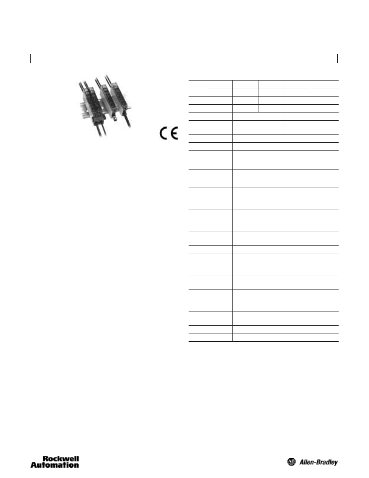
Product Description
The 45FSL is a DIN rail mountable fiber optic photoelectric
sensor with sophisticated part detection capabilities. Possible
modes of sensing include transmitted beam, diffuse and
retroreflective, allowing the 45FSL to be used in a variety of
complex applications.
Summary of 45FSL Features
S High-speed response—30µs
S High-intensity LEDs—penetrate dusty environments for
reliable detection of targets
S Dual LED indicators
S Output (orange), stability (green)
S Red or white source LEDs
S Selectable 40ms off delay output timer—“Pulse
stretcher” useful in high speed applications when the output
pulse must be lengthened to allow time for the machine
logic to respond.
S DIN rail mountable—for installation convenience, a steel
bracket is supplied for specific mounting requirements
S “Power-Bus” option—interface which allows user to
jumper power on several DIN rail mounted units to reduce
unnecessary wiring
S Cross-talk protection—prevents cross-talk between 4 or 8
sensors
S Short circuit, reverse polarity, false pulse and transient
noise protection
45FSL photoelectric sensors are designed for use with glass
or plastic fiber optic cables up to 2.2mm diameter. An adaptor
is supplied with the sensor for use with 1.25mm diameter
plastic fiber optic cables. No tools are required to attach or
remove fiber optic cables.
General Specifications
NPN Type
Model
PNP Type
Light Source Red LED White LED Red LED White LED
(Wave Length) (660nm) Ċ (660nm) Ċ
Response Time 250µs or 500µs 30µs
Current
Consumption
Power Supply 12 to 24V DC "10% Ripple 10% or less
Output Mode Open Collector
Stability Output Open Collector
Operation Mode Light on/dark on selectable
Output Timer Off delay/On delay selectable
Indicators Orange LED = Output, Green LED = Stability
Interference
Protection
Short Circuit
Protection
Features Power bus for easy wireless power distribution
Material Polycarbonate
Operating
Temperature
Operating Humidity 35% to 85% RH
Operating
Environment
Vibration 10-55Hz, 1mm amplitude, meets or exceeds
Approvals CE marked for all applicable directives
45FSL-2LGE 45FSL-5LGE 45FSL-2LVE 45FSL-5LVE
45FSL-2LHE 45FSL-5LHE 45FSL-2LWE 45FSL-5LWE
NPN: 35ma/PNP: 40ma 35ma max
Range Depends on Fiber
NPN Rated: 100ma @ 30V DC Max, <1V Residual
PNP Rated: 100ma @ 30V DC Max, <1V Residual
NPN Rated: 100ma @ 30V DC Max, <1V Residual
PNP Rated: 100ma @ 30V DC Max, <1V Residual
Delay time: 40ms fixed
Yes
Yes
Wiring Cable 2m (6.5ft) or pin pico QD connector or PB QD conĆ
nector
-25_C to +55_C (-13_F to 131_F)
NEMA 1, IP 40
IEC 60947-5-2
Shock 10g, 3 directions, 3 times
Accessories
S Mounting bracket: Quantity 1
S Instruction manual: Quantity 1
S Fiber adaptor: Quantity 1
Page 2
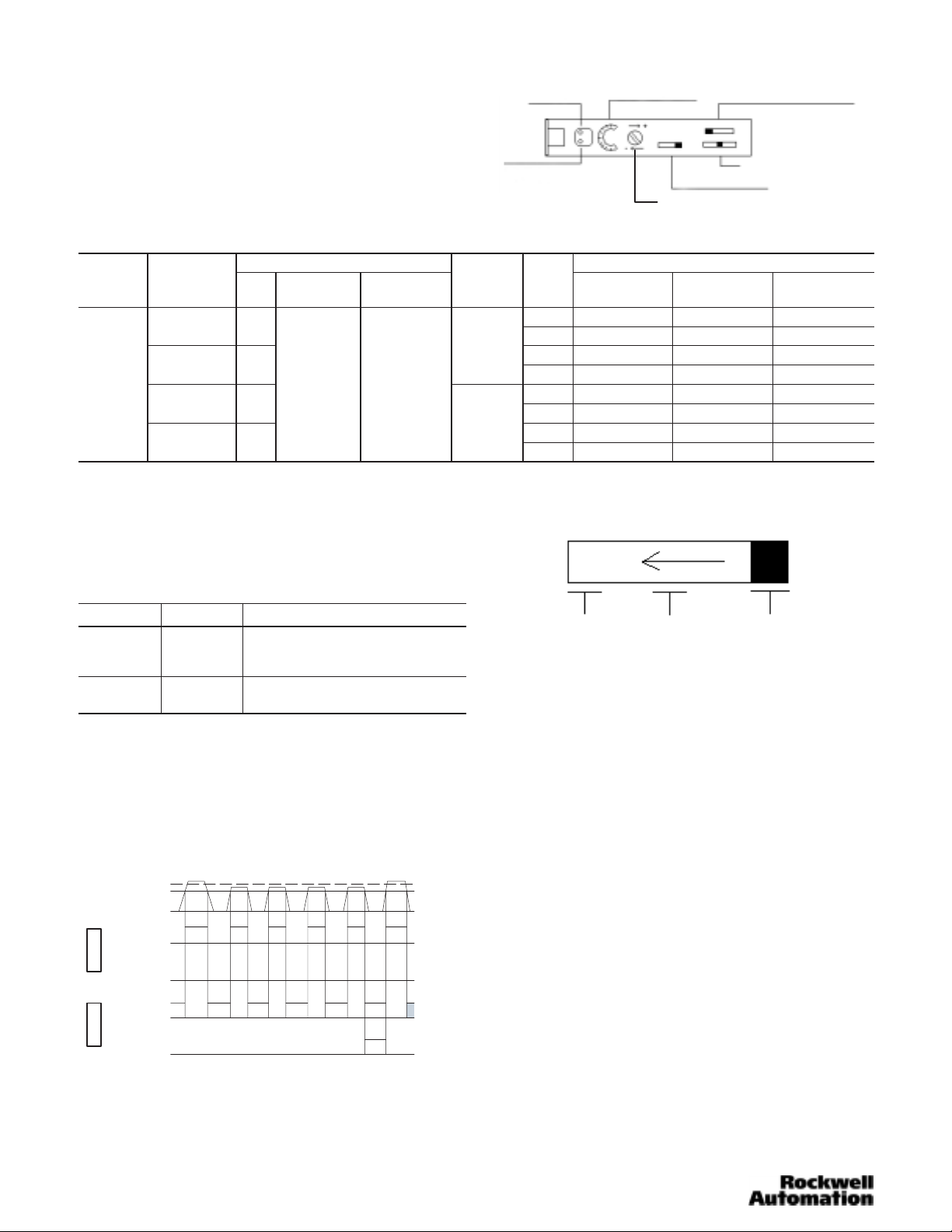
User Interface
Sel
250µs
12 24V DC
Output: 100ma
The user interface contains a light/dark operate switch, output
timer selector switch, interference protection switch, 8-turn
sensitivity adjustment knob with indication, and output LED
indicators for configuring and viewing the sensor’s operation
and status. A more complete description of each item is
described below.
Sensor Selection
Output Characteristics Catalog Number
Operating
Voltage
Current
Consumption
Type
Max Load
Current
40ma or Less PNP
12-24V DC
+/- 10%
35ma or Less NPN
Output: 100ma
Stability: 50ma
40ma or Less PNP
35ma or Less NPN
Ê PowerBus master/4 conductor QD = 45F–A4C–A2
PowerBus slave/2 conductor QD = 45F–A2C–A2
Max Leakage
Current
0.5ma
Response
Time
ectable
250µs
or
500µs
30µs
Stability Indicator
(Green LED)
Output Indicator
(Orange LED)
LED
Red
White
Red
White
Red
White
Red
White
8ĆTurn Sensitivity Indicator
8ĆTurn Sensitivity Adjustment
Interference Protection Selector Switch
Output Timer Selector Switch
Light/Dark Operate Switch
Cable Pico
45FSL-2LHE-A2 45FSL-2LHE-P4
45FSL-5LHE-A2 45FSL-5LHE-P4
45FSL-2LGE-A2 45FSL-2LGE-P4
45FSL-5LGE-A2 45FSL-5LGE-P4
45FSL-2LWE-A2 45FSL-2LWE-P4
45FSL-5LWE-A2 45FSL-5LWE-P4
45FSL-2LVE-A2 45FSL-2LVE-P4
45FSL-5LVE-A2 45FSL-5LVE-P4
Power Bus
(QD required)
45FSL-2LHE-C4 Ê
45FSL-5LHE-C4 Ê
45FSL-2LGE-C4 Ê
45FSL-5LGE-C4 Ê
45FSL-2LWE-C4 Ê
45FSL-5LWE-C4 Ê
45FSL-2LVE-C4 Ê
45FSL-5LVE-C4 Ê
Output and Stability Indicators
Two LEDs (green and orange) indicate a variety of conditions
to facilitate set-up and troubleshooting. The function of each is
described in the table below. Relevant output and stability
data are also shown.
LED State Condition
Green
ON
Flashing
OFF
Orange
OFF
ON
Stability Output is an output feature provided by the 45FSL
sensor which monitors any changes or reduction of reflected
light levels during operation. Reflected light levels must reach
120% of the threshold required for normal operation to
achieve a “Stability Output.” If the sensor detects light levels
less than 120% of threshold 4 consecutive times then the
green LED starts flashing and remains flashing until a stable
light level is achieved (120%) (see illustration below).
120%
100%
Operating Level
ON
Normal
Output
OFF
Light OnDark On
Stability
Output
Normal
Output
Stability
Output
ON
OFF
ON
OFF
ON
OFF
Unstable light signal
Stable light signal
4 consecutive unstable light levels
Output OFF
Output ON
Output Timer Selector Switch
OFF D ON D NOR
NOR: Provides normal on/off output switching
ON D: Provides output on delay (40ms)
OFF D: Provides output off delay (40ms)
8-Turn Sensitivity Adjustment
An 8-turn sensitivity adjustment (potentiometer) is built into the
sensor’s user interface for accuracy in detecting very small
objects or differentiating between colors.
Diffuse Set Up—Light Operate Mode
With target in position, turn sensitivity adjustment clockwise
until orange LED turns on (point A).
With no target in position the green and orange LEDs should
be off. Otherwise turn the sensitivity adjustment clockwise to
max or until orange LED turns on. If orange LED turns on,
then turn sensitivity adjustment counterclockwise until orange
LED turns off (point B).
Set sensitivity adjustment midway between points A and B.
Confirm sensor operation.
Transmitted Beam Set Up—Dark Operate Mode
With no target present, turn the sensitivity adjustment
clockwise to max until the orange and green LEDs turn on
(point A).
Green/orange LEDs should turn off. Otherwise turn sensitivity
adjustment counterclockwise until the green/orange LEDs turn
off. Turn sensitivity adjustment counterclockwise additional
one quarter turn and confirm sensor operation.
2
Page 3

Light/Dark Operate Switch
LIGHT or DARK operation modes may be chosen by
changing mode switch.
4/8 Channel Cross-Talk Protection
The 45FSL is equipped to prevent cross-talk to up to 4
ganged sensors providing a 250µs response time or up to 8
ganged sensors maintaining a 500µs response time. Each
sensor communicates through 2 small optic windows that
transmit and receive coded signals (see below).
Receiver
Transmitter
Side Mounting Sensor with Bracket
Fasten mounting bracket assembly
using M3 screws. Tightening torque is
0.8Nm max. Attach front hook of the
photoelectric sensor onto mounting
bracket and press rear end of sensor
down until unit snaps into place.
Ë
Ê
Wiring the Sensor
Choice of Power Bus, 2m (6.5ft) cable, or 4 pin QD connector
are provided for wiring the 45FSL Series sensors. On the pico
QD models Rockwell Automation/Allen-Bradley recommends
the use of the 889 Series cordsets and patchcords (i.e.,
889P–F4AB–2). Standard 2m (6.5ft) cable lengths are
provided with flying leads for hard wiring. Hard wiring color
coding and pin assignment for QD connectors are as specified
below.
Ganging up to 4 Sensors on DIN Rail
S Mount and align up to 4 sensors on DIN rail
S Move cross-talk selector switch to “4” on all sensors.
(Sensors will not function if cross-talk selector switch is set
to “8” on any sensor.)
S Install fiber optic cables
S Power up sensor
1
2
3
4
1
2
3
4
Ganging 4 to 8 Sensors on DIN Rail
S Mount and align up to 8 sensors on DIN rail.
S Move cross-talk selector switch to “8” on all sensors.
(Sensors will not function if cross-talk selector switch is set
to “4” on any sensor.)
S Install fiber optic cables
S Power up sensor
Lead Color
Designation
Termination
V+ Brown 1
0V Blue 3
Output Black 4
Stability Output Orange 2
2m (6.5ft) Cable
Pin Assignment
4 Pin Pico QD
2
143
The Power Bus option utilizes quick disconnect cordsets
which are prewired with up to four conductors. When ganging
sensors (up to 16 units maximum) using the Power Bus
connection system, select either a 4-wire cable (plus/minus
power output and stability output) or a 3-wire cable
(plus/minus power output) for the first control. For the
additional controls in a system, select either a 2-wire cable
(output and stability output) or a 1-wire cable (output only) to
complete the system.
Wiring Diagram/Power Bus Option
Maximum number of
units paralleled: 16
Mounting the Sensor
How to Attach Sensor to DIN Rail
Attach front hook of the photoelectric
sensor onto rail (or mounting bracket)
and press rear end of sensor down
until unit snaps into place.
How to Detach Sensor from DIN Rail
Pushing the sensor unit forward,
pull up on the front of the sensor
until the front hook is detached.
Remove sensor.
Female
End Cap
_
+
_
Male
+
End Cap
Ë
Ê
Black
Brown
+ V
- V
Blue
Orange
Stability
Black Output
Output
Orange
Stability
Black
Output
3
Page 4

Wiring Diagrams
Cable
NPN Output
PNP Output
Quick-Disconnect
NPN Output
PNP Output
Cable
Cable
1
4
3
1
2
4
3
Brown: 12V-24V DC
Black: Output
Blue: -DC
Orange: Stability
Brown: 12V-24V DC
Black: Output
Blue: -DC
Orange: Stability
Brown
Black
Orange2
Blue
Brown
Orange
Black
Blue
Load
Load
Load
Load
Dimensions
9
(0.35)
4 (0.16)
60 (2.36)
+
Receiver
-
Transmitter
+
-
Replacement Parts
5 (0.2)
(0.35)
30
(1.18)
3
(0.12)
9
4 (0.16)
4.7
(0.19)
21 (0.83)
11.5
(0.45)
2-3.2 (0.13)
Dia. hole
21 (0.83)
16
(0.63)
36.5 (1.44)
16
(0.63)
Mounting Bracket
2-3.2 (0.13) x 5.2
(0.2) oval hole
(0.12)
3
3
(0.12)
Cord
Bushing
4.8
(0.19)
Dia.
S Plastic Sensor Cover : PSC1
S Fiber Optic Cable (Diffuse) : 99–94
S Fiber Optic Cable (Transmitted Beam) : 99–90
+
-
+
-
S Pico QD Cordset : 889P–F4AB–2
S Power Bus QD Connectors:
2 Conductor = 45F–A2C–A2
4 Conductor = 45F–A4C–A2
S Power Bus End Caps:
Male Cap = 45F–AMC
Female Cap = 45F–AFC
PHOTOSWITCHR is a registered trademark
of Rockwell Automation.
Publication 75009–137–01(B)
May 2002
Printed in USA
4
 Loading...