

Page 1
Installation Instructions
IMPORTANT: SAVE THESE INSTRUCTIONS FOR FUTURE USE.
5.3
(0.209)
5.5
(0.217)
19.5
(0.768)
7
(0.28)
ø4.5
(0.177)
M12x1
41.5
(1.634)
2 x M4 4 (0.16)
15
(0.63)
10
(0.39)
7.5
(0.295)
49
(1.93)
2
(0.08)
22.5
(0.886)
A
B
57.5
(2.26)
17.5
(0.689)
65
(2.56)
A
B
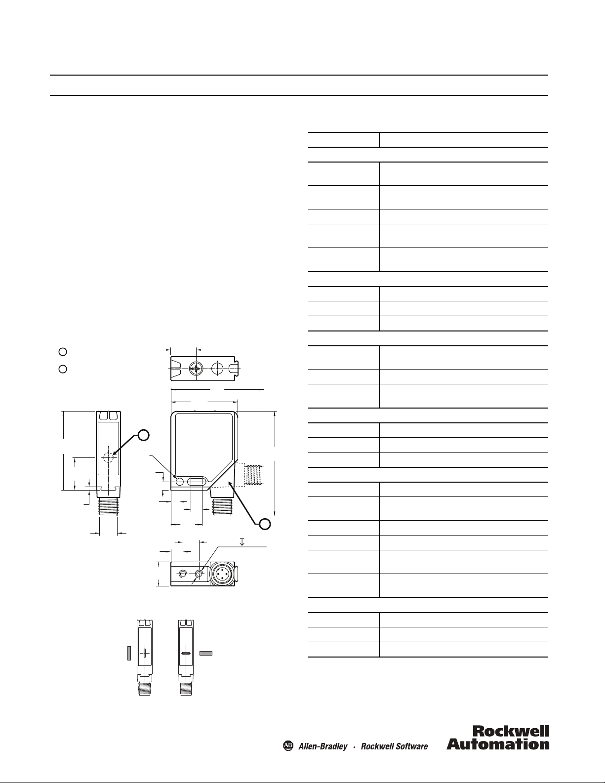
Optical axis
Connector, 90 ° adjustable
45CRM-4LHT1-D4
1 mm x 3 mm
(0.04 x 0.12)
45CRM-4LHT2-D4
3 mm x 1 mm
(0.12 x 0.04)
45CRM Color Registration Mark Sensor
Description
The 45CRM is a photoelectric contrast sensor that reliably
detects registration marks on a web. This sensor features red,
green, and blue (RGB) emitter LEDs. During the teach process
the sensor determines which of the emitter LEDs maximizes the
contrast between the registration mark and the web
(background). The teach process is completed using a simple
rotary switch.
The extremely fast response time enables the control system to
precisely align web material within the machine, for example,
lining up labels on a web with the cutting blade of the equipment
prior to the label being placed on a bottle.
Features
• Three emitter LEDs (red, green, and blue)
• 40
µ
s response time
• Three simple setup methods: dynamic teach, static teach or
IO-Link configurable
• Adjustable-position micro (M12) quick-disconnect (QD) for
mounting flexibility
Dimensions [mm (in.)]
Light spot orientation [mm (in.)]
Specifications
Certifications
Environmental
Operating
Environment
Operating
Temperature
Storage Temperature -40...75°C (-40...167° F)
Vibration
Shock
Optical
Sensing Ranges 11 mm ± 2 mm (0.43 ± 0.079 in.)
Angle Deviation max. ± 3°
Light Source 3 LEDs (red, green, blue)
Electrical
Voltage
Current Consumption ≤ 60 mA at 24V supply voltage
Sensor Protection
IO-Link
Protocol IO-Link V1.0
Interface Type IO-Link
Mode COM 2 (38.4 kBaud)
Outputs
Response Time 40 µs
Sensitivity
Adjustment
Output Type 2 x NPN/PNP complementary outputs
Output Mode Light or dark operation
Output Leakage
Current
Discrete Output
Rating
Mechanical
Housing Material Die-cast zinc, nickel-plated
Lens Material PMMA Luxacryl, clear
Connection Type Micro QD (M12), 4-pin, 90° adjustable position
cULus Listed and CE Marked for all applicable devices
IP67
-20...60°C (-4 ... 140° F)
10…55 Hz, 0.5 mm amplitude, meets or exceeds
IEC 60947-5-2
30 g with 11 ms pulse duration, meets or exceeds
IEC 60947-5-2
10...30V DC
when operating in IO-Link mode: 18 ... 30V
Short circuit, reverse polarity, and overload
protection
Rotary switch
≤ 100 µA per output
30V DC max./100 mA max.
Page 2
Power, Control and Information Solutions Headquarters
Americas: Rockwell Automation, 1201 South Second Street, Milwaukee, WI 53204-2496 USA, Tel: (1) 414.382.2000, Fax: (1) 414.382.4444
Europe/Middle East/Africa: Rockwell Automation NV, Pegasus Park, De Kleetlaan 12a, 1831 Diegem, Belgium, Tel: (32) 2 663 0600, Fax: (32) 2 663 0640
Asia Pacic: Rockwell Automation, Level 14, Core F, Cyberport 3, 100 Cyberport Road, Hong Kong, Tel: (852) 2887 4788, Fax: (852) 2508 1846
www.rockwel lautomation.com
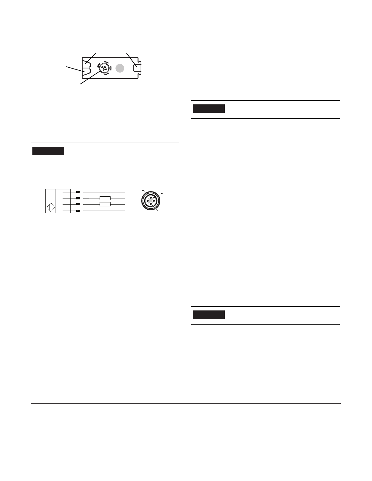
Controls and indicators
Yellow LEDs
Rotary Switch
Green LED
Operating
indicator
Signal indiaors
IMPORTANT
1
3
4
2
3
4
2
1
Blue
Black
White
Brown
+
LOAD
−
(Q2)
(Q1)
LOAD
NPN or PNP (Push-Pull)
IMPORTANT
IMPORTANT
TB
S
TD
TM
Mounting
Securely mount the sensor on a firm, stable surface or support for
reliable operation. A mounting subject to excessive vibration or
shifting may cause intermittent operation. A mounting bracket is
available for installation convenience. Once securely mounted,
the sensor can be wired per the wiring instructions in the next
section.
If the surface of the target object is shiny or
reflective, orient the sensor so it is angled at
approximately 10° to the surface.
Wiring
The 45LMS features complementary Push-Pull discrete outputs.
This means the outputs always drive either 24V or 0V and can
therefore be wired like either an NPN or a PNP sensor. For
example, when the sensor detects a registration mark, output Q1
will go to 24V and output Q2 will go to 0V. If the sensor is wired
for a PNP output, Q1 is ON when the sensor detects a mark and
Q2 is OFF. If wired for an NPN output, Q1 is OFF when the
sensor detects a mark and Q2 is ON.
The 45CRM photoelectric sensor is available with a micro QD
(M12) for ease of installation and maintenance.
Rockwell Automation recommends the use of the 889 Series of
cord sets and patch cords for quick-disconnect (QD) model
sensors. All external wiring should conform to the National
Electric Code and all applicable local codes.
Static Teach Mode
The static teach process is used to teach the sensor when the
web is not moving. It is sometimes required for more challenging
applications, as it allows for a more precise setup of the sensor.
The user teaches the registration mark color and the background
color separately. Either can be taught first. It is highly
recommended to teach both every time in order to achieve the
most reliable detection. However, it is not always necessary to
teach both. For example, you have to teach only the new mark
when the mark color changes but the background remains the
same.
When you change the Rotary Switch position, the
new mode takes effect after a 2-second delay. The
LEDs will not change state during this delay.
Teach Mark (TM)
Follow these steps to teach the mark:
1. Move the Rotary Switch to TM (The front Green and Yellow
LEDs will flash simultaneously indicating the sensor is ready to
be taught the mark.)
2. Place the mark in the light spot.
3. Move the Rotary Switch to S (or TB). The 45CRM learns the
color that is in the light spot when you move the Rotary Switch
away from TM.
4. Continue to the next section.
Teach Background (TB)
Follow these steps to teach the background:
1. Move the Rotary Switch to TB (The front Green and Yellow
LEDs will flash alternately, indicating the sensor is ready to be
taught the background.)
2. Place the background in the light spot.
3. Move the Rotary Switch to S for normal operation. The 45CRM
learns the color that is in the light spot when you move the
Rotary Switch away from TB.
Dynamic Teach Mode
The dynamic mode is used to teach the sensor while the web is
moving. The sensor automatically detects the background color
and the mark color as each passes through the sensor's
detection area (light spot). It selects the appropriate emitter LED
color and sets the threshold so that the primary output turns on
when the sensor detects a mark.
Sensitivity adjustment overview
When you change the Rotary Switch position, the
new mode takes effect after a 2-second delay. The
LEDs will not change state during this delay.
There are two simple teach methods for the 45CRM. The first
method is Static Teach, which is intended for applications where
the web can be stopped, or for more challenging applications.
The second method is Dynamic Teach, which is well suited for
applications where the web cannot be stopped for sensor
implementation.
Alarm feature: The 45CRM also has an alarm feature that alerts
the user via LEDs that the contrast taught is too low. The Green
and Yellow LEDs will flash at 8 Hz for approximately 7 seconds.
The sensor will revert to the last valid set-point for the mark and
the background.
10000237458 Ver 00 Copyright © 2012 Rockwell Automation, Inc. All Rights Reserved.
March 2012
Teach Dynamic (TD)
Follow these steps to teach using dynamic mode:
1. Move the Rotary Switch to TD.
2. Verify that at least one registration mark passes through the
light spot.
3. After a minimum of 2 seconds have elapsed, turn the Rotary
Switch to S for normal operation.
If the sensor does not display the Alarm Feature, then the
Dynamic Teach was successful.
 Loading...