

Page 1

Installation Instructions
IMPORTANT: SAVE THESE INSTRUCTIONS FOR FUTURE USE.
Bulletin 45CPD Analog Laser Sensor
Description
The 45CPD sensor is a Class 1 infrared laser sensor that provides
long distance sensing with both analog and discrete outputs. It is
set up using the Teach-In buttons on the top of the sensor and
can be programmed for several modes depending on the
application: object detection (single or dual output), object
position (analog output), object detection (background
suppression), or object detection (reflector mode).
This sensor utilizes the time of flight principle and has a relatively
small beam spot for applications typical for this sensing range (up
to 6 m). The sensor is completely self contained in an IP67
enclosure and does not require any external control devices
which add cost and require additional mounting space.
For convenience purposes, the 45CPD utilizes a visible red Class 2
laser for alignment purposes during the set up of the sensor in an
application. The Class 2 laser is automatically shut down when the
sensor is placed in normal operation and the Class 1 “eye safe”
laser is used.
The 45CPD can be easily set up by mounting the sensor such that
the target is within the operating range of the sensor, and
teaching in the appropriate set points required for the
application. The sensor can be set with any combination of 1 or 2
discrete PNP outputs and 4…20 mA analog output. The discrete
outputs can be set for Light Operate (L.O.) or Dark Operate (D.O.)
and the analog output is automatically scaled between the
taught set points with either a positive or negative slope.
The 45CPD is an excellent solution for long range detection and
measurement applications including: distance measurement,
verifying material position, stack level, thickness measurement,
roll diameter, web winding/unwinding, positioning fixtures, error
proofing, inspection, long standoff distance (hot or limited space),
level monitoring, and box width measurement.
Features
• Eye Safe Class 1 laser for operation
• Visible red Class 2 laser for set-up
• Six meter sensing range
• Two discrete outputs (PNP) and analog output (4…20 mA)
• Easy set-up using teach-in buttons
• IP67 enclosure
• Self-contained sensor
Specifications
Current Consumption 125 mA @ 24V DC
Supplied Accessories None
Optional Accessories Cordsets, mounting bracket
Operating Environment IP67
Operating Temperature
Sensing Beam Class 1 laser, IR 905 nm
Alignment Beam Visible red Class 2 laser, 650 nm
Spot Size 4 x 7 mm @ 2 m
(0.16 x 0.27 in. @ 6.56 ft)
4 x 12 mm @ 6 m
(0.16 x 0.47 in. @ 19.7 ft)
Sensing Range 0.20…6 m (0.7…19.78 ft)
Linearity 40 mm (1.57 in)
Repeatability Fast /slo w: 15 mm/10 mm
(0.6 in./0.4 in.)
Hysteresis 30 mm (1.2 in.) (fixed)
Tem pe ratu re Drift 1.2 mm/°C
Supply Voltage 18…30V DC
Circuitry Protection Short circuit, overload, false
pulse, transient noise, reverse
polarity protection
Output Type Two discrete PNP (L.O./D.O)
Analog Current 4…20 mA
Output Rating 100 mA max. for discrete outputs;
500 max. impedance for
analog output
Response Time Fast/slow: 13 ms/30 ms
Housing Material Plastic—ABS
Lens Material PMMA
LED Indicators Green: Power; Yellow: (2) Q
ouput; Orange: speed mode; Red:
(4) Teach-in indication
Connection Types 5-pin DC micro
Vibra tion 10…55 Hz, 1.5 mm amplitude; 3
planes; meets or exceeds IEC
60947-5-2
Shock 30 g; 11 ms; meets or exceeds
60947-5-2
C (F) -20…+60° (-4…140°)
Approvals UL, cULus and CE marked for all
applicable directives
A, QB
1
Page 2
This installation instruction should be read and understood
Operating Mode
Laser Class 1 (Infrared)
Set-up Mode
Laser Class 2 (Visible Red)
Do not stare into beam.
20
(0.78)
12.3
(0.48)
5.75
(0.226)
M12 x 1
94.39 (3.71)
81.5
(3.2)
93
(3.66)
42 (1.65) 43 (1.69)
42 (1.65)
(
)
(1) Brown
(4) Black
(2) White
(5) Grey
(3) Blue
18…30V
0V
Switch Output Q
A
Switch Output QB
Analog Output 4…20mA
Teach-In
Pad
Q
B
Output
(Yellow)
Speed Mode
(Orange)
Power
(Green)
Q
A
Output
(Yellow)
before operating the sensor.
The 45CPD sensor should only be installed by qualified personnel.
The 45CPD is not a safety component as described by the EU
machinery directives.
Mounting Bracket Dimensions—mm (inches)
45CPD –BKT1
45˚
R30
25 (0.98)
50 (1.96)
11 (0.43)
140.5 (5.53)
90.5 (3.56)
53 (2.08)
3.1 (0.12)
Dia.
R81.5
The 45CPD sensor is a Class 2 laser product. It utilizes a Class 2
visible red laser for alignment purposes during the set up. After
the sensor has been set up and is placed in the normal operation
mode, the Class 2 laser is shut down and a Class 1 Infrared laser
operates the device.
There is a natural eye aversion when looking into the laser beam
of a Class 2 laser. Do not look directly into the laser beam or
suppress the reflex to close your eyes.
The 45CPD should be mounted such that it is not directed at
people (head height) and the beam path is terminated at the end
of its functional path.
The laser safety label on the 45CPD sensor should be visible after
installation.
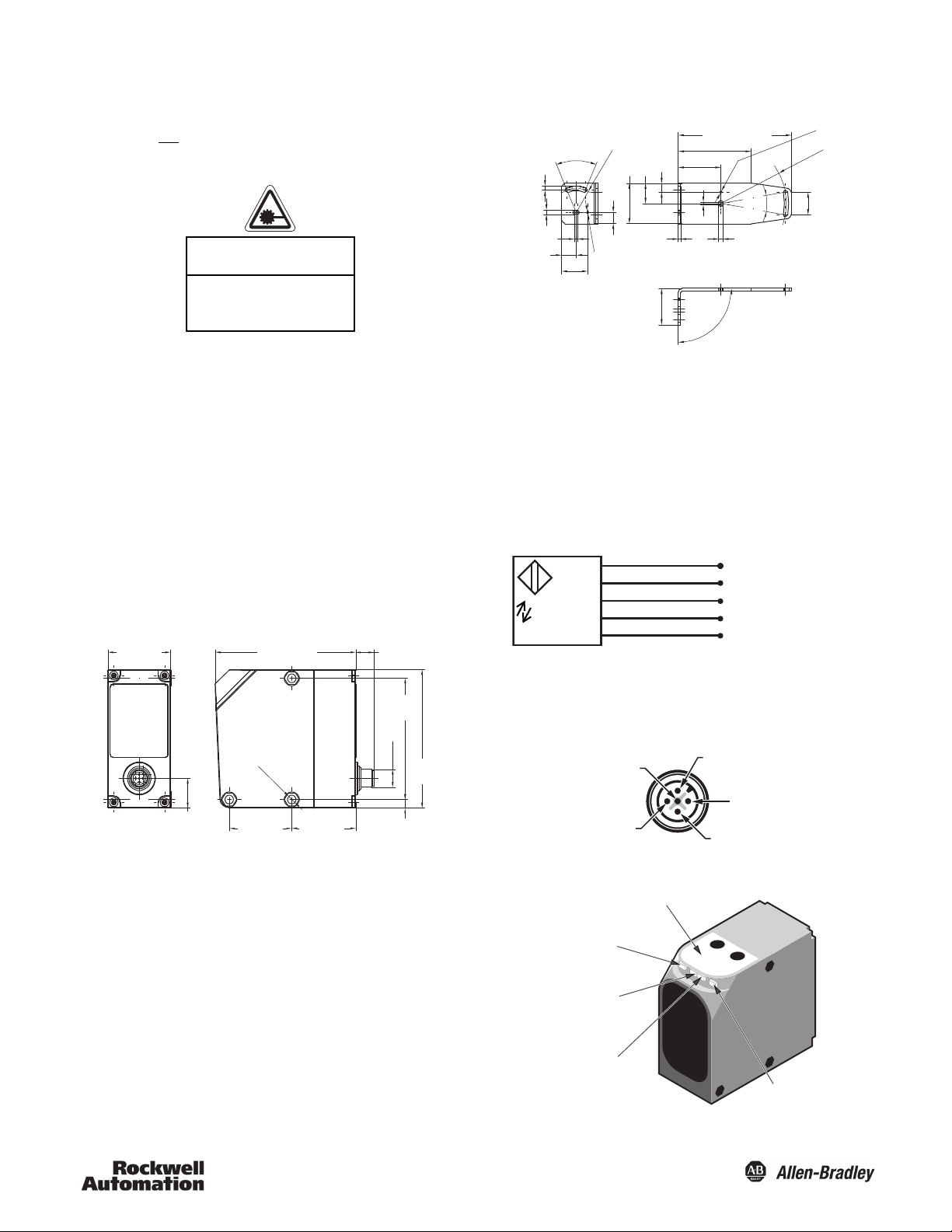
Dimensions—mm (inches)
5.2 (0.2)
5.2 (0.2)
4 (0.15)
18 (0.7)
32 (1.25)
14 (0.55)
3.1 (0.12)
Dia.
4 (0.15)
3
(0.11)
45
(1.77)
0.06
0.002
5.2 (0.2)
20˚
28
(1.1)
Wiring
The 45CPD photoelectric sensor is available with a micro quickdisconnect for ease of installation and maintenance. Rockwell
Automation recommends the use of the 889 Series of cordsets
and patchcords for quick disconnect model sensors. All external
wiring should conform to the National Electric Code and all
applicable local codes.
Wiring Diagram (45CPD-8LTB1-D5)*
Mounting
Securely mount the sensor on a firm, stable surface or support for
reliable operation. A mounting which is subjected to excessive
vibration or shifting may cause intermittent operation. The
45CPD-BKT1 mounting bracket is available for installation
convenience. Once securely mounted, the sensor can be wired
per the attached wiring diagram.
* For 45CPD-8LJB1-D5: (2) White = Analog output 4…20 mA and
(5) Grey = Switch output Q
B
Connection
5
3
2
1
4
Teach-In Pad and Indicators
2
Page 3

SPEED
Q
A
Q
B
As2
As1
PWR
0% analog
100% analog
INV.
SET
Bs2
Bs1
INV.
Allen-Bradley
Teach-In Buttons/Indicators
repeatability. Selection will depend on the requirements in the
application. The Speed mode is set by pressing the
button until
the Speed LED (Orange) is blinking fast. To select the slower speed
function press SET and the Speed LED will blink approximately
once per second. To select the higher speed function, press SET
and the Speed LED will blink approximately three times per
second. To teach the setting for either slow or fast speed, press
SET for approximately three seconds. The four teach-in indicators
will blink three times when complete. When the sensor is put in
Slow mode has a slower switching frequency with higher
The SET button sets the function that is currently indicated by the
Teach-In LEDs. To SET, press button for approximately three seconds
until LED blinks three times.
The button advances to the next function. After advancing
through the entire menu, it will begin at the first function.
Teach-In Indicators
AS1 AS2 BS1 BS2 Speed
Turn on switchpoint for QA X
Turn off switchpoint for QA X
Invert Output for QA (L.O./
D.O.)
Turn on switchpoint for QB X
Turn off switchpoint for QB X
Invert Output for QB (L.O./
D.O.)
0% point for Analog
Output
100% point for Analog
Output
Speed Mode X
XX
XX
XX
XX
The discrete and analog output functions can be set in
combination (e.g., two discrete outputs and the analog output).
General Set Up
The 45CPD is set up using the pushbuttons (SET and
) and the
LED indicators on the top of the sensor.
To begin the Teach-In process, Press the SET button for three
seconds.
This will automatically turn on the visible red alignment laser.
Scrolling through the Teach-In functions is done using the
button. After the last function is reached the menu is started
again from the first function.
To teach the selected function indicated by the teach-in LEDs as
shown in table above, press SET for approximately three seconds.
The LED will blink three times when complete.
After the desired functions are set, press SET and
simultaneously for approximately one second to exit the Teach-In
mode. The sensor will begin normal operation based on the
Teach-In settings. The visible red Class 2 laser will turn off and the
infrared Class 1 laser will turn on.
(Note: To reset the sensor to the factory setting, sensor should be
in the operating mode. Press the
button for approximately 15
operation, the LED will be turned on when running in the Slow
mode.)
Modes of Operation for Typical Applications:
Object Detection—Single Output
To set the output for Q
AS1 LED and a switch off point indicated by the AS2 LED.
Q
Output
A
Once in the Teach-In mode press the
Position the target at the desired switch on point and then press
the SET button.
(If the target is not within the measuring range or cannot be
detected the AS1 LED will blink.)
Press the button to advance to the AS2 function which is
indicated by the teach-in LED.
Position the target at the desired switch off point and then press
the SET button.
If desired, the output can be inverted for this switching window
(L.O./D.O. function). Press until both the AS1 and AS2 LEDs are
turned ON and then press the SET button. This is also indicated
by the “INV” text on the teach-in pad.
After this Q
A setting has been completed, press SET and
simultaneously for approximately one second to begin normal
operation.
Object Detection—Dual Output
To set the output for both Q
procedure as the Q
additionally teach the QB output using the BS1 and BS2 LEDs.
A there is a switch-on point indicated by the
A
S1
until the AS1 LED turns ON.
A and QB, follow the same teach-in
A Single Output (shown above) and
A
S2
seconds until the menu LEDs turn on briefly.)
(Note: The Speed Mode of the 45CPD can be adjusted for either a
Fast or Slow mode of operation. The Fast mode enables faster
switching speeds which have a slightly lower repeatability. The
3
Page 4

Object Position—Analog Output (4 to 20mA)
Q
B
Output
B
S2
B
S1
Q
A
Output
A
S2
A
S1
AS1 & BS1
0%
AS2 & BS2
100%
Analog Output
Analog Current (mA)
20
4
Background
Target Used
as Reflector
A
S2
A
S1
Once in the Teach-In mode press the button and advance until
both the A
S1 and BS1 function LEDs are turned on. This is also
indicated by “0% analog” on the teach-in pad.
Position the target at the desired 0% position (4 mA) and then
press the SET button.
(If the target is not within the measuring range or cannot be
detected both AS1 and BS1 LEDs will blink.)
Press the button and advance until both the AS2 and BS2
function LEDs are turned on. This is also indicated by “100%”
analog on the teach-in pad.
Position the target at the desired 100% position (20 mA) and then
press the SET button.
The 4…20 mA analog output is automatically scaled between the
0% and 100% positions which have been set.
shown in the diagram below (creates a larger switching window).
Background targets will be suppressed beyond the A
S2 switch
point.
Background
Is Suppressed
A
S2
QA Output
A
S1
Object Detection—Reflector Mode Using a Background
Object as the Reflector
To set the output for Q
procedure as in the single output
A in the reflector mode, follow the same
mode above. Set the AS1 and AS2
switch points such that the background “reflector” will be
approximately midway between them as shown in the figure
below. The background object can be a floor, wall, conveyor, etc.
The output can be set up for Light Operate or Dark Operate by
inverting the output. Press
until both the AS1 and AS2 LEDs are
turned ON and then press the SET button. This is also indicated
by “INV” on the teach-in pad.
After the settings have been completed successfully, press SET
and
simultaneously for approximately one second to begin
normal operation.
(Note: The minimum measuring range for the analog output is
600 mm. If the setpoints are less than 600 mm apart, the sensor
will automatically scale the analog output (0…100%) to 600 mm
and the midpoint of this will be automatically set at the midpoint
between the two original setpoints.)
(Note: To invert the slope, the 0% position and 100% position
settings will need to be reversed and reset. The 0% setting is the
“close” setting for a positive slope. For a negative slope the 0%
setting should be the “far” setting.)
Object Detection—Background Suppression
To set the output for Q
follow the same procedure as in the single output
except move the switch on point
A in a background suppression mode,
(AS1) closer to the sensor as
mode above,
Application Notes
1. The sensor should be powered for approximately five minutes
for maximum precision.
Accessories
Description Cat. No.
2 m (6.5 ft) micro DC cordset 889D-F5AC-2
Mounting Bracket 45CPD-BKT1
Publication 75009-268-01(C)
[068-13807]
April 2008
4
 Loading...