

Page 1
1
Installation Instructions
45CLR ColorSight™
(3 Output Channel Color Sensor)
IMPORTANT: SAVE THESE INSTRUCTIONS FOR FUTURE USE.
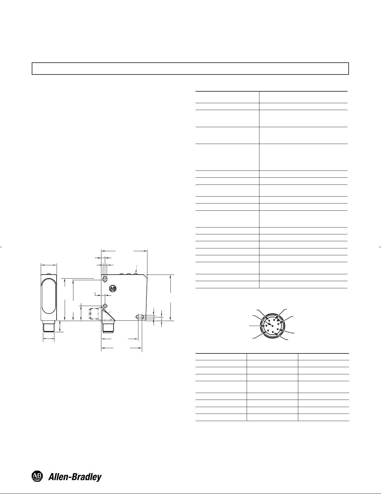
Approximate Dimensions [mm (inches)]
50 (1.97)
50
(1.97)
40 (1.57)
44 (1.73)
16 (0.63)
13.5 (0.53)
46
(1.81)
44
(1.73)
17
(0.67)
4.3
(0.17)
4 (0.16)
4 (0.16)
4.3 (0.17)
4 (0.16)
M12 x 1
Allen-Bradley
Features
Description
General Specifications
Pinout and Color Codes
Pin Color Connection
1 White Gate Input
2 Brown V+ 12…28V DC
3 Green OUT 1
4 Yellow
OUT 2/Teach
Confirmation
5 Grey Teach Button Lock
6 Pink OUT 3/Remote Teach
7 Blue V- 0V DC
8 Red Not Connected
The ColorSight™ 45CLR is a self-contained color detection sensor
with three PNP output channels. This sensor utilizes a single white
LED light source with three available spot size models for full color
spectrum detection and maximum application flexibility.
The 45CLR ColorSight can be set up to detect:
y A single color per channel with adjustable tolerance
y Scan an area of various colors on the same surface
y Detect multiple individual colors per channel
y Wide sensing range tolerance
y Three channel color matching (three outputs)
y Gating input (Also known as inhibiting input)
y Adjustable tolerance for high precision to general color matching
y Optional pulse stretching (50 ms)
y Teach colors via pushbuttons
y External teach capability
y Teach button lockout
y 270° rotatable connector
y IP 67 enclosure
Certifications
cULus and CE marked for all applicable
directives
Light Source White LED
Sensing Range [mm (in.)]
45CLR-5JPC1-D8: 12…32 (0.47…1.26)
45CLR-5JPC2-D8: 15…30 (0.59…1.18)
45CLR-5JPC3-D8: 18…22 (0.70…0.86)
Sensing Range Tolerance
45CLR-5JPC1-D8: ± 6 mm
45CLR-5JPC2-D8: ± 5 mm
45CLR-5JPC3-D8: ± 2 mm
Spot Size [mm (in.)]
45CLR-5JPC1-D8:
4 (0.15) round @ 22 (0.86)
45CLR-5JPC2-D8:
2 x 2 (0.07 x 0.07) @ 22 (0.86)
45CLR-5JPC3-D8: 5 x 1 (0.19) @ 22 (0.86)
Supply Voltage 18…28V DC
Current Consumption
≤40 mA @ 24V DC
Protection Type
Short circuit, overload, false pulse,
transient noise, reverse polarity
Output Type Discrete: 3 PNP outputs (N.O.)
Output Rating 100 mA max per channel output
Response Time
Output: Normal Teach mode
(CH1,CH2,CH3): 1 mS
External Teach mode (CH3): 2 mS
Housing Material Plastic ABS
Lens Material PMMA
Connection Type 8-Pin DC Micro, 270° Rotatable
Accessory Cordsets, Mounting Brackets
Enclosure Type Rating IP67
Vibration
10…55 Hz, 1.5 mm amplitude; 3 planes;
meets or exceeds IEC 60947-5-2
Shock 30 g; 11 ms; meets or exceeds 60947-5-2
Operating Temperature—C (F) -10…+55° (14…131°)
5 GY
6 PK
7 BU
8 RD
4 YE
3 GN
1 WH
2 BN
M12 Male
Page 2
2
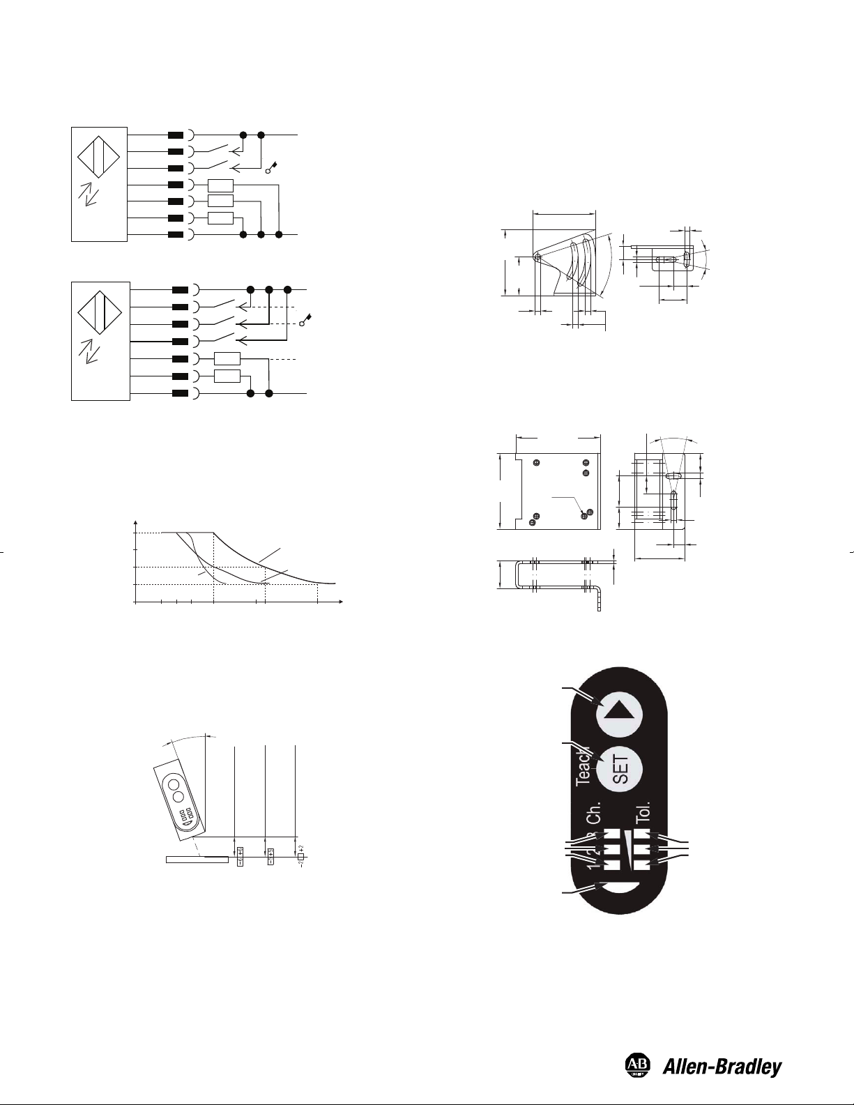
Mounting
Securely mount the sensor on a firm, stable surface or support for
reliable operation. The following mounting brackets are available for
installation convenience and sensor protection. Once securely
mounted, the sensor can be wired per the attached wiring diagrams.
45BPD-BKT1 Approximate Dimensions—mm (in)
Wiring Diagrams
48.5 (1.9)
4.3 (0.169)
4.2
(0.165)
10.5 (0.41)
22 (0.86)
24˚
4.3 (0.169)
10.5
(0.41)
50˚
30
(1.18)
50.97
(2.0)
4.3
(0.169)
2
(0.07)
21.2
(0.83)
13.9
(0.54)
58
(2.28)
4.3
(0.169)
24˚
4.3 (0.169)
14.85 (0.58)
17
(0.66)
23.8
(0.93)
7 x M4
38.2 (1.5)
8.5
(0.33)
65 (2.55)
45BPD-BKT2 (Protective Bracket) Approximate
Dimensions—mm (in)
Teach Interface
Red Tolerance LEDs
► Button
SET Button
Yellow Output Channel LEDs
Green Indicator LED
Remote Teach
+DC
Gnd
2
1
5
6
4
3
7
Gating Input
Q1
Remote Teach
Teach Lock
GY
BN
WH
PK
YE
GN
BU
Teach Confirmation
The control input (pin 5) can be used to lock the ColorSight
pushbuttons by connecting it to the +DC (18…28V DC). When
working with the sensor in remote teach, we recommend the use of
pushbutton lockout to prevent accidental tampering of the
configuration.
Percentage of Color Detection vs. Sensing Range
Sensor Alignment
Position the 45CLR sensor so that the distance from the object to
the sensor will be within the sensing range. Extremely shiny or
reflective surfaces can distort the color detection This sensor should
be mounted at an angle of 10...30°, as shown below.
45CLR-5JPC1-D8
15
30
18
> 20 % Reflective
mm
25
50
75
100
12 22 32 42
%
45CLR-5JPC2-D8
45CLR-5JPC3-D8
12…32 mm 45CLR-5JPC1-D8
10…30°
15…30 mm 45CLR-5JPC2-D8
18…22 mm 45CLR-5JPC3-D8
2
1
5
6
+DC
Gnd
GY
BN
WH
PK
YE
GN
BU
4
3
7
Q3
Q2
Q1
Teach Loc
k
Page 3

3
Gating Input: High (+DC)
(Outputs inactive, light source off)
Low (0V) or float/not connected
(Sensor active)
Tolerance Levels
After an object has been taught, move the object manually within
the sensing range or positions that can occur in your application.
Check that the programmed channel is effectively detecting the
color. If the color is not being detected reliably adjust the tolerance
one level higher. By repeating this procedure, the optimal tolerance
level can be determined.
Adjusting the tolerance levels on the 45CLR enables the user to
define the amount of variation in color that the sensor will detect.
For example, a tight tolerance will only detect the specific color
taught to the sensor while a wide tolerance can detect slightly
lighter or darker shades of the color. Up to five tolerance levels can
be selected as shown on the chart below.
Gating Input
Target
GT
Ch X
H
L
H
L
H
L
1. Place the color target within the sensing range.
2. Enter teach mode by pressing SET for three seconds until the
green LED turns off and the yellow channel one LED turns on.
Note that the white light turns off when you enter teach mode.
3. Push SET for three seconds until the tolerance LED (red) turns
on. Press X to adjust tolerance to the desired level. When
changing the tolerance levels, the green LED works as a guide
indicating if the color tolerance is too low for detection as
described in the Tolerance Levels section above.
4.
Push for three seconds to confirm the desired tolerance level.
5.
The sensor is now ready to operate (yellow channel one LED is
on when the target is present). White LED detection beam is also
on during normal operation.
1.
Place the object with various colors within sensing range.
2. Enter teach mode by pressing SET for three seconds until the
green LED turns off and the channel one yellow LED turns on.
Note that the white LED light spot is also turns off.
3.
Select the channel you want to teach using the X button.
4. Press and hold SET until the green LED is blinking. Continue to
hold SET while moving the object to scan all colors by the
sensor’s white light spot. When you are finished scanning the
object, release the SET button.
Normal Teach
To teach the sensor to learn multiple colors using multiple channels:
1. Place the color target within the sensing range.
2. Enter teach mode by pressing SET for three seconds until the
green LED turns off and the yellow channel one LED turns on.
3.
Select the desired channel to teach using the X button. To
confirm the color to be taught for a selected channel Press SET
for three seconds until the red tolerance LED turns on.
4. Select desired tolerance level. When changing the tolerance
levels, the green LED works a guide indicating if the color
tolerance is too low for detection.
5. Press SET for three seconds until the red tolerance LED turns off
to exit teach mode.
123
Tolerance
Tol.
Tol.
Tol.
Tol.
Tol.
1
2
3
4
5
(tight)
(medium)
(wide)
Repeat instructions to teach additional channels.
Advanced Teach (Color Scan)
The Color Scan feature enables you to teach and detect objects
with various colors and individual multiple colors to each channel.
5. The sensor is now ready to operate. (Confirm that the scanned
objects turn the channel yellow LED on.)
Repeat instructions to teach additional output channels.
The Gating Input can be used to inhibit the operation and output of
the 45CLR. This allows the user to only operate the 45CLR when
another sensor detects that the object is present. For example, the
”gating” sensor detects when a bottle is present, and only at that
time the 45CLR detects the color of the cap.
45CLR ColorSight Setup
The 45CLR ColorSight is set up using the pushbuttons (SET and X)
and the LED indicators on the top of the sensor. There are three
available ways to set up the sensor:
Simple Teach
To teach the 45CLR ColorSight to detect a single color using one
channel:
To teach multiple individual colors per channel
The Color Scan feature can be used to teach multiple individual
colors per channel using the same procedure as above. In step 4,
present individual colors in a sequential (without any disruptions)
manner.
Page 4

4
Special Functions
Remote Teach
1. Enter teach mode by pressing SET for three seconds until the
green LED turns off and the yellow channel one LED turns on.
2.
Press X until all three yellow channel (CH1, CH2, CH3) LEDs turn
on.
3. Press SET for three seconds to confirm.
4.
Press X until the middle red tolerance LED is on.
5. Press SET for three seconds to confirm.
6.
Press X until all the red (tolerance) LEDs turn off.
7. Press SET for three seconds.
8. The sensor is now in Remote Teach mode. When entering remote
teach mode the output Q3 becomes a teach input. Connect this
pin to +V/+DC to teach a new color with medium tolerance on
channel one. In Remote Teach mode, output Q2 is a teach
acknowledgment. When the sensor is successfully taught a color,
output Q2 will turn on for 50 mS to confirm a successful teach.
Tol.
Tol.
Pulse Stretching
1. Enter teach mode by pressing SET for three seconds until the
green LED turns off and the channel one yellow LED turns on.
2.
Press X until all three yellow channel (CH1, CH2, CH3) LEDs turn
on.
3. Press SET for three seconds to confirm.
4.
Press X until the red low tolerance LED turns on.
5. Press SET for three seconds to confirm.
6.
Press X until all the red (tolerance) LEDs turn off.
7. Press SET for three seconds.
8. The sensor is now ready to operate. (Yellow channel LED is on
when target is present.) A color match on any channel will result
in an output signal at least 50 mS in length.
Default Factory Settings
To configure the sensor to the manufacturer's default settings:
1. Enter teach mode by pressing SET for three seconds until the
green LED turns off and the channel one yellow LED turns on.
2.
Press X until all three yellow channel (CH1, CH2, CH3) LEDs turn
on.
3. Press SET for three seconds to confirm.
4.
Press X until the (CH1 & CH2) red tolerance LED turns on.
5. Press SET for three seconds to confirm until the green power
LED turns on.
6.
Press X until all the red (tolerance) LEDs turn off.
7. Press SET for three seconds until the green power LED turns on.
The sensor has now been set to manufacturer's default settings.
All special functions are de-activated and previous color settings
are reset.
Tol.
Tol.
Cordsets and Accessories
Publication: 10000007742
[068-14169]
January 2008
Printed in USA
Description
Cat. No.
DC Micro Style QD Cordset, 8-Pin
889D-F8AB-2
Mounting Bracket. Used for Laser Sensors
45CPD, 45BRD
45BPD-BKT1
Protective Mounting Bracket. Used for
Laser Sensors 45CPD, 45BRD
45BPD-BKT2
 Loading...