

Page 1
Guardmaster® 440C-CR30
Software Configurable Safety Relay
Quick Start Guide
Page 2
Important User Information
IMPORTANT
Solid-state equipment has operational characteristics differing from those of electromechanical equipment.
Safety Guidelines for the Application, Installation and Maintenance of Solid State Controls (publication
SGI-IN001_-EN-P
http://www.rockwellautomation.com/literature/
equipment and hard-wired electromechanical devices. Because of this difference, and also because of the wide
variety of uses for solid-state equipment, all persons responsible for applying this equipment must satisfy
themselves that each intended application of this equipment is acceptable.
In no event will Rockwell Automation, Inc. be responsible or liable for indirect or consequential damages
resulting from the use or application of this equipment.
The examples and diagrams in this manual are included solely for illustrative purposes. Because of the many
variables and requirements associated with any particular installation, Rockwell Automation, Inc. cannot
assume responsibility or liability for actual use based on the examples and diagrams.
No patent liability is assumed by Rockwell Automation, Inc. with respect to use of information, circuits,
equipment, or software described in this manual.
Reproduction of the contents of this manual, in whole or in part, without written permission of Rockwell
Automation, Inc., is prohibited.
available from your local Rockwell Automation sales office or online at
) describes some important differences between solid-state
Throughout this manual, when necessary, we use notes to make you aware of safety considerations.
WARNING: Identifies information about practices or circumstances that can cause an explosion in a hazardous environment,
which may lead to personal injury or death, property damage, or economic loss.
ATTENTION: Identifies information about practices or circumstances that can lead to personal injury or death, property
damage, or economic loss. Attentions help you identify a hazard, avoid a hazard, and recognize the consequence.
SHOCK HAZARD: Labels may be on or inside the equipment, for example, a drive or motor, to alert people that dangerous
voltage may be present.
BURN HAZARD: Labels may be on or inside the equipment, for example, a drive or motor, to alert people that surfaces may
reach dangerous temperatures.
Identifies information that is critical for successful application and understanding of the product.
It is recommended that you save this user manual for future use.
Rockwell Automation Publication 440C-QS001A-EN-P — January 2014
Page 3

Quick Start Guide
Table of Contents
Introduction . . . . . . . . . . . . . . . . . . . . . . . . . . . . . . . . . . . . . . . . . . . . . . . . . . . . . . . . . . 1
Assumption . . . . . . . . . . . . . . . . . . . . . . . . . . . . . . . . . . . . . . . . . . . . . . . . . . . . . . . . . . 1
Schematic/Setup . . . . . . . . . . . . . . . . . . . . . . . . . . . . . . . . . . . . . . . . . . . . . . . . . . . . . 1
Configuring the Guardmaster 440C-CR30. . . . . . . . . . . . . . . . . . . . . . . . . . . . . . 2
Configuring the PanelView 600. . . . . . . . . . . . . . . . . . . . . . . . . . . . . . . . . . . . . . .16
Verify Operation . . . . . . . . . . . . . . . . . . . . . . . . . . . . . . . . . . . . . . . . . . . . . . . . . . . . . 24
Fault and Status Reporting . . . . . . . . . . . . . . . . . . . . . . . . . . . . . . . . . . . . . . . . . . .28
Introduction
Safety systems are often described as a safety function that consists of inputs
devices, a logic device and output devices. In this example application, we have
two safety input devices: a SensaGuard interlock that monitors a safety gate and
an e-stop push button that is located in a readily accessible area. Our logic
device is a Guardmaster 440C-CR30 software configurable safety relay. We have
two safety rated output devices, both of which are 700HPS-2Z24 relays with
positive opening contacts. The Guardmaster 440C-CR30 monitors the 700HPS
output devices through the plug-in module. Opening the gate or pressing the
e-stop causes the 700HPS relays to turn off, which disconnects the power to the
hazards before the operator can reach the hazard.
Our next consideration is returning power to the machine. In our example
application, the operator opens the gate and walks into the hazard area. In such
cases, a manual reset of the safety system is required. The reset signal is not a
safety signal and therefore can be provided by a graphical display.
Assumptions
1. The user has loaded CCW Version 6.0 (or later) onto their computer.
2. The user has setup an Ethernet connection to the PanelView.
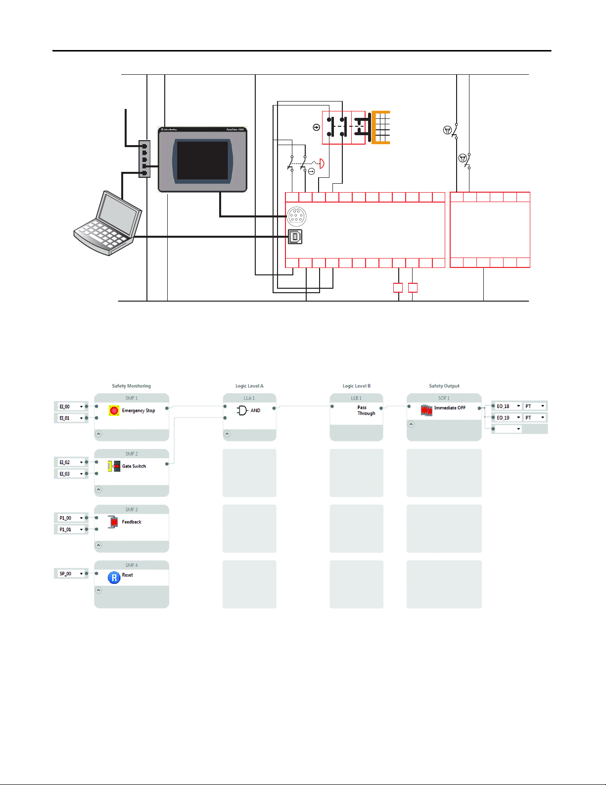
Schematic/Setup
The schematic of our example safety system is shown below.
a. A PanelView C600 has a serial connection to the Guardmaster 440C-
CR30.
b. The PC has a USB connection to the Guardmaster 440C-CR30 and an
Ethernet connection to the PanelView C600.
c. An e-stop is connected to Inputs 00 and 01 and the e-stop uses test
pulses A and B from terminals 12 and 13.
d. A Trojan T15 GD2 tongue interlock monitors a safety gate. It also uses
test pulses A and B from terminals 12 and 13.
e. Two 700HPS relays are connected to output terminals 18 and 19.
f. The normally closed outputs of the 700HPS are connected to terminals
I-00 and I-01 of the Plug-in Module.
g. The reset signal is provided by the PanelView C600.
Rockwell Automation Publication 440C-QS001A-EN-P — January 2014 1
Page 4
Quick Start Guide
05
440C-CR30-22BBB
02
0100
03
04
A1 15 20 21
700HPS-XZ24 Relay
700HN-123 Base
160618A2
071908 10 11
K1
K2
12 13 14
09
17
2080-IQ4OB4
COM
I-01I-00
+24
O-00 O-01
COM
I-03I-02
-24
O-02 O-03
1761-CBL-PM02
USB Cable
Male A to Male B
To Ethernet
Network
PanelView C600
2711C-T6T
Modbus Master
Stratix 2000
1783-US05T
Unmanaged
Ethernet Switch
Personal
Computer
+24V DC
24V Com
AB
21
3
4
687
5
K2
K1
Trojan T15 GD2
440K-T11463
Configuring the Guardmaster 440C-CR30
In this section, we will configure the Guardmaster 440C-CR30 workspace to
match the schematic.
2 Rockwell Automation Publication 440C-QS001A-EN-P — January 2014
Page 5

Quick Start Guide
1. Start the CCW. Click on the Windows Start button and then click on the
Connected Components Workbench.
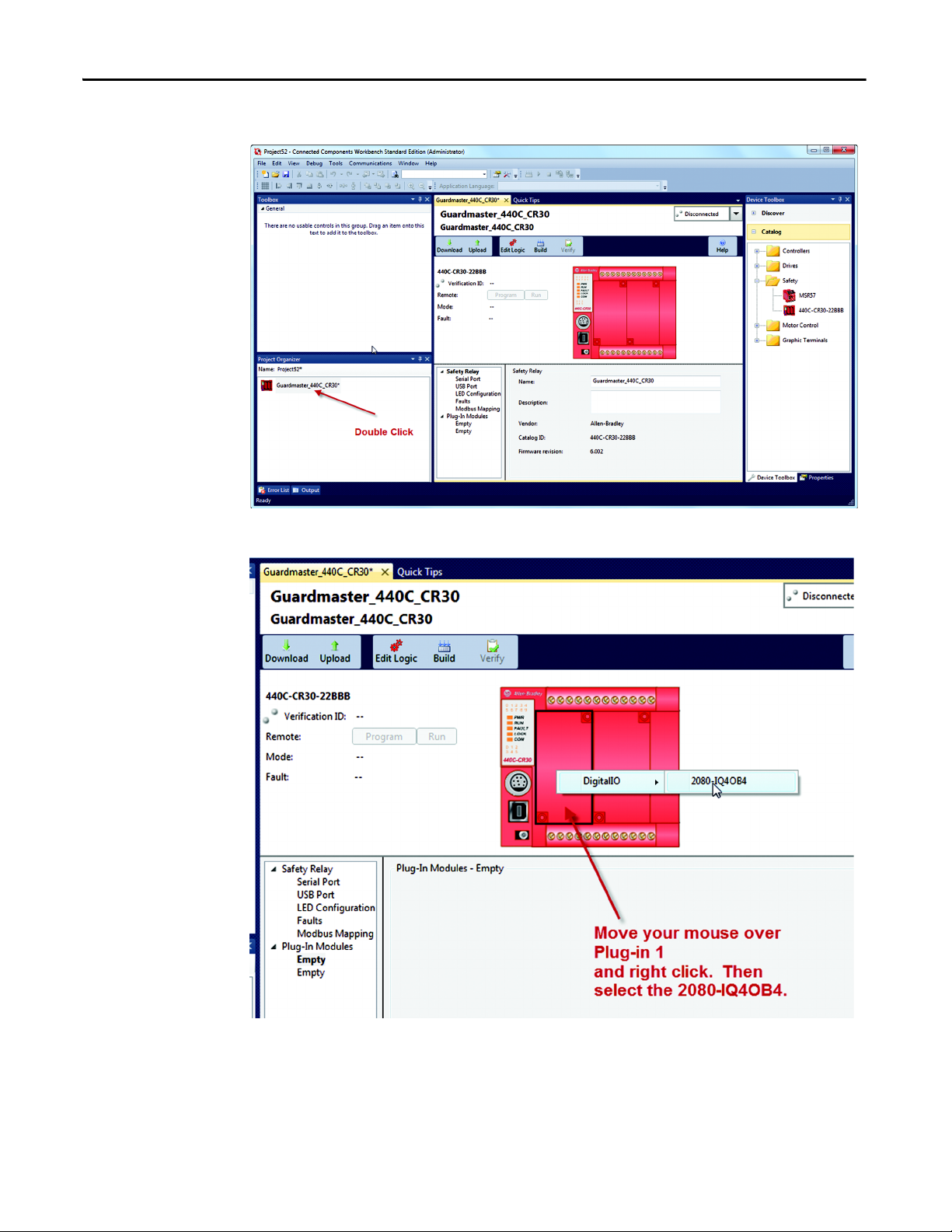
2. Expand the catalog items. Double click on the 440C-Guardmaster
440C-CR30-22BBB to load it into the Project Organizer.
Rockwell Automation Publication 440C-QS001A-EN-P — January 2014 3
Page 6
Quick Start Guide
3. Double click on the controller.
4. Load the Plug-in Module
4 Rockwell Automation Publication 440C-QS001A-EN-P — January 2014
Page 7
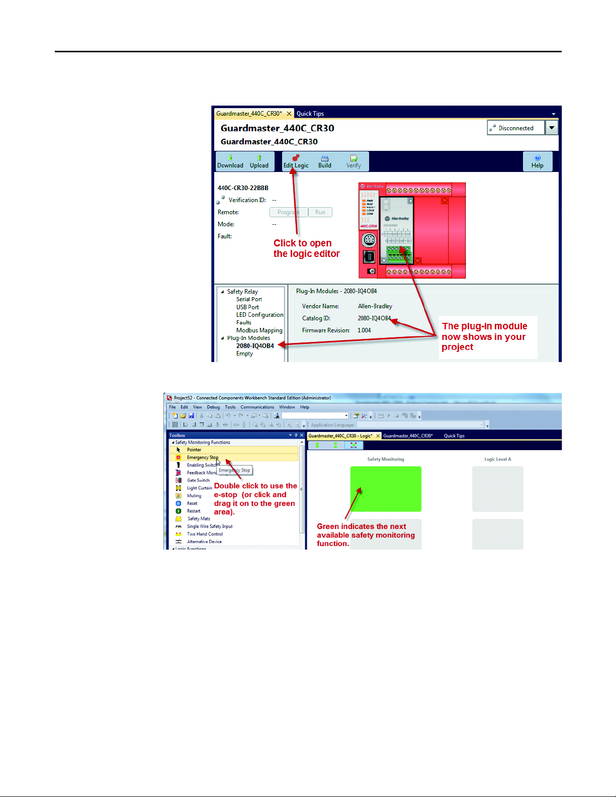
Quick Start Guide
5. Open the Logic Editor. Also note that the Digital Input Module shows in the
project.
6. Load the e-stop.
Rockwell Automation Publication 440C-QS001A-EN-P — January 2014 5
Page 8
Quick Start Guide
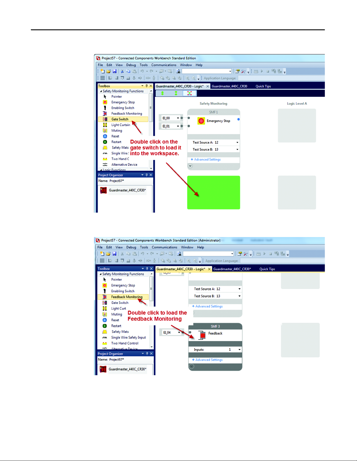
7. Load the Gate Switch.
8. Load the Feedback monitoring. (Use the vertical scroll bar to adjust the
workspace up to see the next available safety monitoring spot.)
6 Rockwell Automation Publication 440C-QS001A-EN-P — January 2014
Page 9
Quick Start Guide
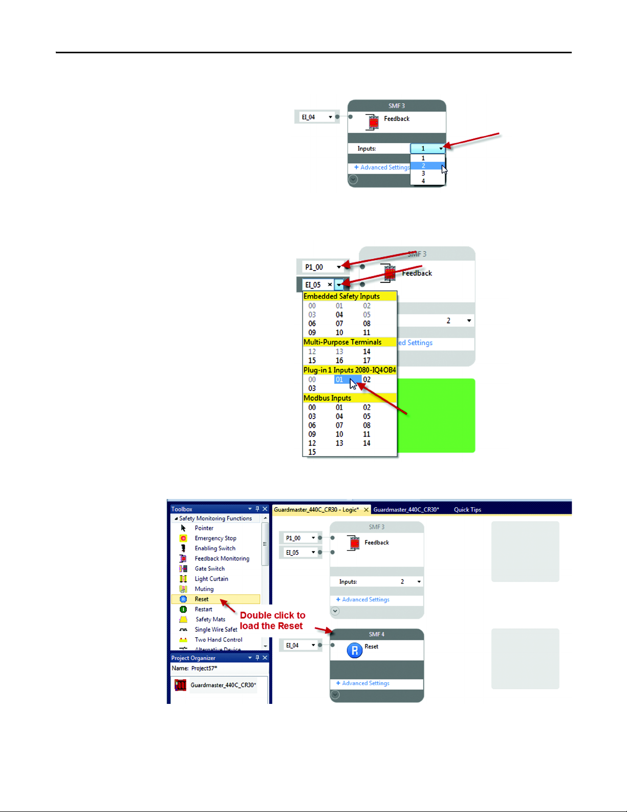
9. Modify the feedback block. Set the number of inputs to two.
10. Assign the feedback wiring terminal. Set the Input Terminals to Plug-in 00
and 01.
11. Load the reset block.
Rockwell Automation Publication 440C-QS001A-EN-P — January 2014 7
Page 10
Quick Start Guide
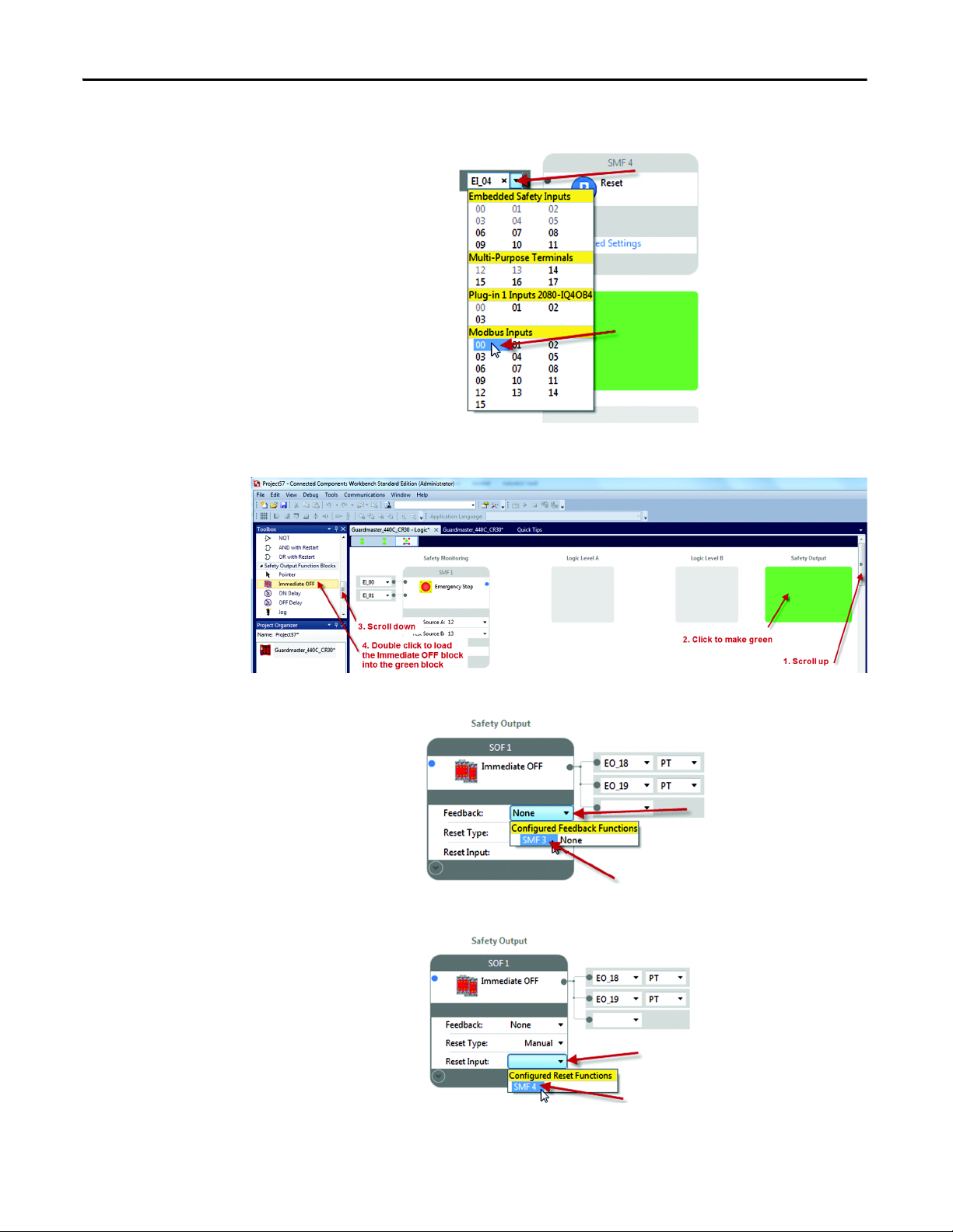
12. Change the reset input terminal to Modbus 00.
13. Load the Immediate OFF block.
14. Change the Feedback connection to SMF3 (Safety Monitoring Function 3).
15. Change the reset Input to SMF4 (Safety Monitoring Input 4).
8 Rockwell Automation Publication 440C-QS001A-EN-P — January 2014
Page 11
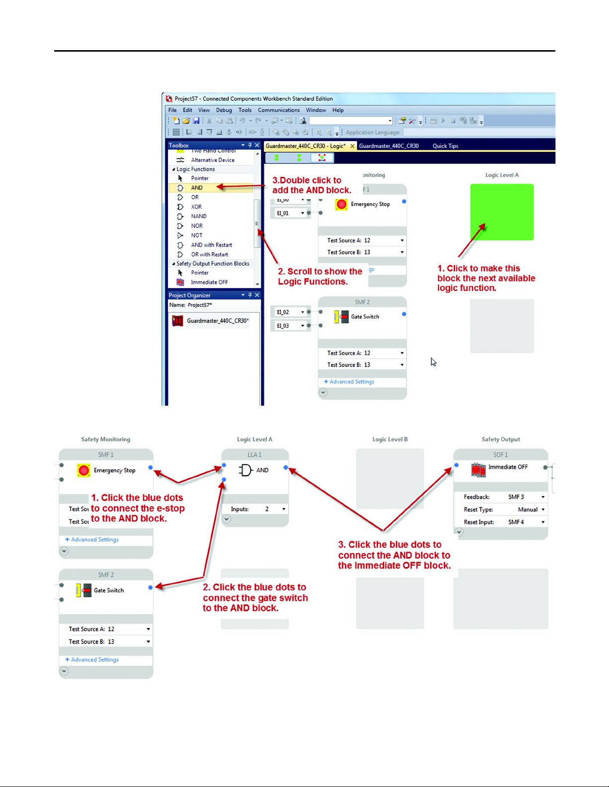
Quick Start Guide
16. Load an AND block.
17. Make the connections.
Rockwell Automation Publication 440C-QS001A-EN-P — January 2014 9
Page 12

Quick Start Guide
18. The final diagram should look like this.
The CCW automatically created a ‘Pass Through’ block in Logic Level B.
10 Rockwell Automation Publication 440C-QS001A-EN-P — January 2014
Page 13

Quick Start Guide
19. Configure the LEDs.
Input LEDs Type Filter Value
0 Terminal Status Terminal 00
1 Terminal Status Terminal 01
2 Terminal Status Terminal 02
3 Terminal Status Terminal 03
4 Not Used Not Used
5 Safety Monitoring Function Status SMF1
6 Safety Monitoring Function Status SMF2
7 Safety Monitoring Function Status SMF3
8 Safety Monitoring Function Status SMF4
Output LEDs
0 Safety Output Function Status SOF1
Rockwell Automation Publication 440C-QS001A-EN-P — January 2014 11
Page 14

Quick Start Guide
20. Save the Project.
12 Rockwell Automation Publication 440C-QS001A-EN-P — January 2014
Page 15

Quick Start Guide
21. Observe the Serial Port Settings.
Rockwell Automation Publication 440C-QS001A-EN-P — January 2014 13
Page 16

Quick Start Guide
We will be using these Modbus Addresses.
22. Download the project.
14 Rockwell Automation Publication 440C-QS001A-EN-P — January 2014
Page 17

Quick Start Guide
23. Click No to maintain project in Program mode.
24. Verify the Project.
• If this step is not completed, the CR30 will stop functioning after 24 hours.
The user can cycle the power to the CR30 and it will function again for
another 24 hours.
• If this step is completed, the CR30 will continue to function after 24 hours
and will run indefinitely.
• Verification can only take place while the CCW is connected to the CR30, and
the CR30 is in program mode.
Rockwell Automation Publication 440C-QS001A-EN-P — January 2014 15
Page 18

Quick Start Guide
25. The CCW generates the Safety Verification ID. Press OK to continue.
26. Confirm that the Verification ID is present in the CCW Project tab workspace
and the CR30 is returned to the Run mode.
Note that the Verification ID is not saved with the CCW project file. It is saved in
the CR30, so that when power is cycled, the user can upload the project from the
CR30 and view the verification ID and the CR30 functions beyond the 24 hour
limit.
Configuring the PanelView 600
In this application guide, the PanelView C600 is configured over the internet
connection. Open Internet Explorer and type in the IP address to the PanelView
600. In this application, the PanelView 600 has a fixed IP address of 192.168.2.14.
16 Rockwell Automation Publication 440C-QS001A-EN-P — January 2014
Page 19

Quick Start Guide
1. Click the Create and Edit button.
2. Set up Communications.
Rockwell Automation Publication 440C-QS001A-EN-P — January 2014 17
Page 20

Quick Start Guide
3. We will use the multi-state indicator to indicate the status of the
Guardmaster 440C-CR30 inputs, outputs and fault status. We will use a
multi-state pushbutton for the reset function. To do this, we need to create
tags, then place icons onto the screen and link the icons to the tags.
This guide will show how to set up one indicator and the reset button. The user
can follow these same steps to create additional indicators.
Create a tag for Safety Monitoring Function 1. This is the e-stop block.
4. Create a tag for reset button.
18 Rockwell Automation Publication 440C-QS001A-EN-P — January 2014
Page 21

Quick Start Guide
5. Put the SMF1 Indicator on the screen.
6. Double click on the multi-state indicator icon on the screen
Rockwell Automation Publication 440C-QS001A-EN-P — January 2014 19
Page 22

Quick Start Guide
7. The multi-state indicator has a default setting of four states plus an error
state.
8. We only want to use two states, plus the error state. Delete states three and
four.
9. Change the colors for the states.
20 Rockwell Automation Publication 440C-QS001A-EN-P — January 2014
Page 23

Quick Start Guide
10. Modify the text.
This first multi-state indicator will show the status of the e-stop function block.
When the multi-state value is zero, we want the text to show OFF and the
background color to be orange. When the value is one, we want to text to show
ON and the color to be green. If an error occurs we want the color to show red
and to display ERR.
11. Make the e-stop connection.
12. Add the reset button.
Rockwell Automation Publication 440C-QS001A-EN-P — January 2014 21
Page 24

Quick Start Guide
13. Set up the color, text and default states for the reset button.
14. Stretch the reset icon and make the Write Tag connection to the reset.
15. Add a Goto Config button.
22 Rockwell Automation Publication 440C-QS001A-EN-P — January 2014
Page 25

Quick Start Guide
16. Validate the screen and application
17. Save the file.
18. Go to the home page.
19. Run the application.
Rockwell Automation Publication 440C-QS001A-EN-P — January 2014 23
Page 26

Quick Start Guide
Verify Operation
1. Open the Logic editor in the CCW.
24 Rockwell Automation Publication 440C-QS001A-EN-P — January 2014
Page 27

Quick Start Guide
2. Confirm the LEDs are ON. The run LED is flashing.
3. Press and release the reset button on the PanelView C600 within 0.5 to 3 s
Rockwell Automation Publication 440C-QS001A-EN-P — January 2014 25
Page 28

Quick Start Guide
4. Confirm the LEDs.
5. Press the e-stop button.
The e-stop on the PanelView turns orange and shows OFF.
26 Rockwell Automation Publication 440C-QS001A-EN-P — January 2014
Page 29

Quick Start Guide
The Logic diagram shows the e-stop, AND and immediate OFF block are grey,
and the feedback block is green.
The LEDs are as follows:
Rockwell Automation Publication 440C-QS001A-EN-P — January 2014 27
Page 30

Quick Start Guide
Fault and Status Reporting
In this section, we will configure the PanelView C600 to display the status and
faults in the safety system.
1. The Modbus Mapping addresses for Status and faults is shown below.
2. Add the following tags to the PanelView C600.
28 Rockwell Automation Publication 440C-QS001A-EN-P — January 2014
Page 31

Quick Start Guide
3. Add the multi-state indicators for the faults.
4. Press the reset button to get the outputs on.
Create a short-circuit from terminal 0 to terminal 1.
5. The PanelView C600 will look like this.
Crossfault 12 – a crossfault occurred on terminal 12, which is Input Test Pulse A.
E-STOP OFF – since Input Test Pulse A is used by the e-stop SMF, it turns OFF.
Gate OFF – since Input Test Pulse A is also used by the Gate SMF, it turns OFF.
The fault causes the Output to turn OFF.
Bit 0 for e-stop provides the message on the “At least one circuit shorted to 24V
or another input circuit” when the mouse is moved over the e-stop or Gate SMF
on the CCW.
Remove the short circuit and cycle the e-stop and gate switch. The Guardmaster
440C-CR30 is now ready for the reset button.
Rockwell Automation Publication 440C-QS001A-EN-P — January 2014 29
Page 32

Quick Start Guide
30 Rockwell Automation Publication 440C-QS001A-EN-P — January 2014
Page 33

Page 34

Power, Control and Information Solutions Headquarters
Americas: Rockwell Automation, 1201 South Second Street, Milwaukee, WI 53204-2496 USA, Tel: (1) 414.382.2000, Fax: (1) 414.382.4444
Europe/Middle East/Africa: Rockwell Automation NV, Pegasus Park, De Kleetlaan 12a, 1831 Diegem, Belgium, Tel: (32) 2 663 0600, Fax: (32) 2 663 0640
Asia Pacic: Rockwell Automation, Level 14, Core F, Cyberport 3, 100 Cyberport Road, Hong Kong, Tel: (852) 2887 4788, Fax: (852) 2508 1846
www.rockwel lautomation.com
Rockwell Automation Support
Rockwell Automation provides technical information on the web to assist you in using its products.
At http://www.rockwellautomation.com/support
notes, sample code and links to software service packs, and a MySupport feature that you can customize to
make the best use of these tools. You can also visit our Knowledgebase at
http://www.rockwellautomation.com/knowledgebase
forums, software updates, and to sign up for product notification updates.
, you can find technical manuals, technical and application
for FAQs, technical information, support chat and
For an additional level of technical phone support for installation, configuration, and troubleshooting, we offer
Tec hCon ne ct
Rockwell Automation representative, or visit http://www.rockwellautomation.com/support/
SM
support programs. For more information, contact your local Allen-Bradley distributor or
.
Installation Assistance
If you experience a problem within the first 24 hours of installation, review the information that is contained in
this manual. You can contact Customer Support for initial help in getting your product up and running.
United States or Canada 1.440.646.3434
Outside United States or
Canada
Use the Worldwide Locator at http://www.rockwellautomation.com/support/americas/
phone_en.html, or contact your local Rockwell Automation representative.
New Product Satisfaction Return
Rockwell Automation tests all of its products to ensure they are fully operational when shipped from the
manufacturing facility. However, if your product is not functioning and needs to be returned, follow these
procedures.
United States Contact your distributor. You must provide a Customer Support case number (call the phone number above to
obtain one) to your distributor to complete the return process.
Outside United States Please contact your local Rockwell Automation representative for the return procedure.
Rockwell Automation and Allen-Bradley are trademarks of Rockwell Automation, Inc. Guardmaster is a registered trademark of Rockwell Automation, Inc.
Trademarks not belonging to Rockwell Automation are the property of their respective companies.
Publication 440C-QS001A-EN-P– February 2014 Copyright © 2014 Rockwell Automation, Inc. All rights reserved.
 Loading...