

Page 1
Installation Instructions
MiniSightt Photoelectric Sensors
Wide Angle
AC/DC Sensors
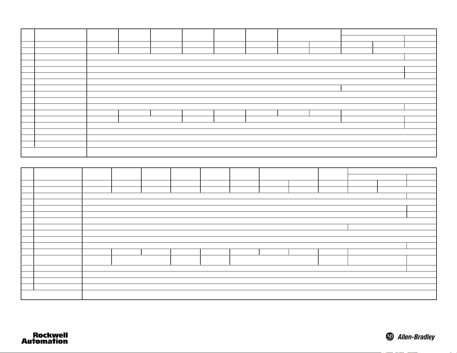
1 Catalog Number 4 2KL--U2T C -- X X 42KL--D1TC--XX 4 2KL-- W1T C -- X X 42KL--P2TC--XX 42KL--G1TC--XX 42KL--L2TC--XX 42KL--F2TCS--XX 42KL--F2TCL--XX
2 Sensing Distance 5m(16.4ft) 380mm (15in) 180mm (7in) 2m (6.6ft) Depends on Fiber Depends on Fiber 16mm (0.63in) 43mm (1.7in) 4m(13ft) 30m (98ft)
3 Outputs Two Wire Light/Dark Selectable —
4 Supply Voltage 21.6- -250V AC/DC
5 Load Current 100mA max —
6 Leakage Current 1.7mA rms max —
7 Power Consumption 4VA max
8 Response Time 8.3ms 16.6ms max
9 Approvals UL recognized, CSA, CE marked for all applicable directives
10 Protections Short Circuit, Reverse Polarity, False Pulse
11 Indicators Green = Power Yellow = Output Orange = 2.5X Margin, Flashing for Short Circuit Protection
12 Field of View
13 Transmitting LED Visible Red 660nm Infrared 880nm Visible Red 660nm Infrared 880nm Visible Red 660nm — Infrared 880nm
14 Sensitivity Adjustment Yes: 11 turn, clutch protected —
15 Operating Temperature -- 4Fto+158F(--20Cto+70C)
16 Housing—Cover—Lens Material Noryl N190—Radel R5000—Acrylic
17 Operating Environment NEMA 4X, 6P, IP67, withstands 8270kPa (1200 psi) washdown
Catalog Number Key—XX could equal
Retroreflective Diffuse
1.5_ 5_ 18_ 1.5_
A2 = 2m, 300Vcable F4 = pigtail w/4-pin DC micro QD G3 = pigtail w/3-pin AC micro QD Y4= pigtail w/4-pin DC pico QD X4 =custom 4-pin connector
Not all variations available.Contact factory for availability.
Diffuse
Polarized
Retroreflective
Large Aperture
Fiber Optic
Depends on Fiber Depends on Fiber — —
Small Aperture
Fiber Optic
Visible Red Fixed Focus
42KL--RTCV--XX
Transmitted Beam
Receiver Source
42KL--RTC--XX 42KL--E1QZB--XX
7_
Wide Angle
DC Sensors
1 Catalog Number 42KL--U2LB--XX 42KL--D1LB--XX 42KL--W1LB--XX 42KL--P2LB--XX 42KL--G1LB--XX 42KL--L2LB--XX 42KL--F2LBS--XX 42KL-- F2LBL--XX 42KL--F3LBS--XX
2 Sensing Distance 5m (16.4ft) 380mm (15in) 180mm (7in) 2m(6.6ft) Depends on Fiber Depends on Fiber 16mm (0.63in) 43mm (1.7in) 16mm (0.63in) 4m (13ft) 30m (98ft)
3 Outputs NPN/PNP Light/Dark Selectable —
4 Supply Voltage 10.8- -30V DC
5 Load Current 100mA max —
6 Leakage Current 0.1mA max —
7 Power Consumption 1.5W max
8 Response Time 1ms max 15ms max
9 Approvals UL, CSA, CE marked for all applicable directives
10 Protections Short Circuit, ReversePolarity,False Pulse
11 Indicators Green = Power Yellow = Output Orange = 2.5X Margin, Flashing for Short Circuit Protection Green = Power
12 Field of View
13 Transmitting LED Visible Red 660nm Infrared 880nm Visible Red 660nm Infrared 880nm Visible Red 660nm Visible Green
14 Sensitivity Adjustment Yes: 5 turn, clutch protected —
15 Operating Temperature -- 4 Fto+158F(--20Cto+70C)
16 Housing—Cover—Lens Material Noryl N190—Radel R5000—Acrylic
17 Operating Environment NEMA 4X, 6P, IP67, withstands 8270kPa (1200 psi) washdown
Catalog Number Key—XX could equal
When using the transmitted beam sensing mode in high noise (EMF) applications, it is recommended that the 42KL--RxxV receiver be used whenever possible. This will prevent the sensor from “locking on” due to high line voltage
spikes.
Retroreflective Diffuse
1.5_ 5_ 18_ 1.5_
A2 = 2m, 300Vcable F4 = pigtail w/4-pin DC micro QD G3 = pigtail w/3-pin AC micro QD Y4= pigtail w/4-pin DC pico QD X4 =custom 4-pin connector
Not all variations available.Contact factory for availability.
Diffuse
Polarized
Retroreflective
Large Aperture
Fiber Optic
Depends on Fiber Depends on Fiber — — —
Small Aperture
Fiber Optic
Visible Red Fixed Focus
Visible Green
Fixed Focus
42KL--RLBV--XX
525nm
Transmitted Beam
Receiver Source
42KL--RLB--XX 42KL-- E1EZB--XX
7_
— Infrared 880nm
Page 2
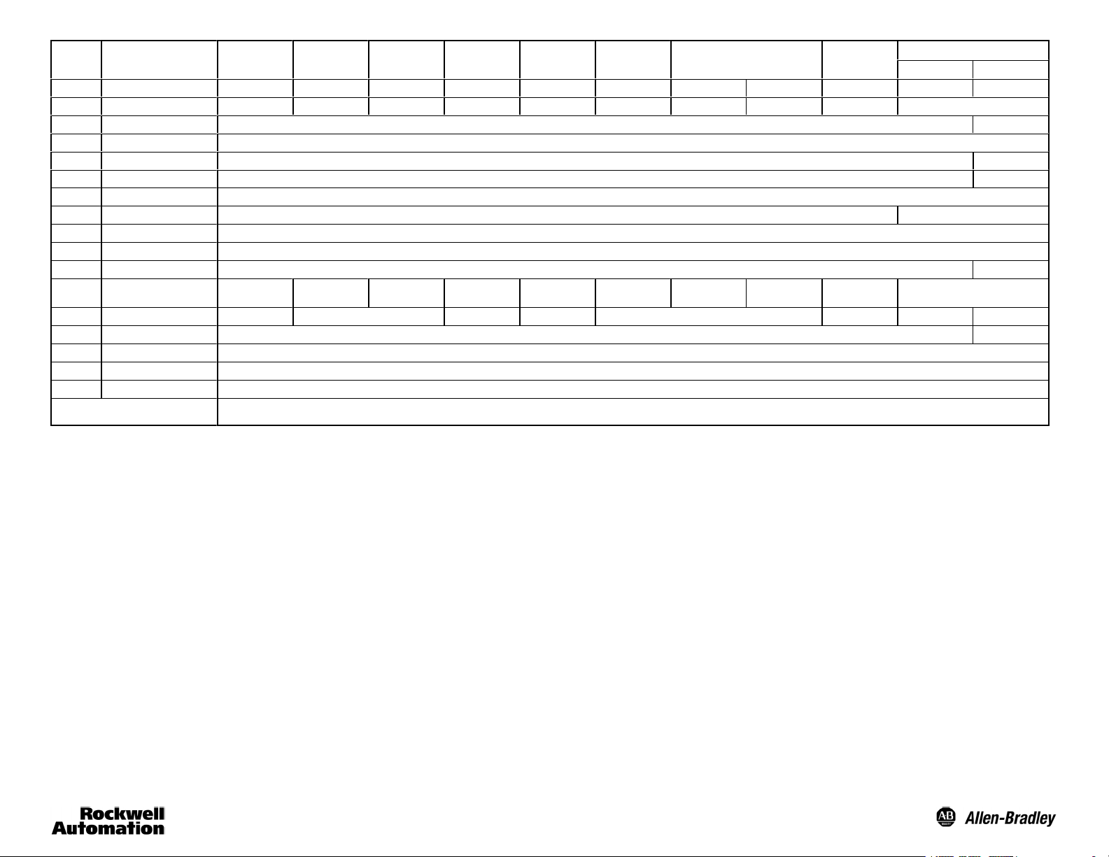
High Speed
DC Sensors
1 Catalog Number 42KL--U2LBQ--XX 42KL- -D1LBQ--XX 42KL--W1LBQ--XX 42KL--P2LBQ--XX 42KL- -G1LBQ--XX 42KL--L2LBQ--XX 42KL-- F2LBSQ--XX F2LBLQ--XX 42KL--F3LBSQ--XX 4 2 K L -- RLB Q -- X X 42KL--E1EZBQ--XX
2 Sensing Distance 2.5m (8.2ft) 190mm (7.5in) 90mm(3.5in) 1m(3.3ft) Depends on Fiber Depends on Fiber 16mm (0.63in) 43mm(1.7in) 16mm (0.63in)
3 Outputs NPN/PNP Light/Dark Selectable —
4 Supply Voltage 10.8--30V DC
5 Load Current 100mA max —
6 Leakage Current 0.1mA max —
7 Power Consumption 1.5W max
8 Response Time 300smax
9 Approvals UL recognized, CSA,CE marked for all applicable directives
10 Protections Short Circuit, Reverse Polarity, False Pulse
11 Indicators Green = Power Yellow = Output Orange = 2.5X Margin, Flashing for Short Circuit Protection Green = Power
12 Field of View
13 Transmitting LED Visible Red 660nm Infrared 880nm Visible Red 660nm Infrared 880nm Visible Red 660nm Visible Green 525nm — Infrared 880nm
14 Sensitivity Adjustment Yes:11 turn, clutch protected —
15 Operating Temperature -- 4 Fto+158F(--20Cto+70C)
16 Housing—Cover—Lens Material Noryl N190—Radel R5000—Acrylic
17 Operating Environment NEMA 4X, 6P,IP67 withstands 8270kPa (1200 psi) washdown
Catalog Number Key—XX could equal
Retroreflective Diffuse
1.5_ 5_ 18_ 1.5_
A2 = 2m, 300V cable F4 = pigtail w/4-pin DC microQD G3 = pigtail w/3-pin AC micro QD Y4 = pigtail w/4-pin DC pico QD X4 =custom 4-pin connector
Not all variations available. Contact factory for availability.
Wide
Angle Diffuse
Polarized
Retroreflective
Large Aperture
Fiber Optic
Depends on Fiber Depends on Fiber — — —
Small Aperture
Fiber Optic
Visible Red Fixed Focus
Visible Green
Fixed Focus
Transmitted Beam
Receiver Source
15m (49ft)
8ms max
7_
—
Page 3

English Deutsch Français Italiano Español Portuguêas
Operating Distance Selection
The maximum operating distance is based on
installing the sensor in a relatively clean
environment. Normal industrial environments
actually range from moderately dusty toextremely
dirty. Greater operating margin may be required
which can be obtained by reducing the operating
distance of thecontrol.
Indicators
Green on indicates power on.
Yellow on indicates output is energized.
Orange on indicates 2.5X margin.
Orange flashing indicates short circuit or overload.
Red
Orange
Black
White
Green
Brown
Blue
D.O. = DarkOperate
L.O. = Light Operate
Polarized Retroreflective
Diffuse
Glass Fiber Optic
Plastic Fiber Optic
Fixed Focus Diffuse
Transmitted Beam Receiver
Transmitted Beam Source
Operating Distance
Operating Margin
Load
ATTENTION
Always remove power from the sensor before
removing short circuit.
Wahl der Reichweite
Die maximale Reichweitebasiert auf einer
Installation des sensors in einer relativ sau-beren
Umgebung. Normale industriellle Umgebungen sind
zumeist jedoch relativstaubig bis äußerst
verschmutzt. In diesem Fall ist eine größere
Betriebsmarge erforderlich, die durch einen
geringeren Abstand erzielt werden kann.
Leuchtanzeigen
Grünes Dauerlicht: Spannung eingeschaltet.
Gelbes Dauerlicht: Ausgang aktiviert.
Oranges Dauerlicht: 2,5fache Marge.
Oranges Blinklicht: Kurzschluß oder Überlast.
Rot
Orange
Schwarz
Weiß
Grün
Braun
Blau
D.O. = dunkelschaltend
L.O. = hellschaltend
Reflexionslichtschranke, polarisiert
Lichttaster
Glaslichtleiter
Kuuststofflichtleiter
Lichtaster mit fester fokussierung
Einweglichtschranke, Empfänger
Einweglichtschranke, Sender
Reichweite
Betriebsmarge
Last
ACHTUNG
Vor dem Beheben eines Kurzschlusses
immer die Stromzufuhr zum Sensor aus-schalten
Choix de la Distance de Fonctionnement
La distance maximale de fonctionnement dépend
de la propreté relative de l’environnement
d’installation de la cellule. A vrai dire, les
environnements industriels normaux vont de
modérément poussiéreux à extrêmement sales.
Une marge d’opération plus grande peut être
nécessaire et s’obtient en réduisant la distance
opérationnelle du contrôle.
Indicateurs
Vert allumé indique : sous tension.
Jaune allumé indique : sortie activée.
Orange allumé indique : marge de 2,5 X.
Orange clignotant indique : court-circuit ou
surcharge.
Rouge
Orange
Noir
Blanc
Vert
Brun
Bleu
D.O. = Déséclairement
L.O. = Eclairement
Réflexe polarisé
Proximité
Fibre optique de verre
Fibre optique en plastique
Proximité à focale fixe
Récepteur de faisceaux transmis
Émetteur de transmission de faisceaux
Distance de fonctionnement
Marge de fonctionnement
Charge
ATTENTION
Toujours mettre la cellule hors tension avant de
supprimer un court-circuit.
Selezione Distanzia Operative
La massima distanza di funzionamento si basa
sull’installazione del sensore in un ambiente
relativamento pulito. Gli ambienti industriali normali
vanno in verità da moderatamente polverosia
estremamente sporchi. Potrebbe esserenecessario
un margine di funzionamento superiore che si può
ottenere riducendo la distanza operativa del
controllo.
Indicatori
Verde acceso indica alimentazione.
Giallo acceso indica uscita energizzata.
Arancio acceso indica margine 2,5X.
Arancio lampeggiante indica cortocircuito o
sovraccarico.
Rosso
Arancio
Nero
Bianco
Verde
Marrone
Azul
D.O.=Azione su buio
L.O.=Azione su luce
Retroriflessivo polarizzato
Diffuso
Fibra ottica in vetro
Fibra ottica in plastica
Tasterfocalizzato
Ricevitore raggio trasmesso
Sorgenti raggi trasmessi
Distanza operativa
Margine operativo
Carico
ATTENZIONE
Prima di togliere il cortocircuito rimuovere sempre
la corrente dal sensore.
Selección de Distancia de Operación
La distancia máxima de operación se basa en la
instalación del sensoren un ambiente
relativamente limpio.Losambientesindustriales
normales fluctúan entre moderadamente
polvorosos a extremadamente sucios. Es posible
queserequieraunmargendeoperaciónmayor,el
cual puede obtenerse reduciendo la distancia
operativa del control.
Indicadores
El indicador verde encendido indica que la
alimentación eléctrica está conectada.
El indicador amarillo encendido indica que la salida
está activada.
El indicador anaranjado encendido indica un
margen de 2.5X.
El indicador anaranjado parpadeando indica
cortocircuito o sobrecarga.
Rojo
Anaranjado
Negro
Blanco
Verde
Marrón
Azul
D.O. = Operación oscura
L.O. = Operaciónclara
retro-reflector polarizado
Difuso
Receptor de rayos transmitidos
Fuentes de rayos transmitidos
Distancia de operación
Margen de operación
Carga
ATEN CION
Siempre desconecte la alimentación eléctrica del
sensor antes de retirar el cortocircuito.
Seleção da Distância de Operação
A distância máxima de operação é baseada na
instalação do sensor em ambiente relativamente
limpo. Os ambientes industriais normais
efetivamente apresentam condições entre
moderadamente poeirentos e extremamente sujos.
Poderá ser exigida uma maior margem de
operação, podendo ser realizada pela redução da
distânciadeoperaçãodocontrole.
Indicadores
Verde iluminado indica alimentação ligada.
Amarelo iluminado indica saída energizada.
Laranja iluminado indica margem de 2,5X.
Laranja iluminado indica curto circuito ou
sobrecarga.
Vermelho
Laranja
Preto
Branco
Verde
Marrom
Azul
D.O. = Operado pela Escuridão
L.O. = Operado pela Luz
Retrorefletivo Polarizado
Difuso
Fibra Ótica de Vidro
Fibra Ótica Plástica
Feixe Difuso--Reflexivo, com Foco Fixo
Receptor de Feixe Transmitida
Fontes de Feixe Transmitida
Distância de Operação
Margem de Operação
Carga
ATENÇÃO
Sempre remova a alimentação do sensor antes de
remover um curto circuito.
English Deutsch Français Italiano Español Portuguêas
1 Catalog Number Bestellnummer Référence de Commande Numero di Catalogo Número de Catálogo Número do Catálogo
2 Sensing Distance Reichweite Distance de Détection Distanza di Rilevamento Dispositivo Sensor Distância de Sensoriamento
3 Outputs Ausgang Sortie Uscita Salida Saída
4 Supply Voltage Versorgungsspannung Tension d’Alimentation Tensione di Alimentazione Voltaje de Alimentación Voltagemde Alimentação
5 Load Current Laststrom Courant de Charge Corrente di Carico CorrientedeCarga Corrente de Carga
6 Leakage Current Ruhestrom Courant de Fuite Corrente di Dispersione CorrientedeFuga Corrente de Dispersão
7 Power Consumption Leistungsaufnahme Consommation Consumo Potenza Consumode Alimentación eléctrica Consumo de Energia
8 Response Time Ansprechzeit Temps de Réponse Te mp o d i R isposta Tiempo de Respuesta Tempo de Resposta
9 Approvals Approbation Homologations Approvazioni Aprobaciones Aprovações
10 Protections Schutzart Protections Protezioni Protecciones Proteções
11 Indicators Anzeigen Indicateurs Indicatori Indicadores Indicadores
12 FIeld of View Sichtbereich AngledeVisée Campo di Visione CampodeVisión CampodeVisão
13 Transmitting LED Lichtquelle (LED) LED de Transmission LED di Trasmissione LED de Transmisión LED de Transmissão
14 Sensitivity Adjustment Empfindlichkeitseinstellung Réglage de Sensibilité Regolazione di Sensibilità Ajuste de Sensibilidad Ajuste de Sensibilidade
15 Operating Temperature Betriebstemperatur Température de Fonctionnement Temperatura di Funzionamento Temperatura de Operación Temperaturade Operação
16 Housing—Cover—Lens Material Gehäusematerial/Werkstoff der
17 Operating Environment Betriebsumgebung Environnement Opérationnel Ambiente Operativo Ambiente de Operación Ambiente de Operação
Abdeckung/Linsenmaterial
PHOTOSWITCHRis a registered trademark
of Rockwell Automation/Allen-Bradley.
Matériaux du Boîtier/du Couvercle/des Lentilles Materiale dell’Involucro/per la Copertura/delle Lenti Material del Alojamiento/de la Cubierta/del Lente Material da Caixa/Tampa/Lente
Publication PA--9602(E)
June 2001
PrintedinUSA
Page 4

Sensor Wiring Diagrams
11--30V DC Sensors
NPN/PNP
Cable
Brown
White
Black
Blue
Load
Load
1
+
--
Brown
2
White
Load
Black
4
3
Load
Blue
Micro Pico
+
1324
--
4
2
1
3
Transmitted Beam Source
1
TT
Brown
Blue
+
--
Cable
Brown
Blue
+
--
4
2
3
Micro Pico
1324
2
1
4
3
22--250V AC/DC Sensors
AC Wiring
Red/Black
Brown
L1
~
Blue
L2
Load Load Load
~
2
Green
1
Red/White
3
L1
~
32
L2
1
~
Cable
DC Wiring
Cable
Brown
Blue
Red/Black
+
--
2
1
Green
Red/White
3
+
32
--
1
Transmitted Beam Source
AC Wiring
T
Cable
Brown
Blue
2
L1
L2
~
~
T
Red/Black
Green
1
3
Red/White
L1
~
32
L2
1
~
DC Wiring
Brown
TT
Blue 3
--
Red/Black
2
Green
1
Red/White
Cable
++
32
--
1
Sensor Dimensions—mm (inches)
DC Sensors
18 (0.71) Dia.
M18 x 1mm
thread
18mm Mounting Nut
(supplied with sensor)
15
(0.60)
10in/lbs max torque
AC/DC Sensors
18 (0.71) Dia.
M18 x 1mm
thread
18mm Mounting Nut
(supplied with sensor)
Note: All sensors supplied with an 18mm mounting nut (catalog number 75012--097) except fiber optic sensors 42KL--G1xxx and 42KL--L2xxx. They will use an 18mm mounting nut (catalog number 75012 --025).
15
(0.60)
10in/lbs max torque
39.6
(1.56)
12.2 (0.48)
24.1
(0.95)
3.5 (0.13)
Dia. Thru for #4 screw
52.3
(2.06)
12.2 (0.48)
24.1
(0.95)
3.5 (0.13)
Dia. Thru for #4 screw
152.4
(6)
152.4
(6)
30.7
(1.21)
30.7
(1.21)
4-pin Micro Style
Quick Disconnect
3-pin Micro Style
Quick Disconnect
14.48
(0.57)
14.48
(0.57)
12.7
(0.49)
12.7
(0.49)
62.6
(2.46)
75.3
(2.96)
2m (6.56ft) 4-conductor cable
2m (6.56ft) 2-conductor cable
Light/Dark
Operate Switch
Margin/Short
Circuit Indicator
(Orange)
Light/Dark
Operate Switch
Margin/Short
Circuit Indicator
(Orange)
Sensitivity
Adjustment
Power Indicator
(Green)
Output Indicator
(Yellow)
Sensitivity
Adjustment
Output Indicator
(Yellow)
Power Indicator
(Green)
Page 5

Sensor Dimensions—mm (inches) (continued)
LargeApertureFiberOpticSensors
18 (0.71) Dia.
16.6
(0.65)
M18 x 1mm thread
25.3
(0.99)
Catalog number
75012--097 max
torque = 10in/lbs
Fiber Retaining Clip
(supplied with sensor)
20.5
(0.80)
Small Aperture Fiber Optic Sensors
18 (0.71) Dia.
M18 x 1mm thread
16.3
(0.64)
Catalog number
75012--025 max
torque = 10in/lbs
12.2
(0.48)
3.5 (0.13) Dia. Thru
23
(0.90)
Accessories—mm (inches)
Right Angle Side Mounting Bracket #60--2663
Fiber Retaining
Clip
Grooved Fiber
Optic End Tip
NOTE: MiniSightt large aperture fiber optic
sensors require Series “C” Glass Fiber
Optic cables with grooved control end tips.
Fiber Retaining Cap (supplied with sensor)
Turn clockwise to secure fiber optic cables.
Plastic Fiber Optic Cable
2.2 (0.09) jacket diameter or control end tip
NOTE: Small aperture fiber optic cables are also available with 2.2mm (0.09in) diameter control
end tips for use with these small aperture sensors. Refer to the Allen-Bradley Sensor
catalog.
Right Angle Mounting Bracket #60--2664
Right Angle Mounting Bracket #60--2657
NOTE: For smaller fiber optic cables with jacket diameters of
1.0/1.25mm (0.04/0.05in), catalog number 61--6731 adapto
are required, sold separately.
Adaptor Cap
Adaptor
Retaining Clip
1.25mm Diameter
Cable
2.2mm Diameter
Cable Adaptor
#4 Mounting Screw
(supplied with bracket)
1.5
(0.05)
45.5
(1.79)
90
20
24.1R
(0.95)
18mm Mounting Nut
(supplied with sensor)
Catalog number 75012-- 097
max torque = 10in/lbs
Catalog number 75012-- 097
80
20
31.8
(1.25)
20.3
11.9
(0.80)
(0.47)
20.1
(0.79)
4.6 (0.18)
3.1 (0.13) Dia
40.4
3.4
(1.59)
(0.13)
30
18mm Mounting Nut
(supplied with sensor)
(0.10)
45.5
(1.79)
90
18.4 (0.72) Dia
2.7
24.1R
(0.95)
20
max torque = 10in/lbs
30
31.8
(1.25)
25.4
(1.0)
3.1 (0.13) Dia
3.4
(0.13)
38.1
(1.5)
40.4
(1.59)
90_
1.5 (0.06)
15.7
(0.62)
4.6
(0.18) 4 Places
30_
42.4
(1.67)
3Places
18.5 (0.73) Dia.
14.3
(0.75)
12.7
(0.50)
R24
(0.95)
35.8
(1.41)
15.7
(0.62)
29
(1.14)
Page 6

Accessories—mm (inches) (continued)
Straight Mounting Bracket #60--2656
18mm Mounting Nut
(supplied with sensor)
Catalog number 75012-- 097
max torque = 10in/lbs
30_
3Places
18.5
(0.73) Dia.
R24
(0.62)
R15
(0.59)
(0.95)
15.7
29
(1.14)
(2.10)
12.7
(0.50)
53
70
(2.78)
1.5
(0.06)
52
(2.04)
2Places
(0.18)
4Places
4.6
42.4
(1.67)
Fiber Optic Cable Selection
Apertures
Snap-on apertures for Transmitted Beam applications are available for MiniSight sensors to detect small objects. Select an aperture slot size that will be blocked by the object being detected
for best results. An aperture should be placed on both the source
and receiver units for proper operation.
1mm slotted aperture, Qty. 20: #60--2673
2mm slotted aperture, Qty. 20: #60--2674
4mm slotted aperture, Qty. 20: #60--2675
Aperture assortment, Qty. 4 each—1mm, 2mm, 4mm: #60--2676
Snap-on Aperture
Quick-Disconnect Cordsets
DC MiniSight Sensors AC/DC MiniSight Sensors
All quick-disconnect versions of DC
MiniSight sensors use 4-conductor
micro or pico style quick-disconnect
cordset. These cables are PVC
insulated and are supplied with
gold-plated female contacts and
nickel-plated brass hardware.
Catalog
Number
889D--F4EC--2 Heavy duty 2m (6.6ft) with
889D--F4EC--5 Heavy duty 5m (16.4ft) with
889D--F4AC--2 General purpose 2m (6.6ft)
889D--F4AC--5 General purpose 5m (16.4ft)
DC Quick-Disconnect
Cable Description
protective shield
protective shield
nonshielded
nonshielded
AC/DC MiniSight sensors with
quick-disconnect use 3-conductor
micro style quick-disconnect cables.
These cables are PVC insulated and
are supplied with gold-plated female
contacts and nickel-plated brass
hardware.
Catalog
Number
889R--F3AEA--2 Heavy duty 1.8m (6ft) with
889R--F3AEA--5 Heavy duty 3.6m (12ft) with
889R--F3AEA--10 Heavy duty 6m (20ft) with
DC Quick-Disconnect
Cable Description
protective shield
protective shield
protective shield
Glass Fiber Optic Cables Plastic Fiber Optic Cables
Sensing Mode Glass Fiber Diameter Typical Fiber Model Maximum Range Sensing Mode Glass Fiber Diameter Typical Fiber Model Maximum Range
Diffuse
Transmitted Beam
Hundreds of other fiber optic cabes are available. Consult the Allen-Bradley Fiber Optic Cable addendum catalog, publication C114--CA004A--EN--P.
3.1 (0.125) 43GR--TBB25SL 38 (1.5)
1.1 (0.046) 43GR--TFS10ML 21(0.8) 0.5 (0.020) 43PR--NGS53ZM 12.7 (0.5)
3.1 (0.125) 43GT--TBB25SL 457 (18)
1.1 (0.046) 43GT -- T F S -- 1 0 M L 152 (6) 0.5 (0.020) 43PT--NBS52FM 38 (1.5)
Diffuse
Transmitted Beam
1 (0.040) 43PR--NES57ZS 31 (1.2)
1 (0.040) 43PT--NJS56FS 127 (5)
 Loading...