

Page 1
42KD Miniature Sensor
IMPORTANT
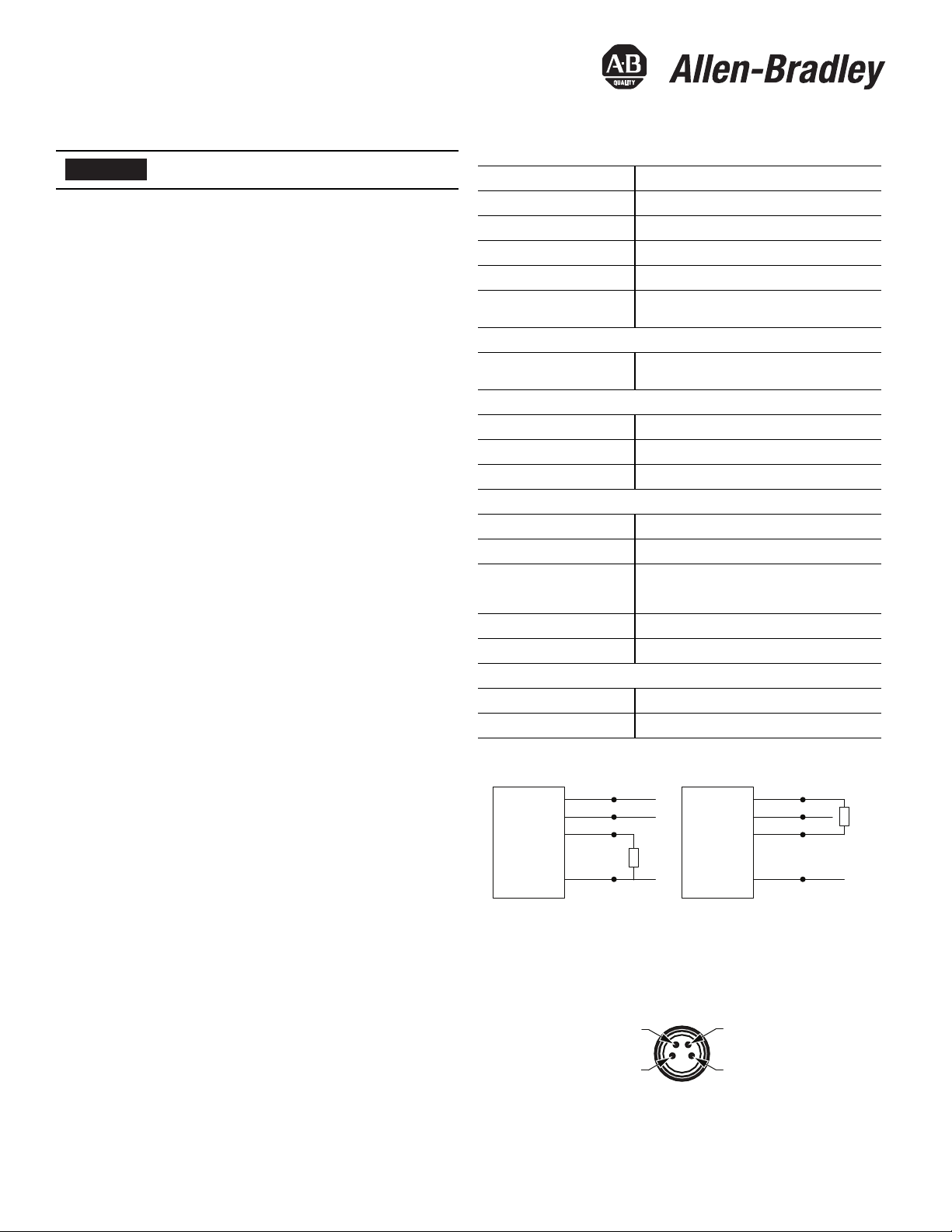
3
2
1
4
M8 Male
Installation Instructions
Original instructions in English
SAVE THESE INSTRUCTIONS FOR FUTURE USE.
Description
The 42KD Miniature sensor provides a solution for applications in very
small confined spaces. The 42KD sensor is the smallest sensor in the
Photoelectric sensor portfolio. It offers various sensing modes, sensing
distances, auto PNP/NPN, push button/remote teach, and push
button lock options. Although miniature in size the features and
performance on this sensor are reliable and competitive.
The 42KD is available in visible red LED models in polarized
retroreflective and fixed/adjustable background suppression sensing
modes. The teach button simplifies the setup process and even
provides the option to remote teach the sensor. The sensor also has
the option of light operate (L.O.) or dark operate (D.O.). All 42KD
sensors have a unique “auto PNP/NPN” output which reduces stocking
cost and simplifies selection, installation, and maintenance.
The 42KD is an excellent solution to a broad range of applications
including industries such as automotive, packaging, and material
handling. These features make the 42KD sensor easy to apply in
challenging applications, especially where space is a limitation.
Features
• Smallest sensor in the Rockwell Automation portfolio
• Auto NPN/PNP output
• Easy setup of switch points using teach button
• External teach capability
• IP67 enclosure
• Self-contained sensor
• Mounting accessory included with product
Specifications
Certifications CE Marked for all applicable directives
Enclosure Type Rating IP67
Operating Temperature [C(F)] -20…+50° (-4…+122°)
Storage Temperature [C(F)] -20…+80° (-4…+176°)
Vibration 10…55 Hz, 1 mm amplitude, meets or exceeds IEC 60947-5-2
Shock
Optical
Indicator LEDs
Electrical
Operating Voltage 10…30V DC
No Load Supply Current LED models: ≤30 mA
Protection Type Short circuit and reverse polarity
Outputs
Response Time 500 μs
Output Type Auto PNP/NPN
Output Function
Output Current ≤50 mA
Switching Frequency 1000 Hz
Mechanical
Housing Material PUR
Lens M aterial PMM A
30 g with 11 ms pulse duration, meets or exceeds
IEC 60947-5-2
Green: Operating voltage on;
Yellow: Object detected/switching output active
Complimentary light and dark operate via push button and
remote teach fixed background suppression models;
Complimentary light and dark operate via remote teac h
Wiring Diagrams
Input
+V
Load
-V
Brown (1)
White (2)
Black (4)
Blue (3)
PNP Operation NPN Operation
+V
Input
Load
-V
Brown (1)
White (2)
Black (4)
Blue (3)
Pinouts
The quick-disconnect is shown below. The pin numbers correspond to
male connectors on the sensor.
Rockwell Automation 42KD-IN001A-EN-P—Octo ber 2014
Page 2
2 42KD Miniature Sensor
2 m cable
Teach-in
8 (0.31)
5.5 (0.22)
Emitter
Receiver
LED 2
21.1
(0.83)
3.3
(0.13) dia.
3.3
(0.13)
18.3
(0.72)
LED 1
8 (0.31)
4.6 (0.18)
4.9
(0.19) dia.
2.6
(0.10) dia.
14.6 (0.57)
2.8
(0.11)
M8
M8 with
pico pigtail
Teach-in
LED 2
LED 1
8 (0.31)
21.1
(0.83)
4.6 (0.18)
4.9
(0.19) dia.
2.6
(0.10) dia.
3.3
(0.13) dia.
3.3
(0.13)
18.3
(0.72)
14.6 (0.57)
2.8
(0.11)
8 (0.31)
5.5 (0.22)
Emitter
Receiver
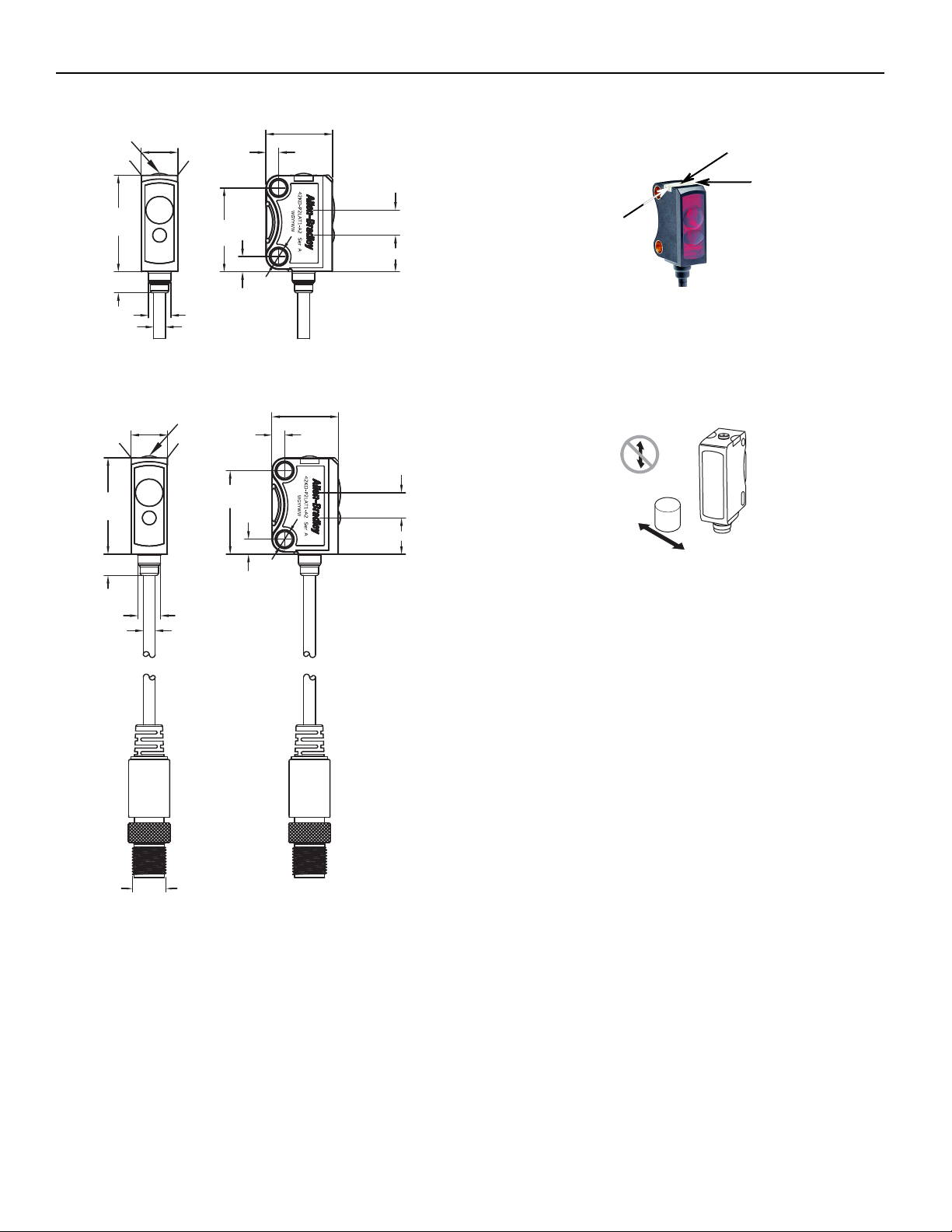
Teach button
LED indicator
LED indicator
Tar get
Dimensions [mm (in.)]
Sensor User Interface
Familiarize yourself with the LED indicators.
Mounting the Sensor
Securely mount the sensor on a firm, stable surface or support. An
application subject to excessive vibration or shifting may cause
intermittent operation. For installation convenience, Rockwell
Automation offers a wide range of mounting brackets (see Accessories
section for more detail).
Note: Due to the detection method, targets travelling horizontally to
the sensor’s optics are detected. Targets travelling vertically
may not be accurately detected. For reliable background
suppression, a minimum separation distance is recommended
between the target and the background.
42KD Miniature Sensor Configuration
Polarized Retroreflective and Adjustable Background
Suppression
The 42KD is configured using the push button or Remote Teach, and
the LED indicators on the sensor. Four features can be configured:
• Standard or precision teach for sensitivity/sensing range
• Light operate (LO) or dark operate (DO) output
• Auto PNP/NPN, dedicated NPN or dedicated PNP
• Push button lock/unlock
The sensor output is disabled during Teach.
Teach Interface
Default Settings:
The factory default settings are as follows:
Sensing Range: Maximum Setting
Output Type: Auto PNP/NPN. In Auto PNP/NPN mode, the sensor
continuously monitors the load connection and automatically
configures the output to PNP or NPN.
Rockwell Automation 42KD-IN001A-EN-P—October 2014
Teach Sensitivity/Sensing Range
The default setting is the maximum sensitivity/range.
Teaching the sensitivity/sensing range is a two-step process: teach the
background (first condition) and teach “target” (second condition).
Switching threshold for output ON vs. OFF is set in between the two
conditions.
Page 3

Standard Teach:
Background
t > 3 s
IMPORTANT
Tar get
Background
t < 0.5 s
t > 6 s
t < 0.5 s
1. To teach the background (first condition):
Align the sensor to the background. Press and
hold button for three seconds until yellow LED
starts flashing. Release the button. The first
condition has now been taught.
2. Teach “target” (second condition):
In the case of multiple reflectivity targets,
choose the darkest/least reflective target
placed in its farthest position for set up.
Insert the target between the sensor and the
background. Press and release the button. The
teach process is complete.
If the push button is not pressed within 30
seconds, the sensor exits teach mode and returns
to RUN mode without learning the new setting.
If there’s no background surface in the field of view in Step 1, the
switching threshold will be set between the distance to the target and
the maximum sensing range. The sensor can also be taught by
teaching the target as the first condition and background as the
second condition.
Precision Teach: For a more precise setting with a smaller hysteresis,
teach the sensor to the target in step 1 and keep the target present in
step 2).
Restore to factory default setting of maximum range: Perform
steps 1 and 2 with “no target” in the sensor’s field of view and nothing
in the background.
Teach Light Operate (L.O.) or Dark Operate (D.O.)
The default setting of the output is dark operate (D.O.)
L.O. setting means that output turns ON when the target is detected. If
the application requires the output to turn OFF when the target is
detected, the setting may be changed to dark operate (D.O.).
1. To access the teach output mode setting:
Press and hold button for six seconds until the
green LED starts flashing. Release the button. The
current setting is indicated by the yellow LED:
L.O.: Yellow LED ON
D.O.: Yellow LED OFF
42KD Miniature Sensor 3
2. To change the sensor output mode setting:
Press and release the button within ten seconds to
toggle from L.O. to D.O., the selection indicated by
the yellow LED.
The sensor retains the setting per the last button
depression and returns to the RUN mode ten
seconds after the last button is depressed.
Output Type Selection: Auto PNP/NPN, Dedicated NPN,
Dedicated PNP
The default setting is Auto PNP/NPN. The sensor monitors the load
connection and automatically configures for proper operation, i.e.
PNP or NPN. If no load is connected, the sensor defaults to PNP. The
following applications are covered with dedicated PNP or dedicated
NPN selection:
a. Parallel wiring of multiple sensor outputs: select dedicated PNP
or dedicated NPN setting, as needed.
b. If the load is connected for NPN configuration but to a power
supply other than that to the sensor or via a load enabling
contact (e.g. a relay contact in series with the load), select
dedicated NPN.
Selection can be made as follows:
1. To access output type: Press and hold the push button for nine
seconds (until both LEDs start flashing synchronously). Upon
button release, the current setting of output type is indicated by
the slow flashing of the LED(s) as follows:
• Auto PNP/NPN: both LEDs flashing
• Dedicated NPN: green LED flashing
• Dedicated PNP: yellow LED flashing
2. To change outp ut type: Press and release the push button within
10 seconds to select desired type. Each button activation cycles to
the next output setting. The type selected is indicated by the LEDs.
The sensor retains the setting per the last button depression and
returns to the RUN mode 10 seconds after the last button is
pressed.
Push Button Lock/Unlock
The push button or remote teach (RT) can be used to prevent
unauthorized users from changing teach settings.
To lock the push button: press and release the button three times
within three seconds. Both LEDs flash synchronously for three seconds
indicating that the push button is now locked.
To unlock the push button: press and release the button three times
within three seconds. Both LEDs flash asynchronously for three
seconds indicating that the push button is now unlocked.
Permanent Lock: The push button may be permanently locked by
connecting the white wire (pin 2) to –V.
Remote Teach (RT)
The sensor can be taught remotely via the white wire (pin 2).
Connection to +V acts the same as the button being pressed and no
connection is the same as the button not being pressed. The sensor
can be taught by following the same teach/timing sequence as used
in the push button teach (e.g., connect to the +V for more than three
seconds to teach the “target,” disconnect from the +V; remove the
Rockwell Automation 42KD-IN001A-EN-P — October 2014
Page 4

4 42KD Miniature Sensor
target and connect to the +V for less than one second to teach the “no
target” condition. All push button functions can also be carried out via
RT.
42KD Miniature Sensor with Fixed Range Background
Suppression—Visible Red Emitter Models
Understanding How the Sensor Operates
Familiarize yourself with the LED indicators. This sensor does not have
a teach button since it is a fixed range sensor.
The sensor is available in 15 mm (0.59 in.), 30 mm (1.18 in.), and 50mm
(1.97 in.) dependent on the catalog number.
Select L.O/D.O.
Connect white wire (pin 2) to “-” for light operate.
Connect white wire (pin 2 to “+” for dark operate.
Rockwell Automation maintains current product environmental information on its website at
http://www.rockwellautomation.com/rockwellautomation/about-us/sustainability-ethics/product-environmental-c ompliance.page
Allen-Bradley and Rockwell Automation are trademarks of Rockwell Automation, Inc. Trademarks not belonging to Rockwell Automation are property of their respective companies.
Publication 42KD-IN001-EN-P—10001221445 Ver 00—068-14718—October 2014
Copyright © 2014 Rockwell Automation, Inc. All rights reserved. Printed in the USA.
 Loading...