

Page 1
Installation Instructions
IMPORTANT: SAVE THESE INSTRUCTIONS FOR FUTURE USE.
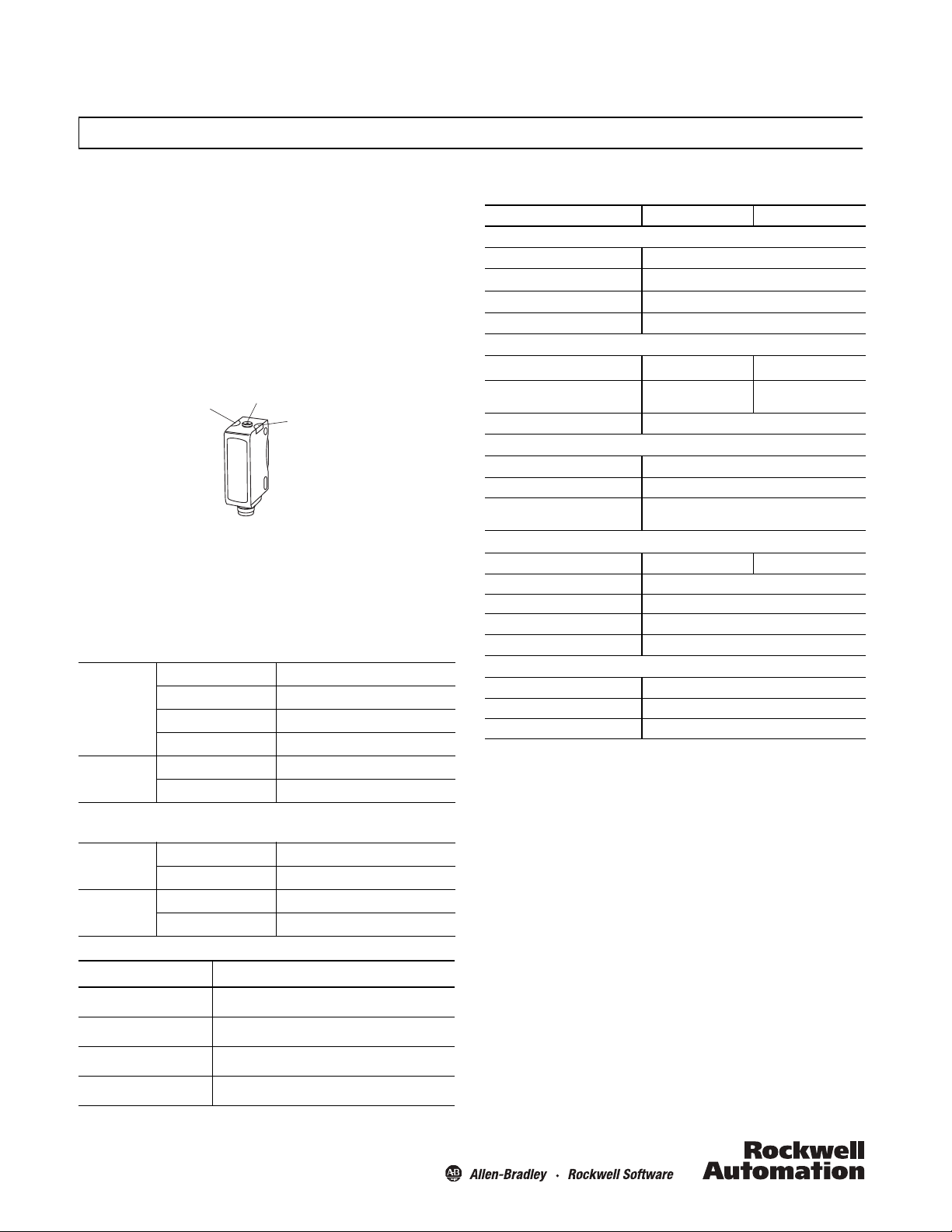
Yellow LED
Push button
Green LED
42JT VisiSight™ Photoelectric Diffuse Sensors with IO-Link
Default Settings:
The factory default settings are configured so that no teaching is
required for a vast majority of the applications.
Sensing Range: Maximum Setting
Output Mode: Light Operate (Output ON when target is
detected)
Output Type: Auto PNP/NPN or IO-Link. In Auto PNP/NPN mode,
the sensor continuously monitors the load connection and
automatically configures the output to PNP or NPN.
Sensor User Interface
LED Status
The table below provides LED status in the RUN mode, during
operation. The sensor is always in RUN mode, except when being
taught.
Auto PNP/NPN Operation
OFF Power is OFF
Green
Yel lo w
IO-Link Operation
Green
Yel lo w
Connection Types
Cat. No. Suffix Description
-A2 2 m cable
-P4 Integral 4-pin pico (M8) QD
-F4 4-pin DC micro (M12) QD on 150 mm (6in.) pigtail
ON Power is ON
Flashing (6 Hz) Unstable light level (0.5 < margin < 2)
Flashing (1.5 Hz) Output short circuit protection active
OFF Output de-energized
ON Output energized
OFF Power is OFF
Flashing (1 Hz) Power is ON
OFF Output de-energized
ON Output energized
General Specifications
42JT-D2LAT1- 42JT-D8LAT1-
Environmental
Certifications cULus and CE Marked for all applicable directives
Operating Environment
Operating Temperature [C (F)]
Storage Temperature [C (F)] -20…+80° (-4…+179°)
Optical
Light Source Visible red 660 nm Class 1 laser 650 nm
Sensing Range
Adjustments Push button
Electrical
Volta ge
Current Consumption 30 mA max.
Sensor Protection
Outputs
Response Time 0.5 ms max. 0.33 ms max.
Output Type Auto NPN or PNP
Output Function Selectable light operate or dark operate
Output Current 100 mA max.
Output Leakage Current 10 μA max.
Mechanical
Housing Material ABS
Lens Material PMMA
Cover Material PMMA
see Connection Types table
ECOLAB on P4 and A2 models only.
UL: -20…+50°C (-4…122°F)
UL: Class 2 source
IP67, IP69K, ECOLAB
-20…+60° (-4…+140°)
3…800 mm
(0.12…31.5 in.)
10…30V DC
Reverse polarity, short circuit, overload
protection
1…250 mm
(0.04…9.8 in.)
Mounting the Sensor
Securely mount the sensor on a firm, stable surface or support.
An application which is subject to excessive vibration or shifting
may cause intermittent operation. For installation convenience,
Rockwell Automation offers a wide range of mounting brackets
(see the Accessories section for more details).
Alignment Indication
For short range applications the visible light beam of the sensor
suffices as alignment aid.
The alignment feature may be used for longer range applications.
Alignment of the sensor is indicated via change in intensity of the
green LED in the Alignment Mode, as follows:
-Y4 4-pin pico (M8) QD on 150 mm (6in.) pigtail
Page 2
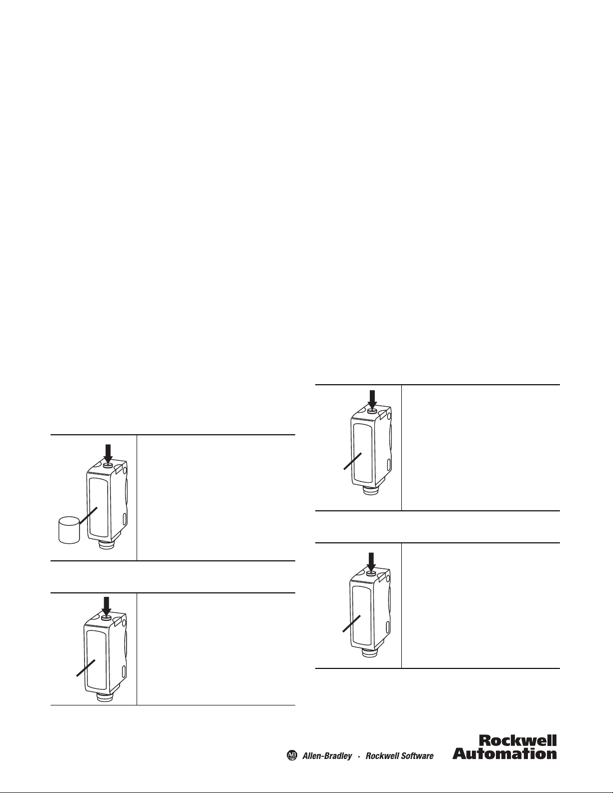
1. Press and release the push button twice within three seconds.
t > 3 s
Tar ge t
t < 0.5 s
t > 6 s
t < 0.5 s
After three seconds, the green LED turns OFF for 0.5 second
indicating the sensor is in the alignment mode.
2. Align sensor to the target to be detected. Intensity of green
LED increases with better alignment. Secure it in a position that
yields the highest intensity of the green LED. Press and release
the button once to return to the RUN mode, or the sensor
automatically returns to RUN mode in two minutes.
VisiSight™ Configuration
The 42JT VisiSight is configured using the push button or Remote
Teach or IO-Link and the LED indicators on the sensor. Five
features may be configured:
• Static Teach: Standard or precision teach for sensitivity/
sensing range
• Dynamic Teach (running process)
• Light operate (LO) or dark operate (DO) output
• Auto PNP/NPN, dedicated NPN or dedicated PNP
• Push button lock/unlock
The sensor output is disabled during Teach.
Teach Sensitivity/Sensing Range
The default setting is the maximum sensitivity/range.
Static Teach:
Teaching the sensitivity/sensing range is a two step process: teach
“target” (1st condition) and teach “no target” (2nd condition).
Switching threshold for output ON vs. OFF is set in between the
two conditions.
Note: The sensor can also be taught by teaching “no target” as
the first condition and “target” as the second condition.
Precision Teach: If there is nothing in the field of view in step
two, the sensing range will be set farther than the target to
maximize excess gain and improve detection reliability. For a
more precise setting with less excess gain, do not remove the
target in step two (i.e. the target is present for both step one and
step two). Also use precision teach for contrast applications.
Restore to factory default setting of maximum range: Perform
steps one and two with “no target” in the sensor’s field of view.
Dynamic Teach (Running Process):
If the targets to be detected are moving with the sensor aimed at
the running process, press and hold the button for three seconds
until the yellow LED starts flashing. The sensitivity will
automatically be taught in the next 30 seconds provided the
sensor sees two cycles of “target” and “no target.” The switching
threshold for output ON vs. OFF is set in between the two
conditions.
Teach Light Operate (L.O.) or Dark Operate (D.O.)
The default setting of the output is light operate (L.O.)
The L.O. setting means that output turns ON when the target is
detected. If the application requires the output to turn OFF when
the target is detected, the setting may be changed to dark
operate (D.O.).
1. To access the teach output mode setting:
Standard Teach:
1. To teach the “target” (first condition):
Place the target at the desired maximum distance.
Press and hold the button for three seconds until the
yellow LED starts flashing. Release the button. The
first condition has now been taught.
2. Teach “no target” (second condition):
Remove the target. Press and release the button. The
teach process is complete.
If the push button is not pressed within 30 seconds,
the sensor exits teach mode a nd returns to RUN mode
without learning the new setting.
Press and hold button for six seconds until green LED
starts flashing. Release the button. The current setting
is indicated by the yellow LED:
L.O.: Yellow LED ON
D.O.: Yellow L ED OFF
2. To change the sensor output mode setting:
Press and release the button within ten seconds to
toggle from L.O. to D.O., the selection indicated by the
yellow LED.
The sensor retains the setting per the last button
depression and returns to the RUN mode ten seconds
after the last button is depressed.
2
Page 3

Output Type Selection:
M12 Male
M8 Male
Brown (1)
White (2)
Black (4)
Blue (3)
+V
Remote Teach/Lock
Output: Auto PNP/NPN or IO-Link
-V
12
(0.47)
34
(1.34)
22.9
(0.90)
25.4
(1.0)
2.6
(0.10)
20
(0.79)
2.8
(0.11)
Clearance for
M3 or #4-40 screw
(2 places)
12
(0.47)
M8 x 1
34
(1.34)
22.9
(0.90)
25.4
(1.0)
2.6
(0.10)
20
(0.79)
Clearance for
M3 or #4-40 screw
(2 places)
Auto PNP/NPN, Dedicated NPN, Dedicated PNP
The default setting is Auto PNP/NPN. This means the sensor
monitors the load connection and automatically configures for
the proper operation, i.e., PNP or NPN. If no load is connected, the
sensor defaults to PNP.
The following applications are covered with dedicated PNP or
dedicated NPN selection:
a. Parallel wiring of multiple sensor outputs: select dedicated
PNP or dedicated NPN setting, as needed.
b. If the load is connected for NPN configuration but to a
different power supply than the power to the sensor or via a
load enabling contact (e.g., a relay contact in series with the
load): select dedicated NPN.
Selection can be made as follows:
1. To access output type: Press and hold the push button for 12
seconds (until both LEDs start flashing synchronously). At the
release of the button, the current setting of output type is
indicated by the slow flashing of the LED (or LEDs) as follows:
• Auto PNP/NPN: both LEDs flashing
• Dedicated NPN: green LED flashing
• Dedicated PNP: yellow LED flashing
2. To change output type: Press and release the push button
within ten seconds to select desired type. Each press of the
button will cycle to the next output setting. The type selected
is indicated by the LEDs. The sensor retains the setting per the
last button depression and returns to the RUN mode ten
seconds after the last button is pressed.
IO-Link
See instructions for IO-Link on www.ab.com. Remote Teach (pin 2)
is disabled in IO-Link operation. If output is selected as dedicated
NPN, IO-Link communication is unavailable.
Wiring Diagrams
The quick-disconnect connector is shown in the following
diagrams. The pin numbers correspond to male connectors on
the sensor.
Micro (M12) Male QD on Pigtail and
Integral Pico (M8) Male QD
1
2
Output Wiring
Normal operation: No connection. Disabled in IO-Link operation.
Remote Teach: Refer to the Remote Teach section.
Push Button Lock: Connect to -V. See the Push button Lock/Unlock
section.
4
2
1
3
4
3
Push Button Lock/Unlock
The push button or remote teach (RT) can be used to prevent
unauthorized users from changing teach settings.
To lock the push button: press and release the button three
times within three seconds. Both LEDs flash synchronously for
three seconds indicating that the push button is now locked.
To unlock the push button: press and release the button three
times within three seconds. Both LEDs flash asynchronously for
three seconds indicating that the push button is now unlocked.
Permanent lock: The push button may be permanently locked by
connecting the white wire (pin 2) to –V.
Remote Teach (RT)
The sensor can be taught remotely via the white wire (pin 2).
Connection to +V acts the same as the button being pressed and
no connection is the same as the button not being pressed. The
sensor can be taught by following the same teach/timing
sequence as used in the push button teach (e.g., connect to the
+V for more than three seconds to teach the “target,” disconnect
from the +V; remove the target and connect to the +V for less
than one second to teach the “no target” condition. All push
button functions can also be carried out via RT.
Approximate Dimensions [mm (in.)]
3
Page 4

Power, Control and Information Solutions Headquarters
Americas: Rockwell Automation, 1201 South Second Street, Milwaukee, WI 53204-2496 USA, Tel: (1) 414.382.2000, Fax: (1) 414.382.4444
Europe/Middle East/Africa: Rockwell Automation NV, Pegasus Park, De Kleetlaan 12a, 1831 Diegem, Belgium, Tel: (32) 2 663 0600, Fax: (32) 2 663 0640
Asia Pacic: Rockwell Automation, Level 14, Core F, Cyberport 3, 100 Cyberport Road, Hong Kong, Tel : (852) 2887 4788, Fax: (852) 2508 1846
www.rockwel lautomation.com
Accessories
30°
20°
63.5
(2.5)
8
(0.32)
14
(0.55)
R 25.4
(1.0)
12
(0.47)
18.6
(0.73)
33
(1.3)
10°
1000
100
1
10
10
(0.4)
800
(31.5)
600
(23.6)
400
(15.75)
200
(7.87)
Distance [mm (in.)]
Excess Gain
Distance [mm (in.)]
Size [mm]
Distance [mm (in.)]
Excess Gain
0
0.0
0.5
1.0
1.5
2.0
horizontal = vertical
200
(7.87)
150
(5.91)
100
(3.94)
50
(1.96)
250
(9.84)
Distance [mm (in.)]
Size [mm]
Stainless Steel Mounting Brackets
1) 60-BJS-L1
°
15
12
(0.47)
Spot Size (800 mm)
70
60
horizontal = verticalhorizontal = verticalhorizontal = verticalhorizontal = verticalhorizontal = verticalhorizontal = verticalhorizontal = verticalhorizontal = verticalhorizontal = verticalhorizontal = verticalhorizontal = verticalhorizontal = verticalhorizontal = verticalhorizontal = vertical
50
40
18.6
(0.73)
33
(1.3)
R 25.4
8 (0.32)
24
(0.95)
(R 1.0)
14
(0.55)
2) 60-BJT-L2
3) 60-2619 VisiSight-compatible swivel/tilt mounting bracket
Typical Response Curves
Standard Diffuse (800 mm)
30
20
10
0
0
200
(7.87)
Laser Diffuse (250 mm)
30
25
20
15
10
5
0
0
50
(1.96)
Laser Spot Size (250 mm)
100
(3.94)
400
(15.75)
150
(5.91)
600
(23.6)
200
(7.87)
800
(31.5)
250
(9.84)
Rockwell Automation maintains current product environmental information on its website at
http//www.rockwellautomation.com/rockwellautomation/about-us/sustainability-ethics/product-environmental-compliance.page.
The spot size is square in shape with one side dimension per the graph.
10000205876 Ver 03
Printed in Germany
May 2014
068-14545
 Loading...