

Page 1

Installation Instructions
Mounting Levers
for PanelView Plus 400 and 600 Terminals
Catalog Number 2711P-RTFC
Inside...
English...................................................3
Français.................................................5
Deutsch .................................................7
Español..................................................9
Italiano ................................................11
Português............................................13
Publication 2711P-IN016A-MU-P
Page 2
2 Mounting Levers
Important User Information
Because of the variety of uses for the products described in this publication, those responsible for the
application and use of these products must satisfy themselves that all necessary steps have been taken to
assure that each application and use meets all performance and safety requirements, including any applicable
laws, regulations, codes and standards. In no event will Rockwell Automation be responsible or liable for
indirect or consequential damage resulting from the use or application of these products.
Any illustrations, charts, sample programs, and layout examples shown in this publication are intended solely
for purposes of example. Since there are many variables and requirements associated with any particular
installation, Rockwell Automation does not assume responsibility or liability (to include intellectual property
liability) for actual use based upon the examples shown in this publication.
Allen-Bradley publication SGI-1.1, Safety Guidelines for the Application, Installation and Maintenance of
Solid-State Control (available from your local Rockwell Automation office), describes some important
differences between solid-state equipment and electromechanical devices that should be taken into
consideration when applying products such as those described in this publication.
Reproduction of the contents of this copyrighted publication, in whole or part, without written permission of
Rockwell Automation, is prohibited.
Throughout this publication, notes may be used to make you aware of safety considerations. The following
annotations and their accompanying statements help you to identify a potential hazard, avoid a potential
hazard, and recognize the consequences of a potential hazard:
WARNING
Identifies information about practices or circumstances that can cause an explosion in a
hazardous environment, which may lead to personal injury or death, property damage,
or economic loss.
!
ATTENTION
Identifies information about practices or circumstances that can lead to personal injury
or death, property damage, or economic loss.
!
IMPORTANT
Publication 2711P-IN016A-MU-P
Identifies information that is critical for successful application and understanding of the
product.
Page 3
Installation Instructions
Mounting Levers
for PanelView Plus 400 and 600 Terminals
Catalog Number 2711P-RTFC
English
This document provides instructions on how to install the PanelView Plus 400 and
600 Terminals in a panel or enclosure using the 2711P-RTFC mounting levers. Eight
mounting levers are provided with kit.
The mounting levers hold the terminal tightly against the mounting enclosure. The
number of levers used for installation varies for each device.
Number of Levers Device Clip Location
4 PanelView Plus 400 Keypad
PanelView Plus 600 Touch
6 PanelView Plus 600 Keypad or
Keypad/Touch
Top: Left and Right
Bottom. Left and Right
Top: Left, Middle and Right
Bottom: Left, Middle and Right
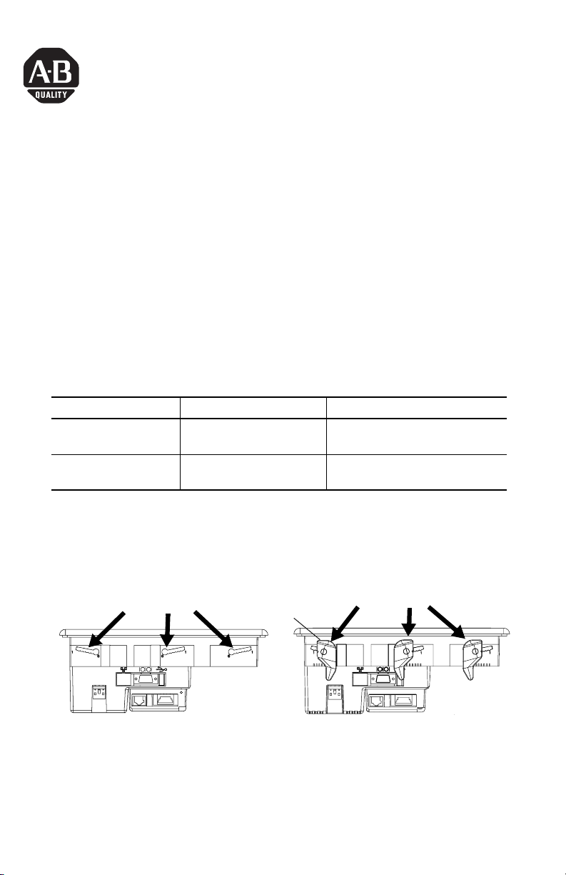
To install the mounting levers:
1. Insert all mounting levers (4 or 6) into the mounting slots of the terminal (as
shown below). Slide each lever until flat side of lever touches the surface of
the panel.
Mounting Slots
2. When all levers are in place, slide each lever an additional notch or two
until you hear a click.
Flat Side of Lever
Mounting Lever
Publication 2711P-IN016A-MU-P
Page 4
4 Mounting Levers
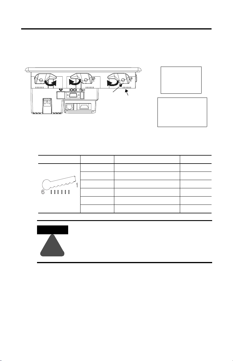
3. Rotate each lever in the direction indicated until lever is in final latch
position. Follow the latching sequence below to obtain optimum terminal fit.
14
4 Levers
1
6
Notch
Alignment Marks
Rotate until notch in levers
align with proper alignment
mark on terminal.
3
6 Levers
2
513
246
Use the table below as a guide to insure an adequate gasket seal between
terminal and panel.
Lever Position Panel Thickness Range Typical Gauge
1 0.15 - 2.01 mm (0.060 - 0.079 in) 16
2 2.03 - 2.64 mm (0.08 - 0.104 in) 14
3 2.67 - 3.15 mm (0.105 - 0.124 in) 12
4 3.17 - 3.66 mm (0.125 - 0.144 in) 10
5 3.68 - 4.16 mm (0.145 - 0.164 in) 8/9
6 4.19 - 4.75 mm (0.165 - 0.187 in) 7
Follow instructions above to provide a proper seal and
to prevent potential damage to the terminal.
3
4
5
6
Terminal Markings
for Alignment
ATTENTION
1
2
Allen-Bradley assumes no responsibility for water or
chemical damage to the terminal or other equipment
!
within the enclosure because of improper installation.
Publication 2711P-IN016A-MU-P
Page 5
Notice d'installation
Attaches de fixation
pour terminaux PanelView Plus 400 et 600
Référence 2711P-RTFC
Français
Le présent document indique comment installer les terminaux PanelView Plus 400
et 600 sur un panneau ou dans une armoire à l’aide des attaches de
fixation 2711P-RTFC. Le kit contient huit attaches de fixation.
Les attaches de fixation maintiennent fermement le terminal contre le support de
montage. Le nombre d’attaches utilisées pour l’installation varie d’un terminal à
l'autre.
Nombre d’attaches Terminal Emplacement de l’attache
4 PanelView Plus 400 à clavier
PanelView Plus 600 à dalle tactile
6 PanelView Plus 600 à clavier
ou à clavier et dalle tactile
Au-dessus : à gauche et à droite
Au-dessous : à gauche et à droite
Au-dessus : à gauche, au milieu et à droite
Au-dessous : à gauche, au milieu et à droite
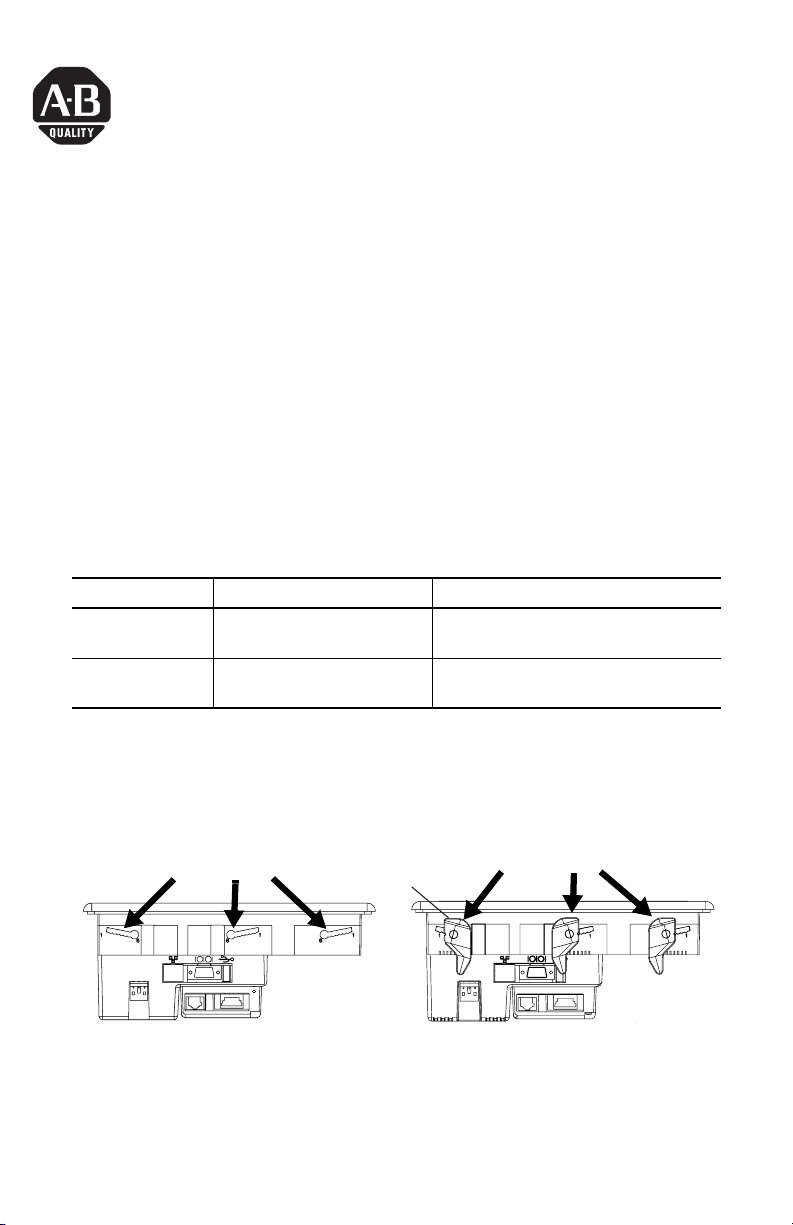
Pour installer les attaches de fixation :
1. Introduisez toutes les attaches de fixation (4 ou 6) dans les encoches situées
sur le terminal (comme illustré ci-dessous) et faites-les glisser jusqu’à que la
partie plate des attaches soit en contact avec la surface du panneau.
Encoches de fixation
2. Une fois toutes les attaches en place, faites-les glisser d’un ou deux crans
supplémentaires jusqu’à ce que vous entendiez un déclic.
Partie plate de l’attache
Attaches de fixation
Publication 2711P-IN016A-MU-P
Page 6

6 Attaches de fixation
3. Faites-les ensuite pivoter dans la direction indiquée jusqu'à ce qu’elles soient
verrouillées. Suivez la séquence de verrouillage ci-dessous afin que votre
terminal soit maintenu le mieux possible.
14
4 attaches
1
Encoche
Faites pivoter l’attache
jusqu’à ce que la petite
encoche située sur l’attache
soit en face du repère
d’alignement qui convient sur
le terminal.
6
Repères d’alignement
Aidez-vous du tableau suivant pour assurer une bonne étanchéité du joint
entre le terminal et le panneau.
Position de l’attache Epaisseur du panneau Calibre type
1 0,15 à 2,01 mm 16
1
2
3
4
5
6
Repères d’alignement
du terminal
2 2,03 à 2,64 mm 14
3 2,67 à 3,15 mm 12
4 3,17 à 3,66 mm 10
5 3,68 à 4,16 mm 8/9
6 4,19 à 4,75 mm 7
3
513
6 attaches
246
2
ATTENTION
!
Publication 2711P-IN016A-MU-P
Suivez les instructions ci-dessous pour assurer une
bonne étanchéité et éviter d’endommager le terminal.
Allen-Bradley ne saurait être tenu pour responsable des
dégâts causés par une infiltration d’eau ou de produit
chimique dans le terminal ou dans tout autre
équipement présent dans l’armoire, suite à une
installation incorrecte.
Page 7

Installationsanleitung
Montagehebel
für Terminals des Typs PanelView Plus 400 und 600
Bestellnummer 2711P-RTFC
Deutsch
Das vorliegende Dokument enthält eine Anleitung zur Montage der Terminals
PanelView Plus 400 und 600 in einem Schaltschrank oder Gehäuse mithilfe der
Montagehebel 2711P-RTFC. Acht Montagehebel sind im Lieferumfang enthalten.
Die Montagehebel drücken das Terminal eng gegen die Montageplatte. Die Anzahl
der für die Installation benötigten Hebel ist je nach Gerät unterschiedlich.
Benötigte Hebel Gerät Klammerposition
4 PanelView Plus 400 mit Tastatur
PanelView Plus 600 mit
Touchscreen
6 PanelView Plus 600 mit Tastatur
oder Tastatur & Touchscreen
So installieren Sie die Montagehebel:
Oben: Links und rechts
Unten: Links und rechts
Oben: Links, Mitte und rechts
Unten: Links, Mitte und rechts
1. Führen Sie alle vier bzw. sechs Montagehebel wie nachfolgend dargestellt in die
Montageschlitze des Terminals ein. Schieben Sie jeden Hebel so weit durch, bis
die flache Seite des Hebels die Oberfläche des Schaltschranks berührt.
Montageschlitze
2. Sobald sich alle Hebel in der richtigen Position befinden, schieben Sie jeden
Hebel noch ein Stück weiter, bis er hörbar einrastet.
Flache Seite des Hebels
Montagehebel
Publikation 2711P-IN016A-MU-P
Page 8

8 Montagehebel
3. Drehen Sie jeden Hebel so lange in die angegebene Richtung, bis er sich in der
endgültigen Verriegelungsposition befindet. Folgen Sie der nachfolgend dargestellten Verriegelungsreihenfolge, um einen optimalen Sitz des Terminals zu
erhalten.
14
4 Hebel
1
6
Kerbe
Ausrichtungs-
markierung
Drehen Sie so lange, bis die
Hebelkerbe der richtigen
Ausrichtungsmarkierung des
Terminals gegenüberliegt.
Verwenden Sie die in der Tabelle genannten Werte als Richtlinie, um eine
optimale Dichtung zwischen dem Terminal und dem Schaltschrank zu erzielen.
Hebelposition Schaltschrankdicke Typisches Gauge-Maß
1 0,15–2,01 mm 16
1
2
3
4
5
6
Ausrichtungsmarkierungen
am Terminal
ACHTUNG
!
Folgen Sie den Anleitungen oben, um eine optimale
Dichtung zu erzielen und so mögliche Beschädigungen
des Terminals zu vermeiden. Rockwell Automation
übernimmt keine Haftung für Schäden, die durch Wasser
oder Chemikalien am Terminal oder an anderen Geräten
innerhalb des Gehäuses entstehen und auf eine unsachgemäße Installation zurückzuführen sind.
2 2,03–2,64 mm 14
3 2,67–3,15 mm 12
4 3,17–3,66 mm 10
5 3,68–4,16 mm 8/9
6 4,19–4,75 mm 7
3
6 Hebel
2
513
246
Publikation 2711P-IN016A-MU-P
Page 9

Instrucciones de instalación
Palancas de montaje
para los terminales PanelView Plus 400 y 600
Número de catálogo 2711P-RTFC
Español
Este documento proporciona instrucciones para llevar a cabo la instalación de los
terminales PanelView Plus 400 y 600 en un panel o envolvente mediante las
palancas de montaje 2711P-RTFC. Este conjunto contiene ocho palancas de
montaje.
Las palancas de montaje sostienen firmemente al terminal en el envolvente de
montaje. El número de palancas utilizadas para la instalación varía para cada
dispositivo.
Número de palancas Dispositivo Ubicación del sujetador
4 Teclado PanelView Plus 400
Pantalla táctil PanelView Plus 600
6 Teclado o combinación de teclado y
pantalla táctil PanelView Plus 600
Superior: izquierda y derecha
Inferior: izquierda y derecha
Superior: izquierda, centro y derecha
Inferior: izquierda, centro y derecha
Instalación de las palancas de montaje:
1. Inserte todas las palancas de montaje (4 ó 6) en las ranuras de montaje del
terminal (como se muestra a continuación). Deslice cada palanca hasta que
el lado plano quede en contacto con la superficie del panel.
Ranuras de montaje
2. Una vez que las palancas están ubicadas, desplace cada una de ellas una o
dos muescas más hasta que escuche un clic.
Lado plano de la palanca
Palanca de montaje
Publicación 2711P-IN016A-MU-P
Page 10

10 Palancas de montaje
3. Gire cada palanca en la dirección indicada hasta que llegue a la posición de
enclavamiento final. Continúe con la secuencia de enclavamiento indicada a
continuación para obtener un ajuste del terminal óptimo.
14
4 palancas
1
Muesca
Gire hasta que la muesca de las
palancas esté alineada con la
marca de alineación del terminal.
6
Marcas de alineación
3
Utilice la siguiente tabla como referencia para asegurar un sello de
empaquetadura adecuado entre el terminal y el panel.
Posición de la palanca Rango del grosor del panel Medidor típico
1 0.15 a 2.01 mm (0.060 a 0.079 pulg.) 16
1
2
3
4
5
6
Marcas del terminal
para alineación
ATENCIÓN
2 2.03 a 2.64 mm (0.08 a 0.104 pulg.) 14
3 2.67 a 3.15 mm (0.105 a 0.124 pulg.) 12
4 3.17 a 3.66 mm (0.125 a 0.144 pulg.) 10
5 3.68 a 4.16 mm (0.145 a 0.164 pulg.) 8/9
6 4.19 a 4.75 mm (0.165 a 0.187 pulg.) 7
Siga las instrucciones previamente detalladas para
lograr un sellado adecuado y evitar un daño potencial
del terminal. Allen-Bradley no asumirá responsabilidad
alguna por daños ocasionados por agua o productos
!
químicos al terminal u otros equipos dentro del
envolvente debido a una instalación incorrecta.
2
513
6 palancas
246
Publicación 2711P-IN016A-MU-P
Page 11

Istruzioni per l'installazione
Levette di montaggio
per terminali PanelView Plus 400 e 600
Numero di catalogo 2711P-RTFC
Italiano
Questo documento descrive come installare i terminali PanelView Plus 400 e 600 su
un pannello o in una custodia utilizzando le levette di montaggio 2711P-RTFC. Il kit
contiene otto levette di montaggio.
Le levette servono per bloccare il terminale alla custodia di montaggio. Il numero di
levette utilizzate varia in base al tipo di dispositivo.
Numero di levette Dispositivo Posizioni
4 PanelView Plus 400 con tastiera
PanelView Plus 600 touchscreen
6 PanelView Plus 600 con tastiera
o tastiera/touchscreen
In alto: sinistra e destra
In basso: sinistra e destra
In alto: sinistra, in mezzo e destra
In basso: sinistra, in mezzo e destra
Per installare le levette di montaggio:
1. Inserire le levette di montaggio (4 o 6) nelle apposite fessure sul terminale
(come mostrato sotto). Fare scorrere ogni levetta finché il lato piatto tocca la
superficie del pannello.
Fessure di montaggio
2. Quando tutte le levette sono state inserite, spostarle di una o due tacche fino
a quando si sente un clic.
Lato piatto della levetta
Levetta di montaggio
Pubblicazione 2711P-IN016A-MU-P
Page 12

12 Levette di montaggio
3. Ruotare le levette nella direzione indicata fino a portarle nella posizione
finale di blocco. Attenersi alla sequenza di chiusura indicata sotto per
ottenere un blocco ottimale del terminale.
14
4 Levette
1
6
Tacca
Segni di allineamento
Ruotare fino a quando la tacca
delle levette risulta in linea
con il segno di allineamento
del terminale.
3
6 Levette
2
513
246
Usare la tabella sottostante come guida per garantire un'adeguata tenuta tra
terminale e pannello.
Posizione levetta Spessore pannello Calibro tipico
1 0,15 - 2,01 mm 16
2 2,03 - 2,64 mm 14
3 2,67 - 3,15 mm 12
4 3,17 - 3,66 mm 10
5 3,68 - 4,16 mm 8/9
6 4,19 - 4,75 mm 7
Attenersi alle istruzioni descritte sopra per ottenere una
tenuta corretta ed evitare potenziali danni al terminale.
3
4
5
6
Segni sul terminale
per l'allineamento
ATTENZIONE
1
2
Allen-Bradley non è responsabile per eventuali danni
causati al terminale o ad altre apparecchiature
!
all'interno della custodia, provocati da acqua o agenti
chimici e dovuti ad un'installazione errata.
Pubblicazione 2711P-IN016A-MU-P
Page 13

Instruções de Instalação
Alavancas de Fixação
para Terminais PanelView Plus 400 e 600
Código de Catálogo 2711P-RTFC
Português
Este documento fornece instruções para a instalação dos terminais PanelView Plus
400 e 600 em um painel ou gabinete usando as alavancas de fixação 2711P-RTFC.
Oito alavancas de fixação são fornecidas com o kit.
As alavancas de fixação prendem o terminal firmemente no gabinete de fixação. O
número de alavancas usadas para instalação varia para cada dispositivo.
Número de
Alavancas
4 PanelView Plus 400 com Teclado
6 PanelView Plus 600 com Teclado ou
Para instalar as alavancas de fixação:
1. Insira todas as alavancas de fixação (4 ou 6) nas ranhuras de fixação do
terminal (conforme mostrado abaixo). Faça deslizar cada alavanca até que a
lateral plana encoste na superfície do painel.
Dispositivo Local de Fixação
Parte Superior: Esquerda e Direita
PanelView Plus 600 com Touch Screen
Teclado/Touch Screen
Parte Inferior. Esquerda e Direita
Parte Superior: Esquerda, Centro e
Direita
Parte Inferior: Esquerda, Centro e Direita
Slots de Fixação
2. Quando todas as alavancas estiverem na posição adequada, faça cada uma
delas deslizar por mais um entalhe ou dois até que você ouça um clique.
Lateral Plana da Alavanca
Alavanca de Fixação
Publicação 2711P-IN016A-MU-P
Page 14

14 Alavancas de Fixação
3. Gire cada alavanca no sentido indicado até chegar à posição final de
travamento. Siga a seqüência de travamento abaixo para obter o encaixe
perfeito do terminal.
14
4 Alavancas
1
Entalhe
Gire até que o entalhe das
alavancas esteja alinhado com a
marca de alinhamento correta do
terminal.
6
Marcas de Alinhamento
3
6 Alavancas
2
513
246
Use a tabela abaixo como guia para garantir a vedação adequada da junção
entre o terminal e o painel.
Posição da Alavanca Faixa de Espessura do Painel Bitola Típica
1 0,15 a 2,01 mm (0,060 a 0,079 pol) 16
2
3
4
5
6
Marcações do
Terminal
ATENÇÃO
1
2 2,03 a 2,64 mm (0,08 a 0,104 pol) 14
3 2,67 a 3,15 mm (0,105 a 0,124 pol) 12
4 3,17 a 3,66 mm (0,125 a 0,144 pol) 10
5 3,68 a 4,16 mm (0,145 a 0,164 pol) 8/9
6 4,19 a 4,75 mm (0,165 a 0,187 pol) 7
Siga as instruções acima para obter uma vedação
perfeita e impedir possíveis danos ao terminal. A
Allen-Bradley não se responsabiliza por danos
causados por água ou produtos químicos ao terminal
!
ou outro equipamento dentro do gabinete devido à
instalação incorreta.
Publicação 2711P-IN016A-MU-P
Page 15

15
Publication 2711P-IN016A-MU-P
Page 16

Publication 2711P-IN016A-MU-P - August 2003 PN 41061-321-01(1)
Copyright © 2003 Rockw ell Automation, Inc. All rights reserved. Printed in the U.S.A.
 Loading...