

Page 1
Installation Instructions
AC Power Supply
for PanelView Plus/PanelView Plus CE Terminals
Catalog Number 2711P-RSACDIN
Topic Page
Important User Information 2
Environment and Enclosure 3
Hazardous Locations 4
Overview 5
Install the Power Supply 6
Wire the Power Supply 7
Mounting Dimensions 8
Diagnostic Indicator 9
Specifications 9
Additional Resources 11
Publication 2711P-IN005C-EN-P - March 2007
Page 2
2 AC Power Supply for PanelView Plus/PanelView Plus CE Terminals
Important User Information
Solid state equipment has operational characteristics differing from those of electromechanical equipment.
Safety Guidelines for the Application, Installation and Maintenance of Solid State Controls (publication
SGI-1.1 available from your local Rockwell Automation sales office or online at
http://literature.rockwellautomation.com
equipment and hard-wired electromechanical devices. Because of this difference, and also because of the
wide variety of uses for solid state equipment, all persons responsible for applying this equipment must
satisfy themselves that each intended application of this equipment is acceptable.
In no event will Rockwell Automation, Inc. be responsible or liable for indirect or consequential damages
resulting from the use or application of this equipment.
The examples and diagrams in this manual are included solely for illustrative purposes. Because of the many
variables and requirements associated with any particular installation, Rockwell Automation, Inc. cannot
assume responsibility or liability for actual use based on the examples and diagrams.
No patent liability is assumed by Rockwell Automation, Inc. with respect to use of information, circuits,
equipment, or software described in this manual.
Reproduction of the contents of this manual, in whole or in part, without written permission of Rockwell
Automation, Inc., is prohibited.
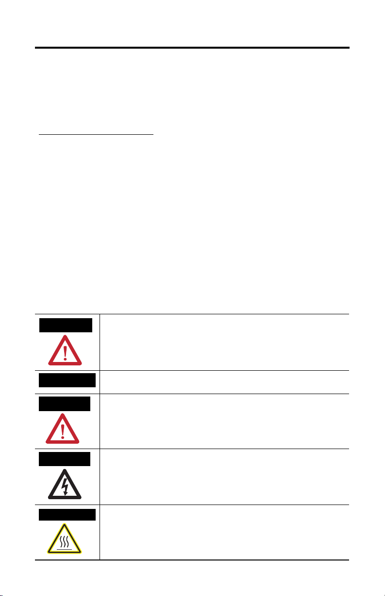
Throughout this manual, when necessary, we use notes to make you aware of safety considerations.
) describes some important differences between solid state
WARNING
IMPORTANT
ATTENTION
SHOCK HAZARD
BURN HAZARD
Identifies information about practices or circumstances that can cause an explosion in
a hazardous environment, which may lead to personal injury or death, property
damage, or economic loss.
Identifies information that is critical for successful application and understanding of
the product.
Identifies information about practices or circumstances that can lead to personal injury
or death, property damage, or economic loss. Attentions help you to identify a hazard,
avoid a hazard, and recognize the consequences.
Labels may be located on or inside the equipment, for example, a drive or motor, to
alert people that dangerous voltage may be present.
Labels may be located on or inside the equipment, for example, a drive or motor, to
alert people that surfaces may be dangerous temperatures.
Publication 2711P-IN005C-EN-P - March 2007
Page 3

AC Power Supply for PanelView Plus/PanelView Plus CE Terminals 3
Environment and Enclosure
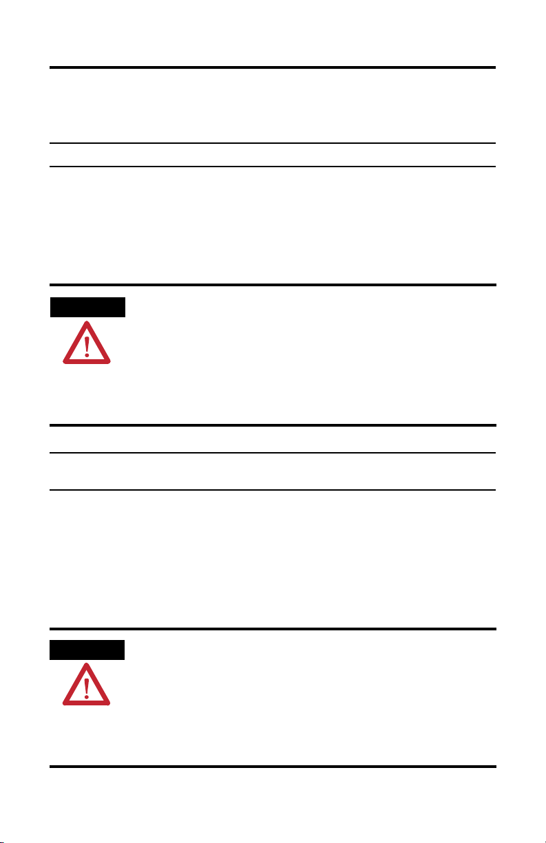
ATTENTION
Environment and Enclosure
This equipment is intended for use in a Pollution Degree 2 industrial
environment, in overvoltage Category II applications (as defined in IEC
publication 60664-1), at altitudes up to 2000 meters without derating.
This equipment is considered Group 1, Class A industrial equipment
according to IEC/CISPR Publication 11. Without appropriate precautions,
there may be potential difficulties ensuring electromagnetic compatibility
in other environments due to conducted as well as radiated disturbance.
This equipment is supplied as open type equipment. It must be mounted
within an enclosure that is suitably designed for those specific
environmental conditions that will be present, and appropriately designed
to prevent personal injury resulting from accessibility to live parts. The
interior of the enclosure must be accessible only by the use of a tool.
Subsequent sections of this publication may contain additional information
regarding specific enclosure type ratings that are required to comply with
certain product safety certifications.
See NEMA Standards publication 250 and IEC publication 60529, as
applicable, for explanations of the degrees of protection provided by
different types of enclosures. Also, see the appropriate sections in this
publication, as well as the Allen-Bradley publication 1770-4.1, Industrial
Automation Wiring and Grounding Guidelines, for additional installation
requirements pertaining to this equipment.
Publication 2711P-IN005C-EN-P - March 2007
Page 4
4 AC Power Supply for PanelView Plus/PanelView Plus CE Terminals
Hazardous Locations
The following information applies when operating this equipment in hazardous locations:
Products are suitable for use in Class 1, Div 2 Groups A, B, C, and D Hazardous Locations and nonhazardous
location only. Each product is supplied with markings on the rating nameplate indicating the hazardous
location temperature code. When combining products within a system, the most adverse temperature code
(lowest "T" number) may be used to help determine the overall temperature code of the system. Combinations
of equipment in your system are subject to investigation by the local authority having jurisdiction at the time
of installation.
WARNING
Les informations suivantes concernent l’utilisation de cet équipement en environnement
dangereux :
EXPLOSION HAZARD
• Substitution of components may impair suitability for Class I, Division 2.
• Do not replace components or disconnect equipment unless power has been switched
off or the area is known to be nonhazardous.
• Do not connect or disconnect components unless power has been switched off or the
area is known to be nonhazardous.
• This product must be installed in an enclosure.
• All wiring must comply with N.E.C. article 501-4(b).
Cet équipement est conçu pour être utilisé dans des environnements de Classe I, Division 2,
Groupes A, B, C et D dangereux et non dangereux. Chaque produit est livré avec des
marquages sur sa plaque d’identification qui indiquent le code de température pour les
environnements dangereux. Lorsque plusieurs produits sont combinés dans un système,
utiliser le code de température le plus défavorable (code de température le plus faible) pour
déterminer le code de température global du système. Les combinaisons d’équipements dans
votre système sont sujettes à inspection par les autorités locales compétentes au moment de
l’installation.
AVERTISSEMENT
DANGER D’EXPLOSION
• La substitution de composants peut rendre cet équipement impropre à une utilisation en
environnement de Classe 1, Division 2.
• Ne pas remplacer de composants ou déconnecter l'équipement sans s'être assuré que
l'alimentation est coupée et que l'environnement est classé non dangereux.
• Ne pas connecter ou déconnecter des composants sans s'être assuré que l'alimentation
est coupée ou que l'environnement est classé non dangereux.
• Ce produit doit être installé dans une armoire.
Publication 2711P-IN005C-EN-P - March 2007
Page 5

Overview
AC Power Supply for PanelView Plus/PanelView Plus CE Terminals 5
1
2
POWER
3
4
5
Item Description
1 Power Supply module 2711P-RSACDIN
2 Indicator
3 120/230V ac ground
4 120/230V ac common L2/N connections
5 120/230V ac power L1 connections
6 +24V dc connections
7 24V common connections
ATTENTION
The 2711P-RSACDIN power supply provides sufficient 24V dc power to a single
PanelView Plus or PanelView Plus CE.
PanelView P
POW
ER SUPPLY
2711P-RSACDIN
lus
24 VDC
7
6
Publication 2711P-IN005C-EN-P - March 2007
Page 6

6 AC Power Supply for PanelView Plus/PanelView Plus CE Terminals
Install the Power Supply
WARNING
If you connect or disconnect wiring while the field side power is on, an electrical arc can
occur. This could cause an explosion in hazardous installations. Be sure that power is removed or the area is nonhazardous before proceeding.
A
POWER
PanelView Plus
24 VDC
POW
ER SUPPLY
2711P-RSACDIN
B
POWER
POWER SUPPLY
2711P-RSACDIN
24 VDC
C
C
1. Position the power supply module A on a 35 x 7.5 mm DIN rail B (A-B pt.
no. 199-DR1) at 30° angle.
The power supply must be mounted horizontally as shown.
2. Rotate the power supply module onto the DIN rail with the top of the rail
hooked under the lip on the rear of the power supply.
3. Press the power supply module down onto the DIN rail until flush.
Locking tab (C) will snap into position and lock the power supply to the
DIN rail.
4. If the power supply module does not lock in place, use a screwdriver or
similar device to move the locking tab down while pressing the power
supply flush onto the DIN rail and release the locking tab to lock the power
supply in place.
If necessary, push up on the locking tab to lock.
5. Connect the power supply wiring as shown under Wire the Power Supply.
Publication 2711P-IN005C-EN-P - March 2007
Page 7

AC Power Supply for PanelView Plus/PanelView Plus CE Terminals 7
Wire the Power Supply
PanelView Plus
POWER SUPPLY
2711P-RSACDIN
COM
24V
24V DC
H
I
J
POWER
(GR) A
(L2/N) B
(L1) C
FGED
IMPORTANT
Input and output wiring must be in accordance with Class I, Division 2 wiring
methods per Article 501-4(b) of the National Electrical Code and in accordance
with the authority having jurisdiction.
Terminals A, B and C are 120/230V supply terminals. Terminals D, E and F are
available to daisychain this 120/230V power to other 2711P-RSACDIN power
supplies.
Torque screw terminals to 5-7 lb-in (0.5 - 0.6 Nm) when making connections.
1. Connect the 120/230V ac power to the left side terminals on the connectors
on the left side of the module as follows:
Connect To
ac Ground GR A
120/230V ac common L2/N B
120/230V ac power L1 C
ATTENTION
The total length of wire for terminals H, I, J and G must not exceed 3 m.
Exceeding the 3 m length can reduce noise immunity.
2. Connect terminal G or J (+24V dc) to the +24V dc terminal on the PanelView
Plus/PanelView Plus CE.
3. Connect terminal H or I (+24V dc common) to the +24V dc common
terminal on the PanelView Plus/PanelView Plus CE.
The remaining two 24V terminals should remain unconnected.
Publication 2711P-IN005C-EN-P - March 2007
Page 8

8 AC Power Supply for PanelView Plus/PanelView Plus CE Terminals
2.0
(50)
1.2
(28)
3.7
(94)
2711P-RSACDIN
3.2
(80)
3.4
(87)
Mounting Dimensions
Inches
(Millimeters)
PanelView Plus
POWER SUPPLY
2711P-RSACDIN
COM
24V
24V DC
B
POWER
A
3.4H x 3.7W x 2.7D
(87H x 95W x 69D)
A = DIN rail
B = Secure DIN rail approximately every 200mm
Publication 2711P-IN005C-EN-P - March 2007
Page 9

AC Power Supply for PanelView Plus/PanelView Plus CE Terminals 9
Diagnostic Indicator
The power supply has one indicator.
PanelView Plus
Power
POWER
24V DC
POWER SUPPLY
2711P-RSACDIN
Indicator
COM
24V
The power indicator is on (green) when voltage at the output
is between 20.4 V dc and 28V dc.
Indicator Description
ON (green) Output voltage is greater than 20.4V dc, but less than 28V dc
OFF No power applied to power supply.
Output voltage exceeded 35V dc, and overvoltage protection
shut down unit.
Output current is above 3 A.
Specifications
Input Specifications
Nominal Supply Voltage 120V ac, 47…63Hz; 1.7 A maximum
230V ac, 47…63 Hz; 1.1 A maximum
Voltage Range 85…265V ac
Inrush Current 40 A typical, 1 ac cycle @ V
Interruption Output voltage will stay within specification when input drops out
for 1/2 cycle @ 47 Hz, 85V ac with maximum load
Output Specifications
Nominal Output Voltage +24V dc SELV
Voltage Range 20.4…27.6V dc (includes noise and 5% ac ripple)
265V ac, 55°C
in
Publication 2711P-IN005C-EN-P - March 2007
Page 10

10 AC Power Supply for PanelView Plus/PanelView Plus CE Terminals
Output Current 3 A maximum horizontal mount
Minimum Load 50 mA
Overvoltage Protection Output internally limited to 35V dc. Cycle power to reenergize.
Overcurrent Protection Current limit 3.2 A minimum (107% minimum)
Leakage Current 0.5 mA rms maximum @ rated input and output
Isolation Voltage 2830V dc for 1 second
General Specifications
Mounting Horizontal on a DIN rail.
Wall or panel mount with 1794-NM1 panel mounting kit
Terminal Screw Torque 5-7 lb-in (0.5…0.6 Nm)
Dimensions, HxWxD 3.4 x 2.7 x 2.7 in.
87 x 68 x 69 mm
Environmental Specifications
Operating Temperature IEC 60068-2-1 (Test Ad, Operating Cold)
Storage Temperature IEC 60068-2-1 (Test Ab, Unpackaged, Nonoperating Cold)
Relative Humidity IEC 60068-2-30 (Test Db, Unpackaged, Nonoperating Damp Heat)
Shock
Operating
Non Operating
Vibration IEC 60068-2-6 (Test Fc, Operating)
ESD Immunity IEC 61000-4-2
Radiated RF Immunity IEC 61000-4-3
EFT/B Immunity IEC 61000-4-4
Surge Transient Immunity IEC 61000-4-5
IEC 60068-2-2 (Test Bd, Operating Dry Heat)
IEC 60068-2-14 (Test Nb, Operating Thermal Shock)
32…131 °F (0…55°C)
IEC 60068-2-2 (Test Bb, Unpackaged, Nonoperating Dry Heat)
IEC 60068-2-14 (Test Na, Unpackaged, Nonoperating Thermal Shock)
-40…185°F (-40…85 °C)
5…95%, noncondensing
IEC 60068-2-27 (Test Ea, Unpackaged Shock)
30g
50g
5g @ 10…500 Hz
4 kV contact discharges
8 kV air discharges
10V/m with 1 kHz sine-wave 80% AM from 30…1000 MHz
±2 kV @ 5 kHz on power ports
±1 kV line-line (DM) and ±2 kV line-earth (CM) on ac power ports
Publication 2711P-IN005C-EN-P - March 2007
Page 11

AC Power Supply for PanelView Plus/PanelView Plus CE Terminals 11
Conducted RF Immunity IEC 61000-4-6
10V rms with 1kHz sine wave 80% AM from 150 kHz to 80 MHz
Emissions CISPR 11
Group 1, Class A (with appropriate enclosure)
Enclosure Type Rating None (open-style)
Power Conductors
Wire Size
12 gauge (4 mm
75 °C or greater
Category
Certifications
(when product is marked)
3/64 in. (1.2 mm) insulation max.
(1)
1
C-UL-US UL Listed Industrial Control Equipment for U.S. and Canada
C-UL-US UL Listed for Class I, Division 2 Groups A, B, C and D for
(2)
CE
(2)
CE
C-Tick
(1)
Use this conductor capacity information for planning conductor routing. Refer to publication 1770-4.1, Industrial
Automation Wiring and Grounding Guidelines.
(2)
See the Product Certification link at www.ab.com for Declarations of Conformity, Certificates and other certification
details.
2
) maximum solid or stranded copper wire rated at
U.S. and Canada
European Union 89/336/EEC EMC Directive,
compliant with:
EN 61000-6-4, Industrial Emissions
EN 61326, Meas./Control/Lab., Industrial Requirements
EN 61000-6-2, Industrial Immunity
European Union 73/23/EEC LVD Directive, compliant with:
EN 61131-2, Programmable Controllers
(2)
Australian Radiocommunications Act, compliant with:
AS/NZS 2064, Industrial Emissions
Additional Resources
You can view or download publications including translated versions of this
publication at http://literature.rockwellautomation.com. To order paper copies of
technical documentation, contact your local Rockwell Automation distributor or
sales representative.
Publication 2711P-IN005C-EN-P - March 2007
Page 12

Rockwell Automation Support
Rockwell Automation provides technical information on the Web to assist you in
using its products. At http://support.rockwellautomation.com
technical manuals, a knowledge base of FAQs, technical and application notes,
sample code and links to software service packs, and a MySupport feature that you
can customize to make the best use of these tools.
For an additional level of technical phone support for installation, configuration,
and troubleshooting, we offer TechConnect Support programs. For more
information, contact your local distributor or Rockwell Automation representative,
or visit http://support.rockwellautomation.com
.
Installation Assistance
If you experience a problem with a hardware module within the first 24 hours of
installation, please review the information that's contained in this manual. You can
also contact a special Customer Support number for initial help in getting your
module up and running.
, you can find
United States 1.440.646.3223
Outside United
States
Monday – Friday, 8am – 5pm EST
Please contact your local Rockwell Automation representative for any
technical support issues.
New Product Satisfaction Return
Rockwell tests all of its products to ensure that they are fully operational when
shipped from the manufacturing facility. However, if your product is not
functioning, it may need to be returned.
United States Contact your distributor. You must provide a Customer Support case number
Outside United
States
Allen-Bradley, Rockwell Automation, TechConnect, and PanelView Plus are trademarks of Rockwell Automation, Inc.
Trademarks not belonging to Rockwell Automation are property of their respective companies.
Publication 2711P-IN005C-EN-P - March 2007 PN 41061-260-01(3)
Supersedes Publication 2711P-IN005B-MU-P - March 2003 Copyright © 2007 Rockwell Automation, Inc. All rights reserved. Printed in the U.S.A.
(see phone number above to obtain one) to your distributor in order to
complete the return process.
Please contact your local Rockwell Automation representative for return
procedure.
 Loading...