

Page 1
Installation Instructions
PanelView Plus and VersaView CE Logic Module
Pullup Board
Catalog Number 2711P-RPPU
Inside . . .
For See Page
About This Publication 1
Important User Information 2
About the Pullup Board 3
Install the Pullup Board 3
About This Publication
This document provides information on how to install a Logic Module Pullup Board
on a PanelView Plus/VersaView CE 700 to 1500 terminal logic modules.
Publication 2711P-IN028A-EN-P - December 2005
Page 2
2 PanelView Plus and VersaView CE Logic Module Pullup Board
Important User Information
Solid state equipment has operational characteristics differing from those of electromechanical equipment.
Safety Guidelines for the Application, Installation and Maintenance of Solid State Controls publication
SGI-1.1 (available from your local Rockwell Automation sales office or online at
http://www.rockwellautomation.com/literature) describes some important differences between solid state
equipment and hard-wired electromechanical devices. Because of this difference, and also because of the
wide variety of uses for solid state equipment, all persons responsible for applying this equipment must
satisfy themselves that each intended application of this equipment is acceptable.
In no event will Rockwell Automation, Inc. be responsible or liable for indirect or consequential damages
resulting from the use or application of this equipment.
The examples and diagrams in this manual are included solely for illustrative purposes. Because of the many
variables and requirements associated with any particular installation, Rockwell Automation, Inc. cannot
assume responsibility or liability for actual use based on the examples and diagrams.
No patent liability is assumed by Rockwell Automation, Inc. with respect to use of information, circuits,
equipment, or software described in this manual.
Reproduction of the contents of this manual, in whole or in part, without written permission of Rockwell
Automation, Inc., is prohibited.
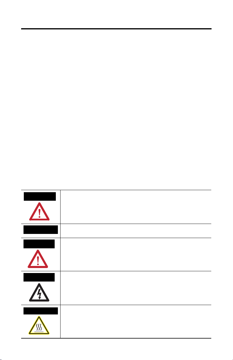
Throughout this manual, when necessary, we use notes to make you aware of safety considerations.
WARNING
IMPORTANT
ATTENTION
SHOCK HAZARD
BURN HAZARD
Identifies information about practices or circumstances that can cause an explosion in
a hazardous environment, which may lead to personal injury or death, property
damage, or economic loss.
Identifies information that is critical for successful application and understanding of
the product.
Identifies information about practices or circumstances that can lead to personal injury
or death, property damage, or economic loss. Attentions help you identify a hazard,
avoid a hazard and recognize the consequences.
Labels may be located on or inside the equipment (for example, drive or motor) to alert
people that dangerous voltage may be present.
Labels may be located on or inside the equipment (for example, drive or motor) to alert
people that surfaces may be dangerous temperatures.
Publication 2711P-IN028A-EN-P - December 2005
Page 3

PanelView Plus and VersaView CE Logic Module Pullup Board 3
About the Pullup Board
The PanelView Plus/VersaView CE Logic Module Pullup Board corrects intermittent
terminal resets (reboot or power cycle) that have typical reset cycle rates of
approximately 60 seconds. In addition, a 50 second lock-up is typically observed
during ‘Invoking Test Monitor’ terminal boot screen.
Affected product Series/Revisions and Date Codes are:
Product Catalog Numbers Series and Revisions Data Code
PanelView
Plus/VersaView CE
Ter mi na ls
PanelView
Plus/VersaView CE Logic
Modules
2711P-x7, 2711P-x10,
2711-x12, 2711P-x15,
6182H-x7, 6182H-x10,
6182H-x12, 6182H-x15
2711P-RP, 2711P-RP1,
2711P-RP2, 6189-RP,
6189-RPRH, 6189-RPEH
Series A, Revisions A to D 0203 thru 0705
Series A, Revision A through
Series C, Revision A
(Manufacturing dates
February 2003 to
July 2005)
0203 thru 0705
(Manufacturing dates
February 2003 to
July 2005)
Terminal Series and
Revision
Install the Pullup Board
WARNING
If you connect or disconnect any communication cable with
power applied to this module or any device on the network, an
electrical arc can occur. This could cause an explosion in
hazardous location installations. Be sure that power is removed or
the area is nonhazardous before proceeding.
Logic Module Series and
Revision
Date Codes
Publication 2711P-IN028A-EN-P - December 2005
Page 4

ATTENTION Work in a static free environment and wear a properly grounded
ESD wristband. Do not touch the Communication Module
connector or its internal circuitry to avoid ESD (Electrostatic
Discharge).
1. Disconnect power from the terminal.
2. If the Display Module is removed from the panel, set the terminal, display
side down, on a clean, flat, stable surface.
3. Remove the label covering the Communication Module connector on the
Logic Module.
Logic Module
Pullup Board
4. Position the Pullup Board over the Logic Module so that the connector on
bottom of the board aligns with connector on Logic Module.
5. Press the Pullup Board firmly into place.
Allen-Bradley, PanelView Plus, VersaView and Rockwell Automation are trademarks of Rockwell Automation, Inc.
Trademarks not belonging to Rockwell Automation are the property of their respective holders.
Publication 2711P-IN028A-EN-P - December 2005 PN 41061-372-01(1)
Supersedes Publication XXXX-X.X.X - Month Year Copyright © 2005 Rockwell Automation, Inc. A ll rights reserved. Printed in t he U.S.A.
 Loading...