

Page 1
Installation Instructions
IMPORTANT
LED Display Modules
Catalog Numbers 2711P-RDK15C, 2711P-RDT15C, 2711P-RDB15C, 2711P-RDT15AG,
2711P-RDK12C, 2711P-RDK12CK, 2711P-RDT12C, 2711P-RDT12CK, 2711P-RDT12AG,
2711P-RDB12C, 2711P-RDB12CK
Topi c Pag e
About the Product 1
Important User Information 2
Replace Display Module 3
Upgrade Firmware 3
Additional Resources 12
About the Product
Display modules with an LED (light-emitting diode) backlight are used by the
PanelView™ Plus 6 and PanelView Plus 700 to 1500 platforms. Earlier displays have a CCFL
(cold-cathode fluorescent lamp) backlight.
If you replace a 12-inch or 15-inch CCFL display with an LED display, you must upgrade the terminal firmware
for the device to operate correctly.
A firmware upgrade is not required for configured terminals that include a display module and logic module.
The upgrade is required only when ordering an LED display module to replace an existing CCFL display module.
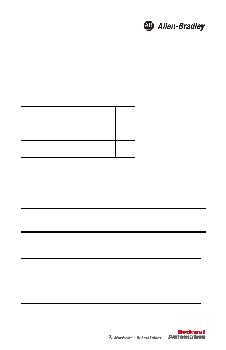
Each display module has a catalog number and a series letter. The series letter differentiates an
LED-backlit display from a CCFL-backlit display. You can find the series letter on the back of
the display. Refer to the table to identify the type of display you have.
Display Size Cat. Nos. LED Series Displays CCFL Series Displays
15-inch 2711P-RDK15C, 2711P-RDT15C,
12-inch 2711P-RDK12C, 2711P-RDK12CK,
2711P-RDB15C, 2711P-RDT15AG
2711P-RDT12C,2711P-RDT12CK
2711P-RDT12AG,
2711P-RDB12C,2711P-RDB12CK
Series C Series B or earlier
Series D Series C or earlier
Page 2
2 LED Display Modules
Important User Information
Solid-state equipment has operational characteristics differing from those of electromechanical equipment. Safety Guidelines for the
Application, Installation and Maintenance of Solid State Controls (publi cation SGI-1.1
sales office or online at http://www.rockwellautomation.com/literature/
equipment and hard-wired electromechanical devices. Because of this difference, and also because of the wide variety of uses for
solid-state equipment, all persons responsible for applying this equipment must satisfy themselves that each intended application of
this equipment is acceptable.
In no event will Rockwell Automation, Inc. be responsible or liable for indirect or consequential damages resulting from the use or
application of this equipment.
The examples and diagrams in this manual are included solely for illustrative purposes. Because of the many variables and
requirements associated with any particular installation, Rockwell Automation, Inc. cannot assume responsibility or liability for actual
use based on the examples and diagrams.
No patent liability is assumed by Rockwell Automation, Inc. with respect to use of information, circuits, equipment, or software
described in this manual.
Reproduction of the contents of this manual, in whole or in part, without written permission of Rockwell Automation, Inc., is
prohibited.
Throughout this manual, when necessary, we use notes to make you aware of safety considerations.
WARNIN G: Identifies information about practices or circumstances that can cause an explosion in a hazardous
environment, which may lead to personal injury or death, property damage, or economic loss.
available from your local Rockwell Automation®
) describes some important differences between solid-state
ATTENTION: Identifies information about practices or circumstances that can lead to personal injury or death,
property damage, or economic loss. Attentions help you identify a hazard, avoid a hazard and recognize the
consequences.
SHOCK HAZARD: Labels may be on or inside the equipment, for example, a drive or motor, to alert people that
dangerous voltage may be present.
BURN HAZARD: Labels may be on or inside the equipment, for example, a drive or motor, to alert people that
surfaces may reach dangerous temperatures.
IMPORTANT Identifies information that is critical for successful application and understanding of the product.
Rockwell Automation Publication 2711P-IN030A-EN-P - October 2013
Page 3
LED Display Modules 3
IMPORTANT
Replace Display Module
To replace a display module, refer to the appropriate manual under Additional Resources.
Before mounting the LED series display module, make sure the firmware installed in the logic module is at the
firmware revision listed in the table under Upgrade Firmware.
You must use CCFL series display module to upgrade the firmware; the display must be for 700 to 1500
platforms.
If no other display is available, the complete terminal must be returned to your local Allen-Bradley distributor
for exchange or repair.
Upgrade Firmware
Follow these steps to locate the firmware update for your terminal.
1. Go to http://www.rockwellautomation.com/support/pcdc.page
2. Click the Get Downloads tab.
3. Click Find Product Downloads.
4. From the All Families pull-down menu, choose PanelView Plus 6 700 - 1500 or
PanelView Plus 700 - 1500.
5. Click the family selection, then choose a firmware revision from the list.
The table shows the firmware revision required for your terminal.
For This PanelView Plus Family Choose This Firmware Revision
PanelView Plus/PanelView Plus CE 700 to 1500 5.10.11 or later
PanelView Plus 6 700 to 1500 7.00.20130619 or later
6. Click Find Downloads at the bottom of the Selections tab.
7. Under Downloads, click the show downloads icon to access the firmware.
8. Download the upgrade file (.exe) to a temporary folder on the same drive as FactoryTalk®
View Machine Edition (ME) software.
9. Run the upgrade file (.exe) installation procedure:
• The FUW is installed in the FactoryTalk View ME folder.
• The firmware upgrade package (.fup) file is installed into the folder specified during
the installation procedure.
You are now ready to run the FUW to upgrade the terminal firmware from a storage device or by
using a network connection.
.
Rockwell Automation Publication 2711P-IN030A-EN-P - October 2013
Page 4

4 LED Display Modules
IMPORTANT
Firmware Upgrade Wizard
The Firmware Upgrade Wizard (FUW) is used to upgrade the terminal firmware. Two methods
are provided for upgrading the firmware:
• Create a firmware upgrade card with the contents of the FUP file that you can then load
in the terminal to upgrade the firmware.
The firmware upgrade card can be a USB flash drive, CompactFlash (CF) card, or an SD
card, catalog number 1784-SDx.
• Upgrade firmware in a terminal connected to a computer over a direct network
connection. The network connection requires a computer with RSLinx® Enterprise
software installed.
RSLinx Enterprise software is required so you can choose the terminal to upgrade.
Use the latest version of RSLinx Enterprise software, which is available at
https://rockwellautomation.custhelp.com/app/answers/detail/a_id/49190.
You can run the FUW from within FactoryTalk View Studio software or from the Programs
menu on your computer:
• In FactoryTalk View Studio software, from the Tools menu, choose Firmware Upgrade
Wizard.
• Choose Start>Programs>Rockwell Software>FactoryTalk View>Tools>ME Firmware
Upgrade Wizard.
Upgrading Terminal Firmware from a Storage Device
Upgrading firmware from a storage device is a two-step process. First, you create a firmware
upgrade card with the required firmware files. Secondly, you load the card in the target terminal
to upgrade the firmware.
The firmware upgrade card can be a USB flash drive, CF card, or an SD card.
Create a Firmware Upgrade Card
Follow these steps to copy firmware files to a USB flash drive, CF card, or SD card.
1. Insert either a USB flash drive, CF card, or an SD card into the appropriate slot on your
computer.
2. Run the Firmware Upgrade Wizard:
a. In FactoryTalk View Studio software, from the Tools menu, choose Firmware
Upgrade Wizard.
b. Choose Start>Programs>Rockwell Software>FactoryTalk View>Tools>ME
Firmware Upgrade Wizard.
Rockwell Automation Publication 2711P-IN030A-EN-P - October 2013
Page 5

LED Display Modules 5
A
B
C
D
3. Follow these steps from the initial FUW dialog box.
a. Click Create firmware upgrade card (A).
b. Choose the location of the firmware card by browsing to the root directory of the
storage card loaded in your computer (for example, H:\ or B).
The firmware files are copied to this location. You can also specify a folder on the
hard drive.
c. From the Existing terminal type pull-down menu, choose a version v6.00-v7.00
PanelView Plus 6 terminal.
The example shows the firmware upgrade is for a 700 - 1500 PanelView Plus 6
terminal (C).
d. Click Next (D).
Rockwell Automation Publication 2711P-IN030A-EN-P - October 2013
Page 6

6 LED Display Modules
E
F
G
H
I
4. Follow these steps from this dialog box.
a. Browse to the location of the firmware source files on your computer, where the FUP
was installed (E).
b. From the Upgrade firmware version pull-down menu, choose the firmware revision
for the upgrade (F).
c. Click Next (G).
It can take several seconds for the next dialog box to appear while the FUP is being
retrieved.
5. Follow these steps from this dialog box.
a. Optionally choose the KEPServer drivers you want included in the firmware (H).
b. Click Next (I).
Kepware drivers are already installed on the PanelView Plus 6 terminals.
Rockwell Automation Publication 2711P-IN030A-EN-P - October 2013
Page 7

LED Display Modules 7
TIP
IMPORTANT
The final dialog box summarizes your choices for creating the firmware upgrade card.
6. Click Finish to update the firmware in the terminal.
A progress bar automatically updates as files are copied to the USB flash drive, CF card,
or SD card.
7. Click OK when the firmware upgrade completes successfully.
If the firmware files were copied to the hard drive, copy the files to the root directory of the USB flash
drive, CF card, or SD card.
8. Remove the USB flash drive, CF card, or SD card from your computer.
9. Proceed to the next section to use this firmware upgrade card to upgrade the terminal
firmware.
Upgrade Terminal Firmware by Using Firmware Upgrade Card
Follows these steps to transfer firmware files from the USB flash drive, CF card, or SD card to the
terminal. This is the firmware upgrade card created in the previous section.
• Do not remove or accidently disconnect the USB flash drive, CF card, or SD card while a
firmware upgrade is in process. This could corrupt the firmware and make the terminal
unstable.
• Do not power off the terminal during a firmware upgrade.
• USB hubs can produce unexpected behavior and are not recommended.
Rockwell Automation Publication 2711P-IN030A-EN-P - October 2013
Page 8

8 LED Display Modules
IMPORTANT
1. Insert the USB flash drive, CF card, or SD card into the appropriate slot on your
terminal.
The firmware upgrade automatically starts and displays this dialog box.
2. Press Upgrade or [F7] on the terminal to start the firmware upgrade.
The terminal restarts and displays a progress bar during the upgrade.
When the upgrade is complete, the terminal restarts, executing the new firmware.
3. Remove the USB flash drive, CF card, or SD card from the terminal.
Upgrade Terminal Firmware over the Network
You can upgrade firmware in a terminal connected to a computer over a direct network
connection. The network connection requires a computer running the FUW and RSLinx
Enterprise software.
RSLinx Enterprise software is required so you can choose the terminal on the network.
Use the latest version of RSLinx Enterprise software, which is available at
https://rockwellautomation.custhelp.com/app/answers/detail/a_id/49190
Follow these steps to copy firmware files to the terminal over a network by using RSLinx
Enterprise software and Ethernet communication.
1. Run the FUW:
a. In FactoryTalk View Studio software, from the Tools menu, choose Firmware
Upgrade Wizard.
b. Choose Start>Programs>Rockwell Software>FactoryTalk View>Tools>ME
Firmware Upgrade Wizard.
Rockwell Automation Publication 2711P-IN030A-EN-P - October 2013
.
Page 9

2. Click Upgrade firmware on terminal (A) and click Next (B).
A
B
C
D
3. Click Yes to continue.
It is not necessary to back up files on PanelView Plus 6 terminals.
4. Click Network Connection (using RSLinx Enterprise) (C).
This is the only valid selection for PanelView Plus 6 terminals.
LED Display Modules 9
5. Click Next (D).
Rockwell Automation Publication 2711P-IN030A-EN-P - October 2013
Page 10

10 LED Display Modules
IMPORTANT
E
F
G
6. Navigate to and select the terminal to receive the firmware update.
The highlighted selection in the figure below is only for illustration purposes. Your model c an be
different.
7. With the terminal selection highlighted, click Next.
8. Follow these steps from this dialog box.
a. Browse to the location of the firmware source files on your computer, where the FUP
was installed.
The default location is shown (E).
b. Choose the version of the upgrade firmware from the pull-down menu (F).
c. Click Next (G).
It can take several seconds for the next dialog box to appear while the FUP is being
retrieved.
Rockwell Automation Publication 2711P-IN030A-EN-P - October 2013
Page 11

LED Display Modules 11
9. From this dialog box, optionally choose the KEPServer drivers you want included in the
firmware, then click Next.
Kepware drivers are already installed on the PanelView Plus 6 terminals.
The final dialog box summarizes your choices for upgrading the terminal firmware.
10. Click Finish to update the firmware in the terminal.
11. Click Yes to continue with the update.
A progress bar updates as firmware files are copied to the terminal.
Rockwell Automation Publication 2711P-IN030A-EN-P - October 2013
Page 12

12. Click OK when the firmware upgrade is complete.
The terminal restarts, executing the new firmware.
Additional Resources
These documents contain additional information concerning related products from Rockwell
Automation.
Resource Description
PanelView Plus 6 HMI Terminals User Manual,
publication 2711P-UM006
PanelView Plus Terminals User Manual, publication
2711P-UM001
Industrial Automation Wiring and Grounding
Guidelines, publication1770-4.1
Product Certifications website,
http://www.rockwellautomation.com/
rockwellautomation/certification/overview.page
Provides information for installing, configuring, operating, and
troubleshooting PanelView Plus 6 terminals.
Provides information for installing, configuring, operating, and
troubleshooting the PanelView Plus terminals.
Provides general guidelines for installing a Rockwell Automation
industrial system.
Provides declarati ons of conformity, cer tificates, and other ce rtification
details.
You can view or download publications at http://www.rockwellautomation.com/literature/
. To
order paper copies of technical documentation, contact your local Allen-Bradley distributor or
Rockwell Automation sales representative.
Allen-Bradley, FactoryTalk, PanelView, Rockwell Software, Rockwell Automation, and RSLinx are trademarks of Rockwell Automation, Inc.
Trademarks not belonging to Rockwell Automation are property of their respective companies.
Rockwell Otomasyon Ticaret A.Ş., Kar Plaza İş Merkezi E Blok Kat:6 34752 İçerenköy, İstanbul, Tel: +90 (216) 5698400
Publication 2711P-IN030A-EN-P - October 2013 PN-213672
Supersedes Publication XXXX-X.X.X - Month Year Copyright © 2013 Rockwell Automation, Inc. All rights reserved. Printed in the U.S.A.
 Loading...