

Page 1
Installation Instructions
Display Module Bezel Replacement
Catalog Numbers 2711P-RBxxx
Language Page
English 3
Français 7
Deutsch 11
Español 15
Italiano 19
Português 23
Page 2
2 Display Module Bezel Replacement
Important User Information
Solid state equipment has operational characteristics differing from those of electromechanical equipment.
Safety Guidelines for the Application, Installation and Maintenance of Solid State Controls (publication
SGI-1.1 available from your local Rockwell Automation sales office or online at
http://rockwellautomation.com/literature) describes some important differences between solid state
equipment and hard-wired electromechanical devices. Because of this difference, and also because of the
wide variety of uses for solid state equipment, all persons responsible for applying this equipment must
satisfy themselves that each intended application of this equipment is acceptable.
In no event will Rockwell Automation, Inc. be responsible or liable for indirect or consequential damages
resulting from the use or application of this equipment.
The examples and diagrams in this manual are included solely for illustrative purposes. Because of the many
variables and requirements associated with any particular installation, Rockwell Automation, Inc. cannot
assume responsibility or liability for actual use based on the examples and diagrams.
No patent liability is assumed by Rockwell Automation, Inc. with respect to use of information, circuits,
equipment, or software described in this manual.
Reproduction of the contents of this manual, in whole or in part, without written permission of Rockwell
Automation, Inc., is prohibited.
Throughout this manual, when necessary, we use notes to make you aware of safety considerations.
WARNING
IMPORTANT
ATTENTION
SHOCK HAZARD
BURN HAZARD
Identifies information about practices or circumstances that can cause an explosion in
a hazardous environment, which may lead to personal injury or death, property
damage, or economic loss.
Identifies information that is critical for successful application and understanding of
the product.
Identifies information about practices or circumstances that can lead to personal injury
or death, property damage, or economic loss. Attentions help you to identify a hazard,
avoid a hazard, and recognize the consequences.
Labels may be on or inside the equipment, for example, a drive or motor, to alert
people that dangerous voltage may be present.
Labels may be on or inside the equipment, for example, a drive or motor, to alert
people that surfaces may reach dangerous temperatures.
Publication 2711P-IN018C-MU-P - March 2007
Page 3
Installation Instructions
Display Module Bezel Replacement
Catalog Numbers 2711P-RBxxx
English
Top ic Page
About This Publication 3
Required Tools 3
Precautions 4
Remove the Display Module Bezel 4
Replace the Display Module Bezel 6
About This Publication
This document shows how to remove and replace the display module bezel for
2711P PanelView Plus and PanelView Plus CE terminals.
Required Tools
These tools are required to install or replace terminal components:
• #00, #1, and #2 Phillips screwdriver
• Electrostatic discharge (ESD) wristband
Page 4
4 Display Module Bezel Replacement
Precautions
Before installing or replacing any components, disconnect power from the terminal.
During installation, take care not to touch any of the exposed electronic
components.
ATTENTION
ATTENTION
Disconnect all power from the terminal before installing or replacing any components.
Failure to disconnect power may result in electrical shock or damage to the terminal.
Work in a static free environment and wear a properly grounded electrostatic discharge
(ESD) wristband. Be careful when touching any of the exposed electronic components to
prevent damage from ESD.
Remove the Display Module Bezel
It is not necessary to remove the logic module or communication module before
removing the bezel, except for the PanelView Plus 700 or PanelView Plus CE 700.
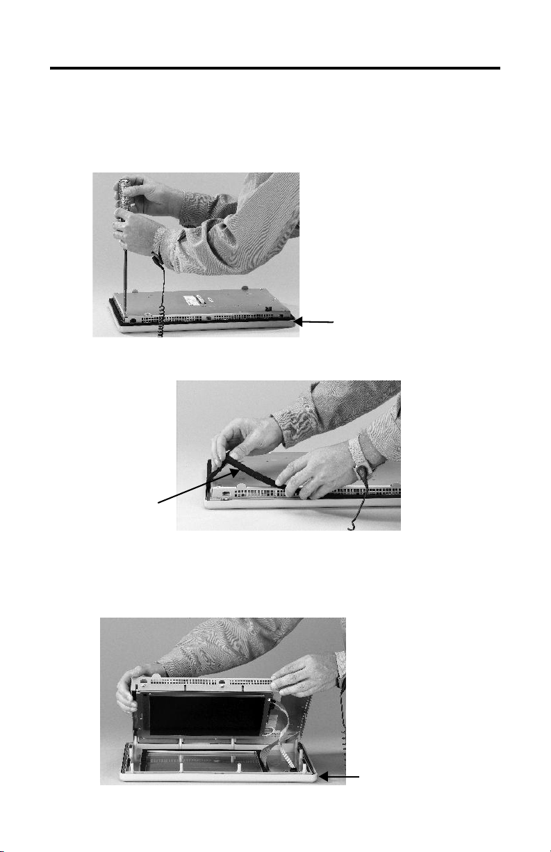
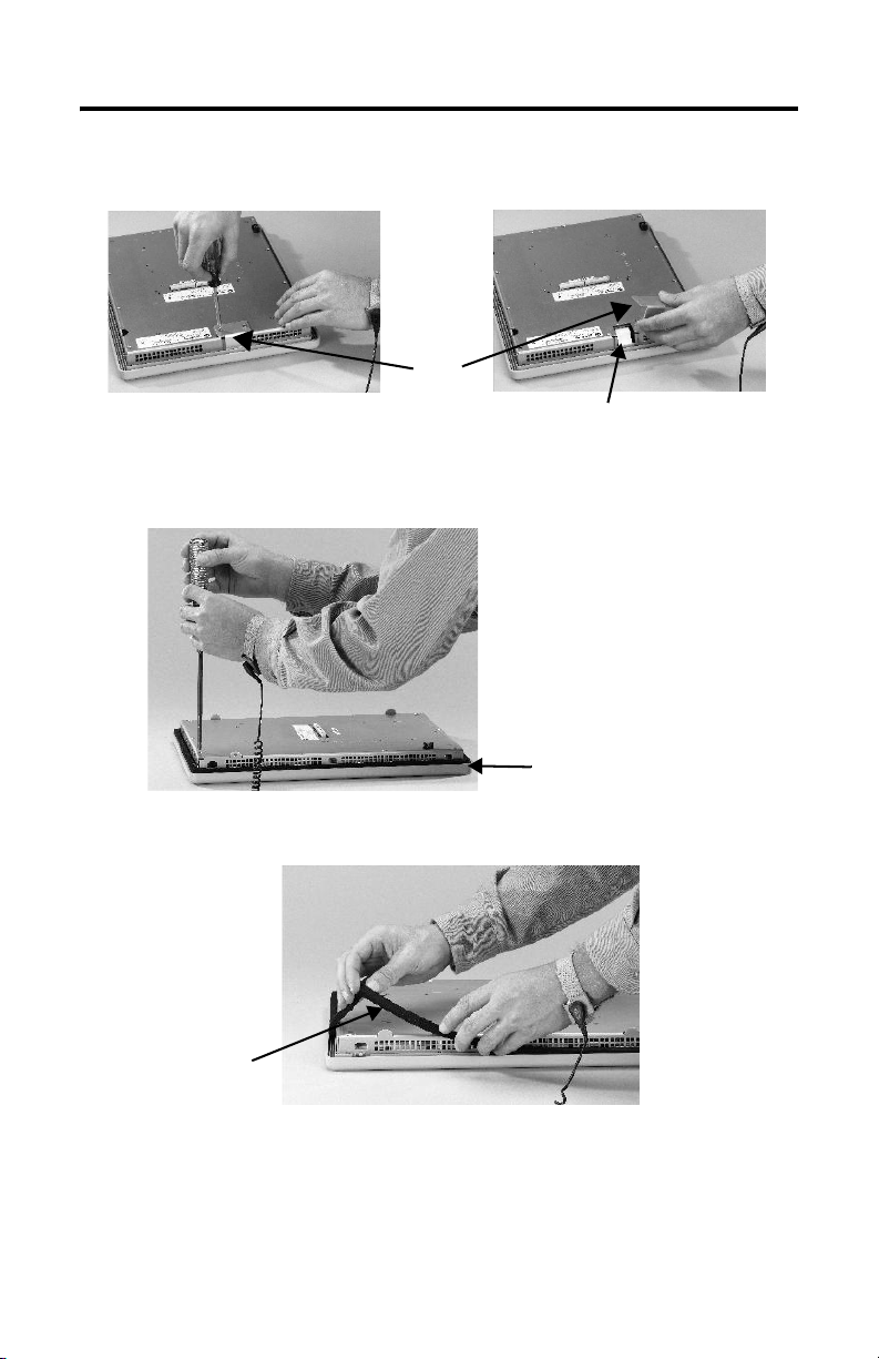
1. Disconnect power from the terminal.
2. Set the terminal, display side down, on a flat stable surface.
IMPORTANT
Wear a properly ground ESD wristband before touching any of the electronic
components in the logic module.
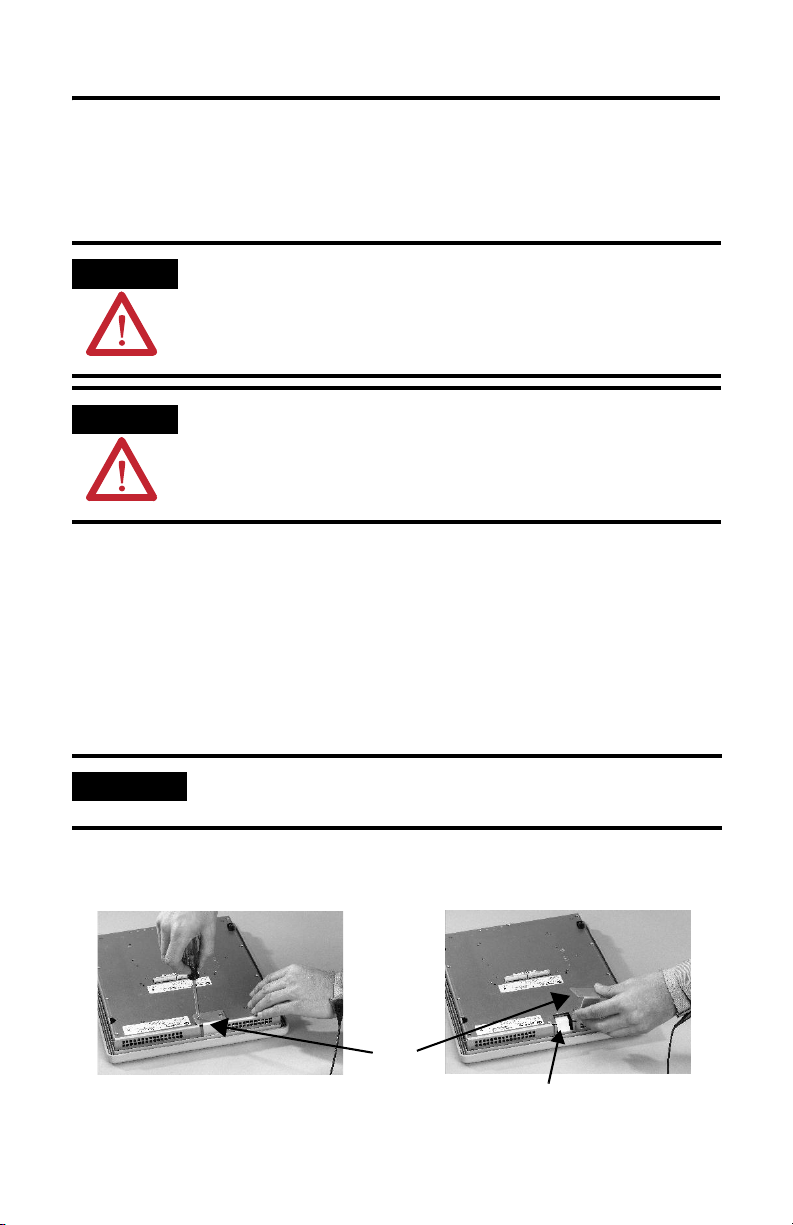
3. On touch screen terminals, remove the two screws that secure the small
metal plate to the back of the display module.
Plate
Touch Screen Connector
Publication 2711P-IN018C-MU-P - March 2007
Page 5
Display Module Bezel Replacement 5
4. Disconnect the touch screen connector.
5. Remove the screws from the back of the display module.
The number of screws varies for each terminal type.
Display Module Bezel
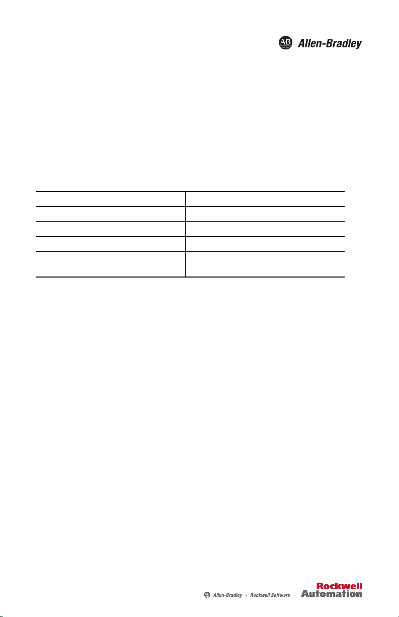
6. Remove the sealing gasket.
Sealing
Gasket
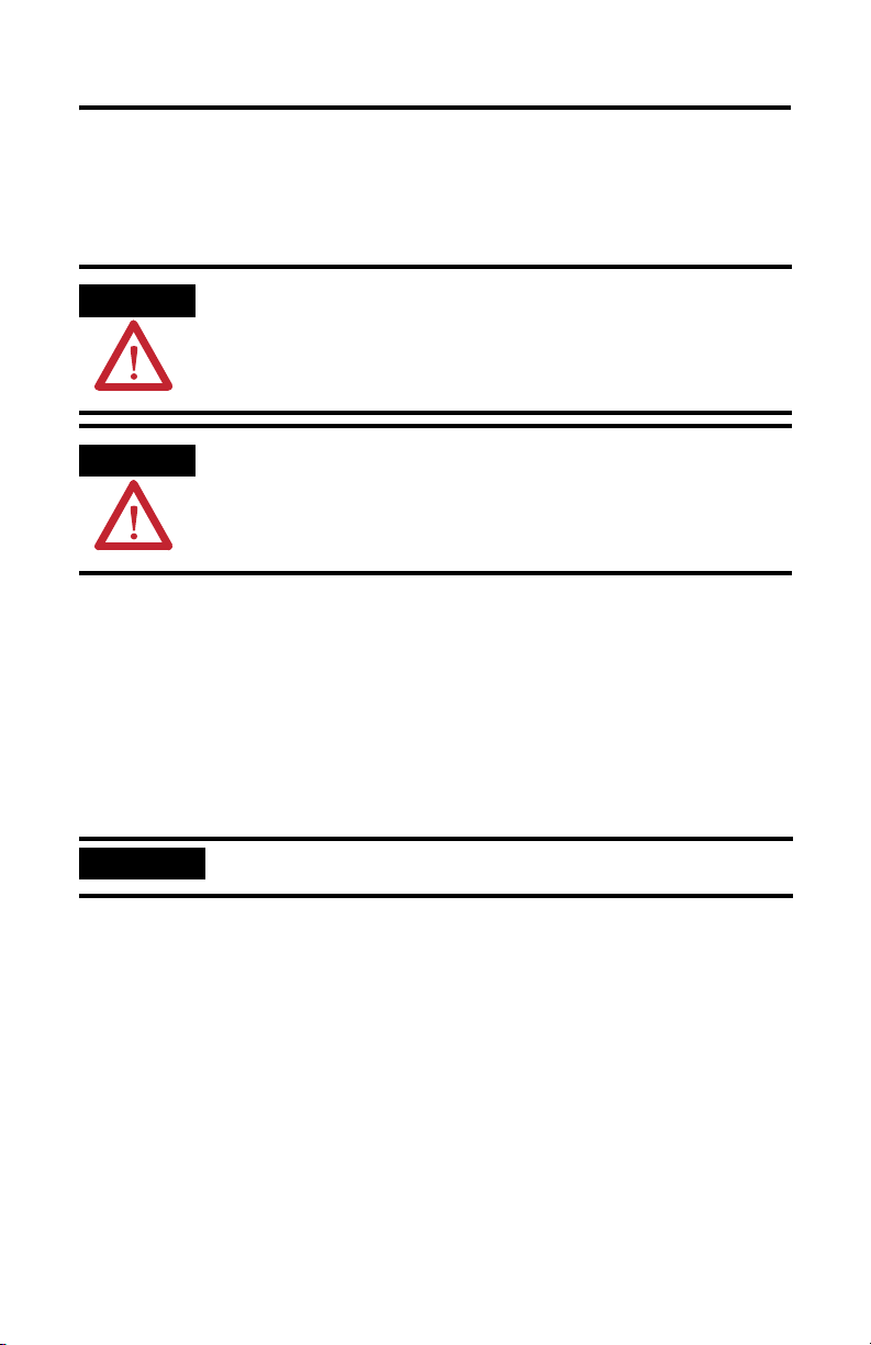
7. Lift the back of the display module away from the bezel.
Work on a clean, flat, stable surface to protect the display from debris,
scratches, and damage.
Display Module Bezel
Publication 2711P-IN018C-MU-P - March 2007
Page 6

6 Display Module Bezel Replacement
8. Detach all connectors, maximum of 3.
The number of connectors varies by model.
• IrDa connector, if present
• Function key connector
• Touch screen connector
9. Set the bezel aside.
Replace the Display Module Bezel
1. Make sure the new bezel is free of lint and marks before attaching.
2. Attach the connectors
The number of connectors varies by model.
• IrDa connector, if present
• Function key connector
• Touch screen connector
3. Place the back of the display module over the new bezel.
Be careful not to pinch any of the cables. Allow the touch screen connector
to extend out of the access opening.
4. Attach the touch screen connector.
5. Replace the sealing gasket.
6. Attach the screws that secure the display module to the bezel and tighten to
a torque of 1.35…1.58 Nm (12…14 lb-in).
7. On touch screen terminals, reattach the small metal plate to the back of the
display module using two screws and torque to 0.68Nm (6…8 lb-in).
Publication 2711P-IN018C-MU-P - March 2007
Page 7
Notice d’installation
Remplacement de la face avant
du module d'affichage
Référence 2711P-RBxxx
Français
Top ic Page
Outils nécessaires 7
Précautions 8
Retrait de la face avant du module d'affichage 8
Mise en place de la nouvelle face avant du
module d'affichage
Ce document indique comment retirer et remplacer la face avant du module
d'affichage des terminaux PanelView Plus 2711P et des pupitres opérateur ouverts
PanelView Plus CE 2711P.
Outils nécessaires
Pour remplacer les différents composants des terminaux PanelView Plus et
PanelView
Plus CE, vous aurez besoin des outils suivants :
• tournevis Phillips n° 1 et n° 2 ;
• bracelet antistatique.
10
Page 8
8 Remplacement de la face avant du module d'affichage
Précautions
Avant d'installer ou de remplacer des composants, déconnectez l'alimentation du
terminal. Pendant l'installation, veillez à ne pas toucher les composants
électroniques exposés.
ATTENTION
ATTENTION
Coupez toute alimentation du terminal avant d'installer ou de remplacer un
composant. En cas de non-respect de cette consigne, vous risquez de vous
électrocuter et
Travaillez dans un environnement exempt d'électricité statique et portez un bracelet
antistatique correctement relié à la terre. Veillez, lorsque vous touchez des composants
électroniques exposés, à ne pas les endommager par une décharge électrostatique.
/ ou d'endommager le terminal.
Retrait de la face avant du module d'affichage
Il n'est pas nécessaire de retirer le module logique ou le module de communication
pour démonter la face avant, sauf pour les PanelView Plus 700 et
PanelView Plus CE 700.
1. Déconnectez l'alimentation du terminal.
2. Posez le terminal, écran vers le bas, sur une surface plane et stable.
IMPORTANT
Mettez un bracelet antistatique correctement relié à la terre avant de toucher les
composants électroniques du module logique.
3. Sur les terminaux à dalle tactile, retirez les 2 vis qui maintiennent la petite
plaque métallique à l'arrière du module d'affichage.
Publication 2711P-IN018C-MU-P - March 2007
Page 9
Remplacement de la face avant du module d'affichage 9
4. Débranchez le connecteur (de la dalle tactile) en tirant sur la languette fixée
sur le connecteur.
Plaque
Connecteur de la dalle tactile
5. Retirez les vis située à l'arrière du module d'affichage.
Le nombre de vis varie d'un terminal à l'autre.
Face avant du module d'affichage
6. Retirez le joint d'étanchéité.
Joint
d'étanchéité
7. Soulevez l'arrière du module d'affichage pour le détacher de la face avant.
Publication 2711P-IN018C-MU-P - March 2007
Page 10

10 Remplacement de la face avant du module d'affichage
Travaillez sur une surface propre, plane et stable pour éviter de rayer ou
d'endommager l'écran.
Face avant du module d'affichage
8. Retirez tous les connecteurs (3 maximum).
Le nombre de connecteurs varie d'un modèle à l'autre :
• connecteur infrarouge (IrDa) ;
• connecteur des touches de fonction ;
• connecteur de la dalle tactile.
9. Mettez la face avant de côté.
Mise en place de la nouvelle face avant du module d'affichage
1. Avant de la mettre en place, vérifiez qu'il n'y a pas de poussière sur la
nouvelle face avant et qu'elle ne comporte pas de marques.
2. Branchez les connecteurs suivants.
Le nombre de connecteurs varie d'un modèle à l'autre.
• connecteur infrarouge (IrDa) ;
• connecteur des touches de fonction.
• connecteur de la dalle tactile.
3. Placez l'arrière du module d'affichage sur la nouvelle face avant.
Veillez à ne coincer aucun des câbles. Laissez le connecteur de la dalle
tactile dépasser de l'orifice d'accès.
4. Branchez le connecteur de la dalle tactile.
5. Remettez le joint d'étanchéité en place.
6. Remettez en place les vis qui maintiennent le module d'affichage à la face
avant et serrez-les avec un couple de 1,35 à 1,58
7. Sur les terminaux à dalle tactile, fixez la petite plaque métallique à l'arrière
du module d'affichage, à l'aide des 2
Publication 2711P-IN018C-MU-P - March 2007
vis.
Nm.
Page 11

Installationsanleitung
Austauschen der Frontblende des
Anzeigemoduls
Bestellnummer 2711P-RBxxx
Deutsch
Top ic Page
Erforderliche Werkzeuge 11
Vorsichtsmaßnahmen 12
Abnehmen der Frontblende des Anzeigemoduls 12
Anbringen der neuen Frontblende des
Anzeigemoduls
Dieses Dokument enthält Anleitungen zum Entfernen und Ersetzen der Frontblende
des Anzeigemoduls bei 2711P PanelView Plus- und PanelView Plus CE-Terminals.
Erforderliche Werkzeuge
14
Zum Installieren oder Austauschen der verschiedenen Komponenten der 2711P
PanelView Plus- und PanelView Plus CE-Terminals sind folgende Werkzeuge
erforderlich:
• Kreuzschlitz-Schraubendreher (#1 und #2)
• Erdungsband am Handgelenk
Page 12

12 Austauschen der Frontblende des Anzeigemoduls
Vorsichtsmaßnahmen
Unterbrechen Sie vor dem Installieren oder Austauschen von Komponenten stets
die Spannungsversorgung des Terminals. Achten Sie während der Installation
darauf, dass Sie keine freiliegenden elektronischen Komponenten berühren.
WARNUNG
WARNUNG
Unterbrechen Sie vor dem Installieren oder Austauschen von Komponenten stets die
Spannungsversorgung des Terminals. Wird die Spannungsversorgung nicht unterbrochen,
kann dies zu Stromschlägen und/oder zur Beschädigung des Terminals führen.
Arbeiten Sie in einer antistatischen Umgebung und tragen Sie ein Erdungsband
am Handgelenk. Zur Vermeidung von Schäden aufgrund elektrostatischer
Entladung gehen Sie beim Berühren der freiliegenden elektronischen
Komponenten äußerst vorsichtig vor.
Abnehmen der Frontblende des Anzeigemoduls
Das Entfernen des Logik- oder Kommunikationsmoduls vor dem Abnehmen der
Blende ist nur beim Terminal PanelView Plus 700 und PanelView Plus CE 700
erforderlich.
1. Unterbrechen Sie die Spannungsversorgung des Terminals.
2. Legen Sie das Terminal mit der Anzeige nach unten auf eine ebene, stabile
Oberfläche.
WICHTIG
Tragen Sie stets ein Erdungsband am Handgelenk, wenn Sie die elektronischen
Komponenten im Logikmodul berühren.
Publication 2711P-IN018C-MU-P - March 2007
Page 13

Austauschen der Frontblende des Anzeigemoduls 13
3. Bei Touchscreen-Terminals entfernen Sie die zwei Schrauben, mit denen die
kleine Metallplatte an der Rückseite des Anzeigemoduls befestigt ist.
Platte
Touchscreen-Steckverbinder
4. Entfernen Sie den (Touchscreen-) Steckverbinder durch Ziehen der Lasche
am Steckverbinder.
5. Entfernen Sie die Schrauben an der Rückseite des Anzeigemoduls.
Die Anzahl der Schrauben variiert je nach Terminaltyp.
Frontblende des Anzeigemoduls
6. Entfernen Sie die Dichtung.
Dichtung
7. Nehmen Sie die Rückseite des Anzeigemoduls von der Blende ab.
Publication 2711P-IN018C-MU-P - March 2007
Page 14

14 Austauschen der Frontblende des Anzeigemoduls
Arbeiten Sie auf einer sauberen, ebenen und stabilen Oberfläche, damit die
Anzeige nicht verschmutzt, verkratzt oder beschädigt wird.
Frontblende des Anzeigemoduls
8. Ziehen Sie alle Steckverbinder ab (maximal 3).
Die Anzahl der Steckverbinder variiert je nach Modell.
• IrDa-Steckverbinder
• Funktionstasten-Steckverbinder
• Touchscreen-Steckverbinder
9. Legen Sie die Blende beiseite.
Anbringen der neuen Frontblende des Anzeigemoduls
1. Vergewissern Sie sich vor dem Anbringen der Blende, dass diese fusselfrei ist
und keine Kratzer aufweist.
2. Bringen Sie die folgenden Steckverbinder wieder an.
Die Anzahl der Steckverbinder variiert je nach Modell.
• IrDa-Steckverbinder
• Funktionstasten-Steckverbinder
• Touchscreen-Steckverbinder
3. Setzen Sie die Rückseite des Anzeigemoduls auf die neue Blende.
Achten Sie darauf, dass Sie dabei die Kabel nicht abklemmen. Der
Touchscreen-Steckverbinder muss aus der Zugriffsöffnung herausragen.
4. Bringen Sie den Touchscreen-Steckverbinder an.
5. Bringen Sie die Dichtung wieder an (siehe Schritt 6 auf Seite 13).
6. Bringen Sie die Schrauben wieder an, mit denen das Anzeigemodul an der
Blende befestigt wird, und ziehen Sie diese mit einem Anzugsmoment von
1,35–1,58 Nm fest.
7. Bei Touchscreen-Terminals bringen Sie die kleine Metallplatte mit den zwei
Schrauben wieder an der Rückseite des Anzeigemoduls an.
Publication 2711P-IN018C-MU-P - March 2007
Page 15

Instrucciones de instalación
Reemplazo del bisel del módulo de
pantalla
Número de catálogo 2711P-RBxxx
Español
Top ic Page
Herramientas requeridas 15
Precauciones 16
Cómo desmontar el bisel del módulo de pantalla 16
Reemplazo del bisel del módulo de pantalla 18
Este documento muestra cómo extraer y reemplazar el bisel del módulo de pantalla
de los terminales 2711P PanelView Plus y PanelView CE.
Herramientas requeridas
Las herramientas requeridas para instalar o reemplazar los diversos componentes
de los terminales 2711P PanelView Plus y PanelView CE son:
• Destornillador Phillips #1 y #2
• Muñequera conductiva para evitar descargas electrostáticas (ESD)
Page 16

16 Reemplazo del bisel del módulo de pantalla
Precauciones
Antes de instalar o reemplazar cualquier componente, desconecte la alimentación
eléctrica del terminal. Durante la instalación, tenga cuidado de no tocar ninguno de
los componentes electrónicos expuestos.
ATENCIÓN
ATENCIÓN
Desconecte la alimentación eléctrica del terminal, antes de instalar o reemplazar
cualquier componente. El no desconectar la alimentación puede resultar en choque
eléctrico y/o daño al terminal.
Trabaje en un ambiente a prueba de descargas electrostáticas y use una muñequera
conductiva conectada a tierra para proteger el equipo contra ESD. Tenga cuidado de no
tocar ninguno de los componentes electrónicos expuestos para evitar el daño producido
por descarga electrostática (ESD).
Cómo desmontar el bisel del módulo de pantalla
No es necesario desmontar el módulo lógico ni el módulo de comunicación antes
de desmontar el bisel, excepto en el caso de PanelView Plus 700 y
PanelView CE 700 .
1. Desconecte la alimentación eléctrica del terminal.
2. Coloque el terminal, con el lado de la pantalla hacia abajo, sobre una
superficie plana y estable.
IMPORTANTE
3. En los terminales de pantalla táctil, quite los 2 tornillos que fijan la placa
pequeña de metal a la parte posterior del módulo de pantalla.
Use una muñequera conductiva para protección contra descargas electrostáticas (ESD)
antes de tocar cualquier componente electrónico del módulo lógico.
Publication 2711P-IN018C-MU-P - March 2007
Page 17

Reemplazo del bisel del módulo de pantalla 17
4. Desconecte el conector (de la pantalla táctil) tirando de la lengüeta pegada
al conector.
Placa
Conector de la pantalla táctil
5. Quite los tornillos de la parte trasera del módulo de pantalla. El número de
tornillos varía dependiendo del tipo de terminal.
Bisel del módulo de pantalla
6. Quite la empaquetadura de sellado.
Empaqueta
dura de
sellado
7. Levante la parte posterior del modulo de pantalla separándola del bisel.
Publication 2711P-IN018C-MU-P - March 2007
Page 18

18 Reemplazo del bisel del módulo de pantalla
Trabaje sobre una superficie limpia, plana y estable para proteger la pantalla
contra residuos, rasguños y daño.
Bisel del módulo de pantalla
8. Desacople todos los conectores (máximo 3).
El número de conectores varía según el modelo.
• Conector IrDa
• Conector de tecla de función
• Conector de la pantalla táctil
9. Coloque el bisel a un lado.
Reemplazo del bisel del módulo de pantalla
1. Asegúrese de que el nuevo bisel esté libre de pelusa y marcas antes de
instalarlo.
2. Acople los siguientes conectores.
El número de conectores varía según el modelo.
• Conector IrDa
• Conector de tecla de función
• Conector de la pantalla táctil
3. Coloque la parte posterior del modulo de pantalla sobre el nuevo bisel.
Tenga cuidado para no aplastar los cables.
Deje que el conector de la pantalla táctil se extienda hacia afuera de la
abertura de acceso.
4. Acople el conector de la pantalla táctil.
5. Vuelva a colocar la empaquetadura de sellado.17
6. Coloque los tornillos que fijan el módulo de pantalla al bisel y apriételos a
un par de 1.35…1.58 Nm (12…14 pulg.-lb).
7. En los terminales de pantalla táctil, vuelva a acoplar la placa pequeña de
metal a la parte posterior del módulo de pantalla con los 2 tornillos.
Publication 2711P-IN018C-MU-P - March 2007
Page 19

Istruzioni per l'installazione
Sostituzione della cornice del modulo di
visualizzazione
Codice di catalogo 2711P-RBxxx
Italiano
Top ic Page
Strumenti necessari 19
Precauzioni 20
Rimozione della cornice del modulo 20
Sostituzione della cornice del modulo 22
Questo documento illustra come rimuovere e sostituire la cornice del modulo di
visualizzazione dei terminali 2711P PanelView Plus e PanelView Plus CE.
Strumenti necessari
Gli strumenti necessari per installare o sostituire i vari componenti dei terminali
2711P PanelView Plus e PanelView Plus CE sono:
• Cacciavite a croce n° 1 e n° 2
• Bracciale elettrostatico (ESD)
Page 20

20 Sostituzione della cornice del modulo di visualizzazione
Precauzioni
Prima di installare o rimuovere qualsiasi componente, scollegare il terminale
dall’alimentazione. Durante l’installazione, non toccare i componenti elettronici.
ATTENZIONE
ATTENZIONE
Scollegare il terminale dal’alimentazione prima di installare i rimuovere qualsiasi
componente. Il mancato scollegamento dall’alimentazione può provocare danni al
terminale.
Lavorare in un ambiente privo di corrente statica e indossare una bracciale ESD
adeguatamente collegato a terra. Prestare particolare attenzione quando si toccano i
componenti elettronici per evitare danni dovuti a cariche elettrostatiche.
Rimozione della cornice del modulo
Per rimuovere la cornice, non occorre rimuovere il modulo di logica né il modulo
di comunicazione, tranne che con PanelView Plus 700 e PanelView Plus CE 700.
1. Scollegare il terminale dall’alimentazione.
2. Posare il terminale, con il lato display rivolto verso il basso, su una
superficie piana.
IMPORTANTE
Indossare un bracciale ESD adeguatamente collegato a terra prima di toccare i
componenti elettronici del modulo di logica.
3. Sui terminali touch screen, rimuovere le 2 viti che fissano la piccola lastra di
metallo al retro del modulo di visualizzazione.
4. Desconecte o conector (touch screen) puxando pela trava acoplada ao
conector.
Piastra
Connettore touch screen
Publication 2711P-IN018C-MU-P - March 2007
Page 21

Sostituzione della cornice del modulo di visualizzazione 21
5. Rimuovere le viti dal retro del modulo di visualizzazione. Il numero di viti
varia a seconda del tipo di terminale.
Cornice del modulo di visualizzazione
6. Rimuovere la guarnizione.
Guarnizione
7. Sollevare il retro del modulo di visualizzazione dalla cornice.
Lavorare su una superficie pulita, piatta e stabile per proteggere il display da
sporcizia, graffi e danni.
Cornice del modulo di
visualizzazione
Publication 2711P-IN018C-MU-P - March 2007
Page 22

22 Sostituzione della cornice del modulo di visualizzazione
8. Staccare tutti i connettori (massimo 3).
Il numero di connettori varia a seconda del modello.
• Connettore IrDa
• Connettore tasti funzione
• Connettore touch screen
9. Mettere da parte la cornice.
Sostituzione della cornice del modulo
1. Accertarsi che la nuova cornice sia priva di rigature e segni prima di
montarla.
2. Collegare i seguenti connettori.
Il numero di connettori varia a seconda del modello.
• Connettore IrDa
• Connettore tasto funzione
• Connettore touch screen
3. Posizionare il retro del modulo di visualizzazione sulla nuova cornice. Fare
attenzione a non pinzare i cavi.
Fare in modo che il connettore del touch screen si estenda al di fuori
dell’apertura di accesso.
4. Collegare il connettore touch screen
5. Sostituire la guarnizione.
6. Fissare la cornice al modulo di visualizzazione e serrare fino a raggiungere
una coppia di 1,35…1,58 Nm (12…14 in-lb).
7. Sui terminali a touch screen, ricollegare la piccola piastra di metallo al retro
del modulo di visualizzazione usando 2 viti.
Publication 2711P-IN018C-MU-P - March 2007
Page 23

Instruções de Instalação
Substituição da moldura do módulo de
display
Código de Catálogo 2711P-RBxxx
Português
Top ic Page
Ferramentas necessárias 23
Precauções 24
Remoção da moldura do módulo de display 24
Substituição da moldura do módulo de display 26
Este documento mostra como retirar e substituir a moldura do módulo de display
para terminais 2711P PanelView Plus e PanelView Plus CE.
Ferramentas necessárias
As ferram2711P entas necessárias para instalar ou substituir os vários componentes
dos terminais PanelView Plus e PanelView Plus CE são:
• Chave de fenda Phillips nº 1 e nº 2
• Pulseira de aterramento (ESD)
Page 24

24 Substituição da moldura do módulo de display
Precauções
Antes de instalar ou substituir qualquer componente, desligue a alimentação do
terminal. Durante a instalação, certifique-se de não tocar em nenhum componente
eletrônico exposto.
ATTENÇÃO
ATTENÇÃO
Antes de instalar ou substituir qualquer componente, desligue toda a alimentação do
terminal. A negligência em desligar a energia pode resultar em choque elétrico e/ou
danos ao terminal.
Trabalhe em um ambiente livre de estática e use uma pulseira ESD aterrada
adequadamente. Cuidado ao tocar em quaisquer componentes eletrônicos expostos para
evitar danos por descarga eletrostática (ESD).
Remoção da moldura do módulo de display
Não é necessário remover o Módulo de Lógica ou o Módulo de Comunicação antes
de retirar a moldura, exceto no PanelView Plus 700 e PanelView Plus CE 700.
1. Desligue a alimentação do terminal.
2. Coloque o terminal em uma superfície plana e estável com o lado do display
para baixo.
IMPORTANTE
3. Nos terminais com tela touch screen, remova os 2 parafusos que prendem a
pequena placa de metal à parte traseira do Módulo de Display.
Use uma pulseira ESD aterrada de forma adequada antes de tocar em qualquer
componente eletrônico do Módulo de Lógica.
4. Desconecte o conector (touch screen) puxando pela trava acoplada ao
conector.
Placa
Conector da tela touch screen
Publication 2711P-IN018C-MU-P - March 2007
Page 25

Substituição da moldura do módulo de display 25
5. Retire os parafusos traseiros do Módulo de Display. O número de parafusos
varia para cada tipo de terminal.
Moldura do Módulo de Display
6. Retirar a junta de vedação.
Junta de
Vedação
7. Levante a parte de trás do Módulo de Display, afastando-a da moldura.
Trabalhe em uma superfície limpa, plana e estável para proteger o display
de detritos, arranhões e danos.
Moldura do Módulo de Display
Publication 2711P-IN018C-MU-P - March 2007
Page 26

26 Substituição da moldura do módulo de display
8. Solte todos os conectores (máximo 3).
O número de conectores varia de acordo com o modelo.
• Conector IrDa
• Conector de tecla de função
• Conector de tela touch screen
9. Separe a moldura.
Substituição da moldura do módulo de display
1. Certifique-se que a nova moldura não tenha fiapos e marcas antes de
instalá-la.
2. Acople os seguintes conectores. O número de conectores varia de acordo
com o modelo.
• Conector IrDa
• Conector de tecla de função
• Conector de tela touch screen
3. Coloque a parte de trás do Módulo de Display sobre a nova moldura.
Cuidado para não prender nenhum dos cabos.
4. Deixe que o conector de tela touch screen se estenda para fora da abertura
de acesso.
5. Encaixe o conector de tela touch screen.
6. Recoloque a junta de vedação.
7. Coloque os parafusos que prendem o Módulo de Display à moldura e aperte
a um torque de 1,35…1,58 Nm (12…14 pol-lb).
8. Nos terminais de tela touch screen, recoloque a pequena placa de metal na
parte de trás do Módulo de Display usando 2 parafusos.
Publication 2711P-IN018C-MU-P - March 2007
Page 27

Page 28

Rockwell Automation Support
Rockwell Automation provides technical information on the Web to assist you in using its products. At
http://www.rockwellautomation.com/support/
technical and application notes, sample code and links to software service packs, and a MySupport feature that
you can customize to make the best use of these tools.
For an additional level of technical phone support for installation, configuration and troubleshooting, we offer
TechConnect support programs. For more information, contact your local distributor or Rockwell Automation
representative, or visit http://www.rockwellautomation.com/support/
Installation Assistance
If you experience a problem within the first 24 hours of installation, please review the information that's
contained in this manual. You can also contact a special Customer Support number for initial help in getting your
product up and running.
United States or Canada 1.440.646.3434
Outside United States
or Canada
Use the Worldwide Locator
http://www.rockwellautomation.com/support/americas/phone_en.html
your local Rockwell Automation representative.
New Product Satisfaction Return
Rockwell Automation tests all of its products to ensure that they are fully operational when shipped from the
manufacturing facility. However, if your product is not functioning and needs to be returned, follow these
procedures.
United States Contact your distributor. You must provide a Customer Support case number (call the
phone number above to obtain one) to your distributor to complete the return process.
Outside United States Please contact your local Rockwell Automation representative for the return
procedure.
, you can find technical manuals, a knowledge base of FAQs,
.
at
, or contact
Documentation Feedback
Your comments will help us serve your documentation needs better. If you have any suggestions on how to
improve this document, complete this form, publication RA-DU002
http://literature.rockwellautomation.com
Allen-Bradley, Rockwell Software, Rockwell Automation, and TechConnect are trademarks of Rockwell Automation, Inc.
Trademarks not belonging to Rockwell Automation are property of their respective companies.
.
Publication 2711P-IN018C-MU-P - March 2007 PN 41061-325-01(3)
Supersedes Publication 2711P-IN018B-MU-P - January 2005 Copyright © 2007 Rockwell Automation, Inc. All rights reserved. Printed in the U.S.A.
, available at
 Loading...