

Page 1

Installation Instructions
Adapter Kit for PanelView 1200/1200e Touch Screen Terminal Cutout
Catalog Numbers 2711-NR5T, 2711P-RAT12E2
Topic Page
About This Publication 1
Important User Information 2
About the Cutout Adapter Plate 3
Parts List 3
Required Tools 4
Disconnect Power to the Terminal 4
Remove the Existing Terminal from the Panel 4
Attach the Cutout Adapter Plate to the Panel 5
Mount the New Terminal in the Cutout Adapter Plate 6
Additional Resources 7
About This Publication
This publication shows how to use the cutout adapter kit to mount the following
terminals into an existing PanelView 1200/1200e touch screen terminal cutout.
• PanelView 1000/1000e touch screen
• PanelView Plus 1250 touch screen
• PanelView Plus CE 1250 touch screen
• RAC6182 12.1 in. touch screen
Publication 2711P-IN014D-EN-P - July 2007
Page 2
2 Adapter Kit for PanelView 1200/1200e Touch Screen Terminal Cutout
Important User Information
Solid state equipment has operational characteristics differing from those of electromechanical equipment.
Safety Guidelines for the Application, Installation and Maintenance of Solid State Controls (publication
SGI-1.1 available from your local Rockwell Automation sales office or online at
http://literature.rockwellautomation.com
equipment and hard-wired electromechanical devices. Because of this difference, and also because of the
wide variety of uses for solid state equipment, all persons responsible for applying this equipment must
satisfy themselves that each intended application of this equipment is acceptable.
In no event will Rockwell Automation, Inc. be responsible or liable for indirect or consequential damages
resulting from the use or application of this equipment.
The examples and diagrams in this manual are included solely for illustrative purposes. Because of the many
variables and requirements associated with any particular installation, Rockwell Automation, Inc. cannot
assume responsibility or liability for actual use based on the examples and diagrams.
No patent liability is assumed by Rockwell Automation, Inc. with respect to use of information, circuits,
equipment, or software described in this manual.
Reproduction of the contents of this manual, in whole or in part, without written permission of Rockwell
Automation, Inc., is prohibited.
Throughout this manual, when necessary, we use notes to make you aware of safety considerations.
) describes some important differences between solid state
WARNING
IMPORTANT
ATTENTION
SHOCK HAZARD
BURN HAZARD
Identifies information about practices or circumstances that can cause an explosion in
a hazardous environment, which may lead to personal injury or death, property
damage, or economic loss.
Identifies information that is critical for successful application and understanding of
the product.
Identifies information about practices or circumstances that can lead to personal injury
or death, property damage, or economic loss. Attentions help you to identify a hazard,
avoid a hazard, and recognize the consequences.
Labels may be on or inside the equipment, for example, a drive or motor, to alert
people that dangerous voltage may be present.
Labels may be on or inside the equipment, for example, a drive or motor, to alert
people that surfaces may reach dangerous temperatures.
Publication 2711P-IN014D-EN-P - July 2007
Page 3
Adapter Kit for PanelView 1200/1200e Touch Screen Terminal Cutout 3
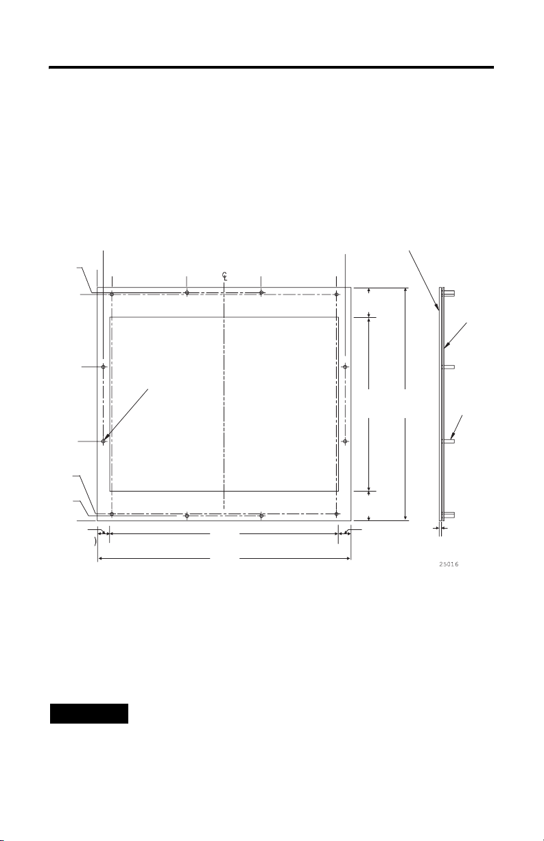
About the Cutout Adapter Plate
The cutout adapter plate is designed to fit into the existing cutout and stud-mounts
for the PanelView 1200/1200e terminals with minor modifications. See the cutout
assembly directions.
Dimensions are given in inches (mm).
Front and Side Views
13.20
(335)
13.09
(332.5)
8.90
(226)
4.60
(117)
0.40 (10)
0.35 (3)
0.84
0
(21)
#10-32
Mounting
Studs
TYP 12 PLS.
5.19
(132)
9.49
(241)
13.84
(352)
14.34
(364)
10.07
(255)
Front Bezel
13.49
(343)
Gasket
#10-32
Mounting
Studs
0.29 (7)
0
0.72
(18)
(337)
14.69
(373)
1.71
(44)
0.72
(18)
Parts List
The cutout adapter kit includes:
• one touch screen cutout adapter plate with gasket and ball bearing spacers.
• 12, #10-32 nuts with flat washers.
TIP
The adapter plate cutout template for the new terminal is shipped with the
new terminal and is not included in this kit.
Publication 2711P-IN014D-EN-P - July 2007
0.13 (3)13.25
Page 4

4 Adapter Kit for PanelView 1200/1200e Touch Screen Terminal Cutout
Required Tools
These items are required to install the cutout adapter plate.
• Center punch
• Scriber
• Hammer
• Power jig saw
• Power drill with 7/32 inch (6 mm) drill bit
• Socket driver with 3/8 inch socket
• Torque wrench capable of 1.1 Nm (10 lb-in)
• Metal file
To install the terminal, you need a slot or Phillips screwdriver.
Disconnect Power to the Terminal
Follow these steps to make sure that the power has been removed to the terminal.
1. Disconnect power at the source and remove the power cord from the
PanelView 1200/1200e terminal.
2. Disconnect all communication cables from the terminal.
ATTENTION
Make sure that the power cord of the terminal is disconnected, and that all
cables have been disconnected from the rear of the terminal.
Remove the Existing Terminal from the Panel
Follow these steps to remove the terminal from the panel.
1. Remove the mounting clips or nuts and washers that secure the PanelView
1200/1200e terminal to the panel.
2. Slide the terminal out from the panel.
Publication 2711P-IN014D-EN-P - July 2007
Page 5

Adapter Kit for PanelView 1200/1200e Touch Screen Terminal Cutout 5
Attach the Cutout Adapter Plate to the Panel
Follow these steps to attach the cutout adapter plate to the panel.
1. Align the cutout adapter template to the desired position.
IMPORTANT
The cutout adapter plate for the new terminal does not fit exactly over the
existing PanelView 1200/1200e terminal cutout and stud-mounts. The new
terminal is wider than the 1200/1200e terminal and requires a greater width in
the panel, so modifications are required. Determine how the new terminal is to
be placed: side left, side right, or centered.
Dimensions are given in inches (mm).
0.35 (3)
13.20
0
0.40
(10)
0.84 (21)
0
(335)
13.09
(332.5)
New Cutout Adapter
Bezel Line
8.90
(226)
New 1000/1000e
Cutout Required
4.60
(117)
0.29 (7)
5.19
(132)
Existing
1200/1200e
Cutout
14.69
(373)
9.49
(241)
13.84
(352)
14.34
(364)
Adapter
Plate Stud
13.49
(343)
New
Cutout Required
2. Using the cutout adapter template, mark the cutout areas that require
cutting, and where required, mark additional stud holes.
3. Cut the excess material from the sides of the existing PanelView 1200/1200e
terminal cutout and file clean the new cutout edges.
4. If required, drill the additional 7/32 inch holes for the cutout adapter studs.
5. Push the cutout adapter plate onto the panel until the gasket material is flush
with the front of the panel.
Publication 2711P-IN014D-EN-P - July 2007
Page 6

6 Adapter Kit for PanelView 1200/1200e Touch Screen Terminal Cutout
6. Using the 12 nuts with flat and lock washers, fasten the cutout adapter plate
to the panel.
Tighten the washers until the gasket is slightly compressed against the front
of the panel.
7. Using the torque wrench, tighten the nuts to not more than 1.1 Nm (10 lb-in)
to maintain the NEMA Type 4X rating.
Do not overtighten.
Mount the New Terminal in the Cutout Adapter Plate
Follow these steps to mount the new terminal into the cutout adapter plate.
1. Insert the new terminal into the adapter plate cutout until the terminal
gasket is flush with the front of the adapter plate.
2. Install the six mounting clips according to the installation instructions
provided with the new terminal.
The ends of the clips slide into the slots on the terminal.
Screw Driver Slot
Mounting
Mounting Slot
Adapter Plate
Clip
Mounting
Stud
Mounting
Clip
3. Tighten the screws on the mounting clips by hand until the gasket seal
contacts the mounting surface uniformly.
4. Using the torque wrench, tighten the screws on the mounting clips to the
specified torque rating provided in the installation instructions of the new
terminal.
Do not overtighten.
Publication 2711P-IN014D-EN-P - July 2007
Screwdriver
Slot
Page 7

Adapter Kit for PanelView 1200/1200e Touch Screen Terminal Cutout 7
ATTENTION
The new terminal is now ready for operation.
Tighten the mounting clips to the specified torque to provide a proper seal and
to prevent potential damage to the product. Allen-Bradley assumes no
responsibility for water or chemical damage to the product or other equipment
within the enclosure because of improper installation.
Additional Resources
You can view or download publications at
http://literature.rockwellautomation.com
documentation, contact your local Rockwell Automation distributor or sales
representative.
. To order paper copies of technical
Publication 2711P-IN014D-EN-P - July 2007
Page 8

Rockwell Automation Support
Rockwell Automation provides technical information on the Web to assist you in
using its products. At http://support.rockwellautomation.com
technical manuals, a knowledge base of FAQs, technical and application notes,
sample code and links to software service packs, and a MySupport feature that you
can customize to make the best use of these tools.
For an additional level of technical phone support for installation, configuration,
and troubleshooting, we offer TechConnect Support programs. For more
information, contact your local distributor or Rockwell Automation representative,
or visit http://support.rockwellautomation.com
.
Installation Assistance
If you experience a problem with a hardware module within the first 24 hours of
installation, please review the information that's contained in this manual. You can
also contact a special Customer Support number for initial help in getting your
module up and running.
, you can find
United States 1.440.646.3434
Outside United
States
Monday – Friday, 8am – 5pm EST
Please contact your local Rockwell Automation representative for any
technical support issues.
New Product Satisfaction Return
Rockwell tests all of its products to ensure that they are fully operational when
shipped from the manufacturing facility. However, if your product is not
functioning, it may need to be returned.
United States Contact your distributor. You must provide a Customer Support case number
Outside United
States
Allen-Bradley, PanelView, TechConnect, and Rockwell Automation are trademarks of Rockwell Automation, Inc.
Trademarks not belonging to Rockwell Automation are property of their respective companies.
Publication 2711P-IN014D-EN-P - July 2007 PN 14548
Supersedes Pub lication 2711P-IN014C-E N-P - March 2007 Copyright © 20 07 Rockwell Automatio n, Inc. All rights reser ved. Printed in the U.S.A.
(see phone number above to obtain one) to your distributor in order to
complete the return process.
Please contact your local Rockwell Automation representative for return
procedure.
 Loading...