

Page 1

Installation Instructions
Adapter Kit for PanelView 1400e Touch Screen Terminal Cutout
2711-NR7T, 2711P-RAT12E
Description
Package Contents
Use the Cutout Adapter Kit to mount the following terminals into an
existing PanelView 1400e Touch Screen terminal cutout.
• PanelView 1000 Touch
• PanelView 1000e Touch
• RAC6182 12.1 inch Industrial Computer Touch
• PanelView Plus 1250 Touch
The Cutout Adapter Kit includes:
• 1 touch screen cutout adapter plate with gasket
• 12 #10-32 nuts with flat washers
To install the terminal, you need:
• slot or Phillips screwdriver
Page 2
2 Adapter Kit for PanelView 1400e Touch Screen Terminal Cutout
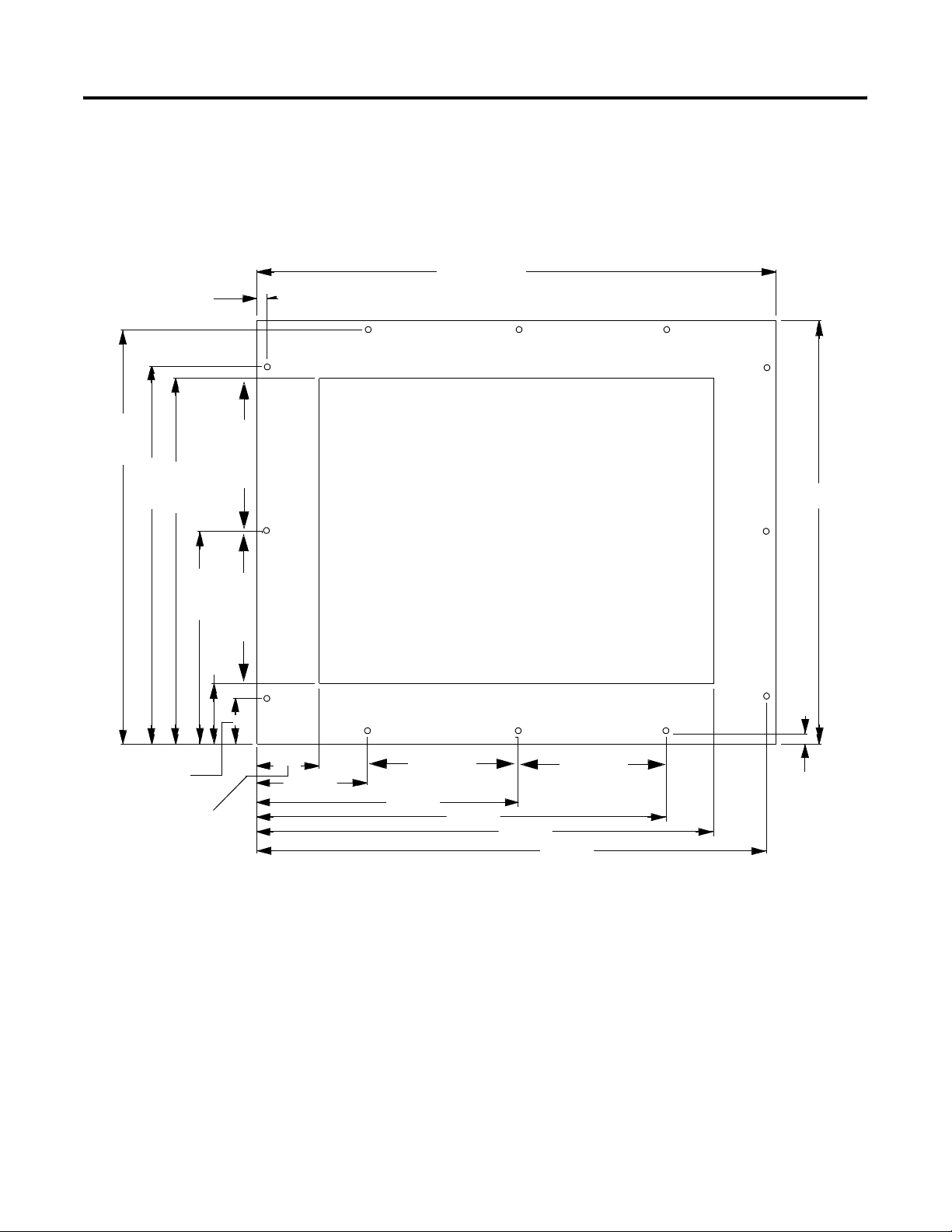
Dimensions
.340 (8.6 mm)
13.630
)
(346.2 mm)
)
m
m
5
0
m
8
m
2
4
1
.
0
.
3
.
2
.
7
2
1
5
1
1
0
3
(
3
(
5.0 (127 mm)
The cutout adapter plate is designed to fit into the existing cutout and
stud-mounts for the PanelView 1400e. The following illustration
shows the cutout assembly dimensions. The dimensions are given in
inches (mm).
17.380 (441.4 mm)
7
.
1
0
9
3
)
m
m
.
5
8
3
4
(
6.985
(177.4 mm)
5.0 (127 mm)
1.951
(49.5 mm)
8
.
5
4
1
)
m
3
(
7
.
7
m
2
.
0
6
7
)
m
2
5
m
.
5
(
3
.
6
9
0
m
)
.
7
m
9
(
3
5.0 (127 mm )
9
.
6
8
.
0
7
2
(
2
0
m
m
)
9
.
0
1
6
3
)
m
m
3
4
7
(
.
7
1
8
3
(
8
5
.
3
.
9
3
1
m
m
(
5.0 (127 mm)
)
7
.
0
4
1
0
m
4
3
.
8
2
.
0
3
4
)
m
8
(
.
6
m
)
m
Publication 2711-IN023B-EN-P - November 2002
Page 3

Adapter Kit for PanelView 1400e Touch Screen Terminal Cutout 3
Mounting the Cutout Adapter and New Terminal
Follow the steps below to mount the new terminal into the existing
PanelView 1400e Touch Screen terminal cutout.
Disconnect the Terminal
1. Disconnect power at the source and remove the power cord
from the PanelView 1400e terminal.
2. Disconnect all communication cables from the PanelView 1400e
terminal.
ATTENTION
Make sure that the power cord of the PanelView 1400e terminal is
disconnected, and that all cables have been disconnected from the
rear of the terminal.
Remove the Existing Terminal
1. Remove the mounting clips or nuts and washers that secure the
PanelView 1400e terminal to the panel.
2. Slide the existing terminal out from the terminal.
Attach the Cutout Adapter Plate to the Panel
1. Align the cutout adapter to the desired position.
2. Push the cutout adapter plate onto the panel until the gasket
material is flush with the front of the panel.
3. Using the 12 nuts with flat washers, fasten the cutout adapter
plate to the panel.
Tighten the washers until the gasket is slightly compressed.
4. Using the torque wrench, tighten the nuts to no more than 10
inch-pounds (a torque of 10 inch-pounds attains a NEMA Type
4X rating). Do not over-tighten.
Publication 2711-IN023B-EN-P - November 2002
Page 4

Screw Driver Slot
Mounting Slot
Adapter Plate
Attach the Terminal to Adapter Plate
1. Insert the new touch screen terminal into the adapter plate
cutout until the terminal gasket is flush with the front of the
adapter plate.
2. Install the mounting clips according to the Installation
Instructions of the new terminal. The ends of the clips slide into
the slots on the terminal.
Mounting
Mounting Slot
Screw Driver Slot
Mounting Clip
3. Tighten the screws on the mounting clips by hand until the
gasket seal contacts the mounting surface uniformly.
4. Using the torque wrench, tighten the screws on the mounting
clips to the torque rating provided in the Installation Instructions
of the new terminal. Do not overtighten.
ATTENTION
Tighten mounting clips to the proper torque to provide a proper seal
and to prevent potential damage to the terminal. Allen-Bradley
assumes no responsibility for water or chemical damage to the
terminal or other equipment within the enclosure because of improper
installation.
The new touch screen terminal is now ready for operation.
PanelView, PanelView Plus, Allen-Bradley, and Rockwell Automation are trademarks of
Rockwell Automation, Inc.
Trademarks not belonging to Rockwell Automation are property of their respective companies.
Publication 2711-IN023B-EN-P - November 2002 4 PN 41061-167-01(2)
Copyright © 2002 Rockwell Automation, Inc . All rights reserved. Printed in the U.S.A.
 Loading...