

Page 1

Installation Instructions
Cutout Adapter Kit
for PanelView Plus 400 Keypad and 600 Touch Terminals
2711P-RAK4
Inside...
English....................................................... 3
Français..................................................... 9
Deutsch ................................................... 15
Italiano.................................................... 21
Español.................................................... 27
Português................................................ 33
Publication 2711P-IN020A-MU-P
Page 2
2 Cutout Adapter Kit
Important User Information
Solid state equipment has operational characteristics differing from those of electromechanical equipment.
Safety Guidelines for the Application, Installation and Maintenance of Solid State Controls (Publication
SGI-1.1 available from your local Rockwell Automation sales office or online at
http://www.ab.com/manuals/gi) describes some important differences between solid state equipment and
hard-wired electromechanical devices. Because of this difference, and also because of the wide variety of
uses for solid state equipment, all persons responsible for applying this equipment must satisfy themselves
that each intended application of this equipment is acceptable.
In no event will Rockwell Automation, Inc. be responsible or liable for indirect or consequential damages
resulting from the use or application of this equipment.
The examples and diagrams in this manual are included solely for illustrative purposes. Because of the many
variables and requirements associated with any particular installation, Rockwell Automation, Inc. cannot
assume responsibility or liability for actual use based on the examples and diagrams.
No patent liability is assumed by Rockwell Automation, Inc. with respect to use of information, circuits,
equipment, or software described in this manual.
Reproduction of the contents of this manual, in whole or in part, without written permission of Rockwell
Automation, Inc. is prohibited.
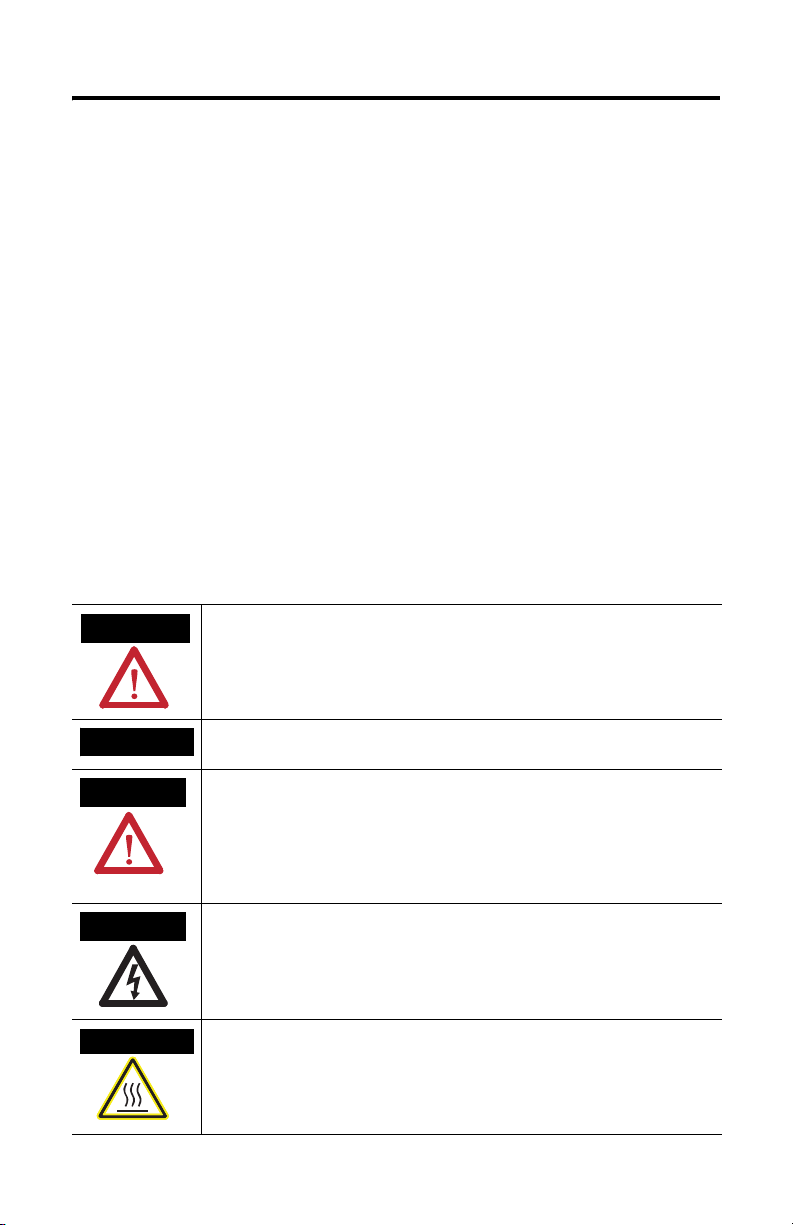
Throughout this manual we use notes to make you aware of safety considerations.
WARNING
Identifies information about practices or circumstances that can cause an explosion in a
hazardous environment, which may lead to personal injury or death, property damage,
or economic loss.
IMPORTANT
ATTENTION
SHOCK HAZARD
BURN HAZARD
Identifies information that is critical for successful application and understanding of the
product.
Identifies information about practices or circumstances that can lead to personal injury
or death, property damage, or economic loss. Attentions help you:
• identify a hazard
• avoid a hazard
• recognize the consequence
Labels may be located on or inside the drive to alert people that dangerous voltage may
be present.
Labels may be located on or inside the drive to alert people that surfaces may be
dangerous temperatures.
Publication 2711P-IN020A-MU-P
Page 3

Installation Instructions
Cutout Adapter Kit
for PanelView Plus 400 Keypad and 600 Touch Terminals
Catalog Number 2711P-RAK4
English
Description
This document provides instructions on how to mount a PanelView Plus 400 Keypad or 600
Touch terminal using an adapter plate into an existing PanelView Standard 550 Keypad
cutout.
Package Contents
The Cutout Adapter Kit includes:
• cutout adapter plate with gasket
• 6 #8-32 nuts with lock washers
Tools Required
The following tools are required for installation:
• socket driver with 11/32 inch socket
• torque wrench capable of 12 in-lb (1.36 N•m)
Publication 2711P-IN020A-MU-P
Page 4

4 Cutout Adapter Kit
Disconnect the Terminal
1. Disconnect power at the source and remove the power cord from the
PanelView terminal.
2. Disconnect all communication cables from the terminal.
ATTENTION
Make sure the power cord of the PanelView terminal is
disconnected and that all cables have been
disconnected from the terminal.
!
Remove the Existing Terminal
1. Remove the self-locking nuts that secure the terminal to the panel.
2. Slide the existing terminal out from panel.
Publication 2711P-IN020A-MU-P
Page 5
Cutout Adapter Kit 5
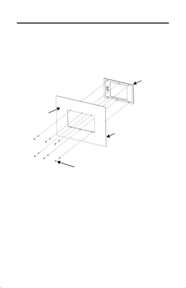
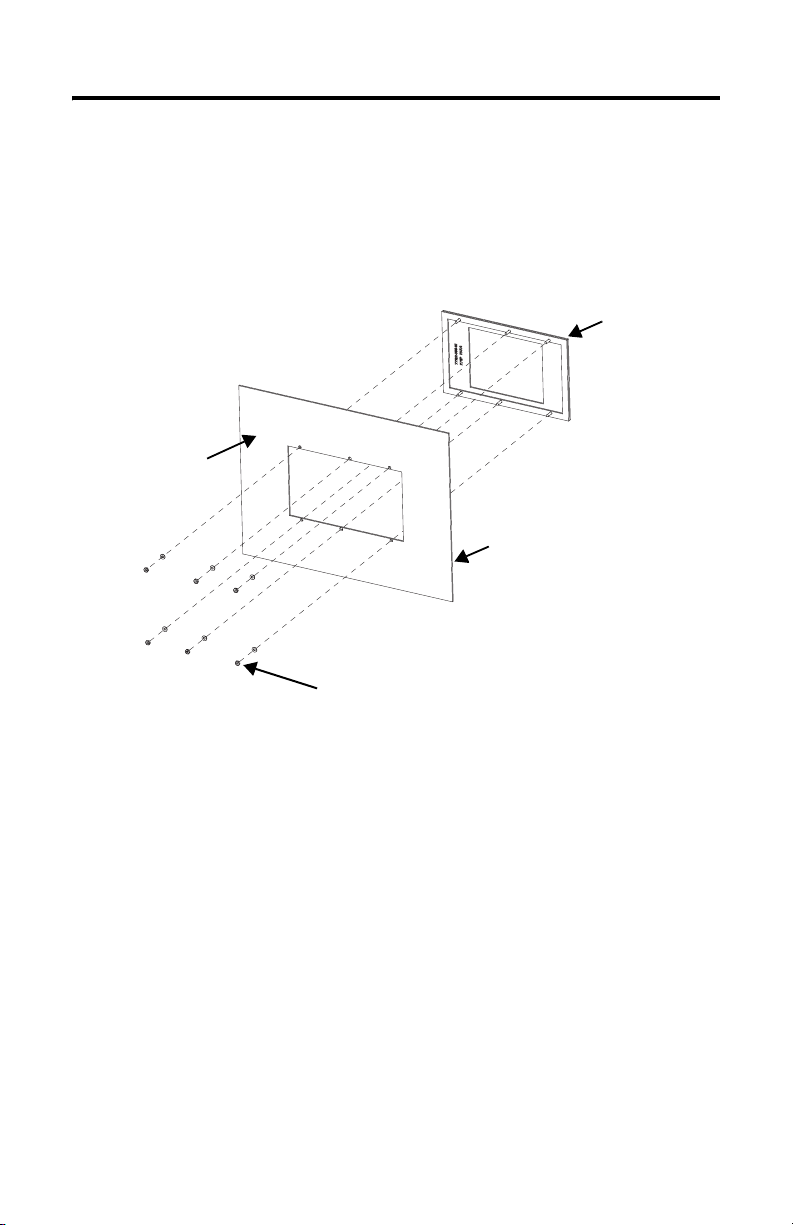
Attach the Adapter Plate to the Panel
1. Align the studs on the cutout adapter plate with the existing stud holes on
the front of the panel.
2. Place the adapter plate into the front of the panel cutout until the sealing
gasket material is firmly against the front of the panel.
Inside of Panel or
Enclosure
Front of Panel or Enclosure
Front Adapter Plate
Nut and Washer
3. Using the supplied nuts with lock washers, fasten the cutout plate onto the studs until
the sealing gasket is slightly compressed against the front of the panel.
4. Using the torque wrench, tighten the nuts to not more than 1.36 N•m
in-lb) to maintain a NEMA Type 4X rating. Do not overtighten.
(12
Publication 2711P-IN020A-MU-P
Page 6
6 Cutout Adapter Kit
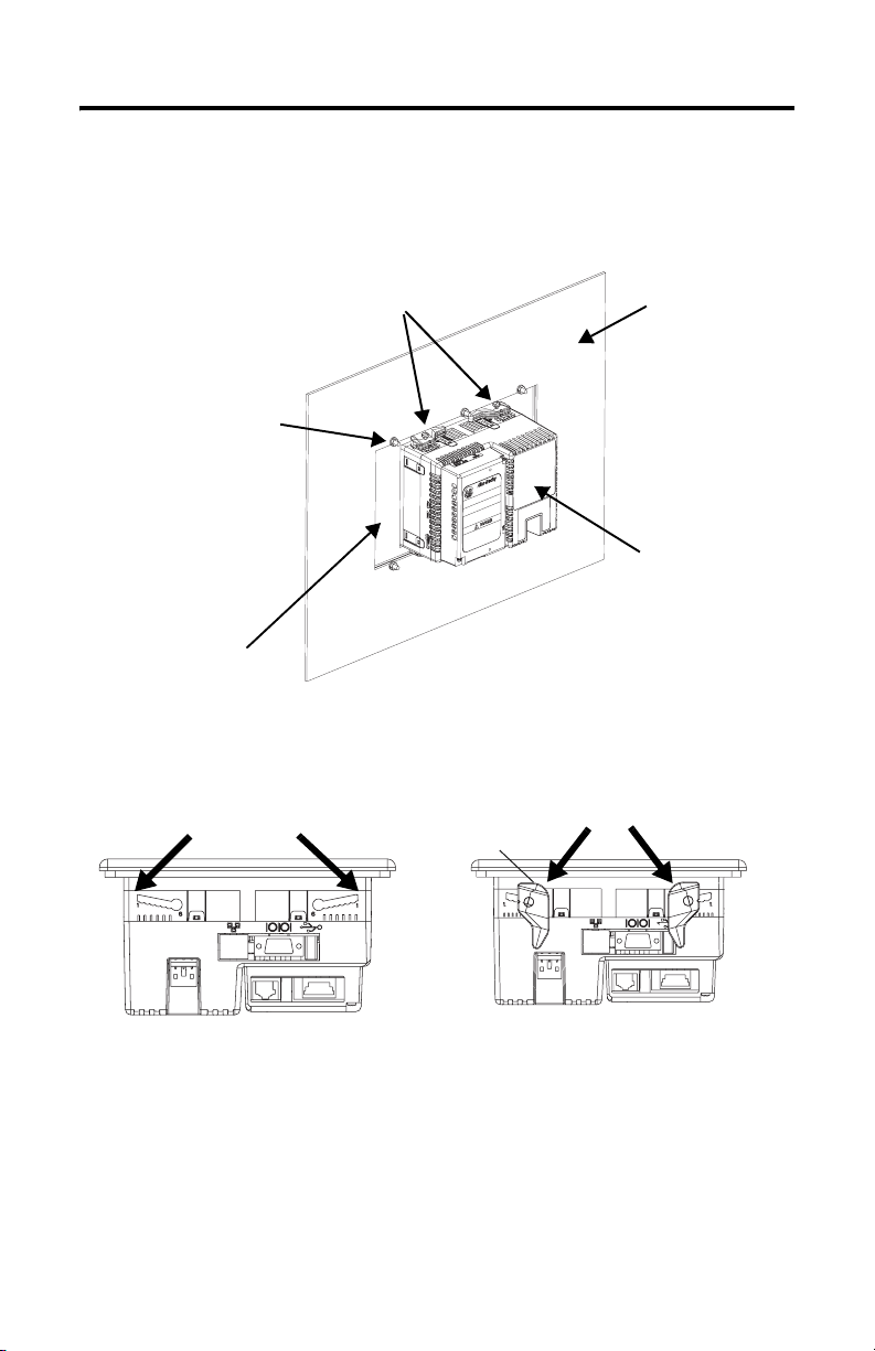
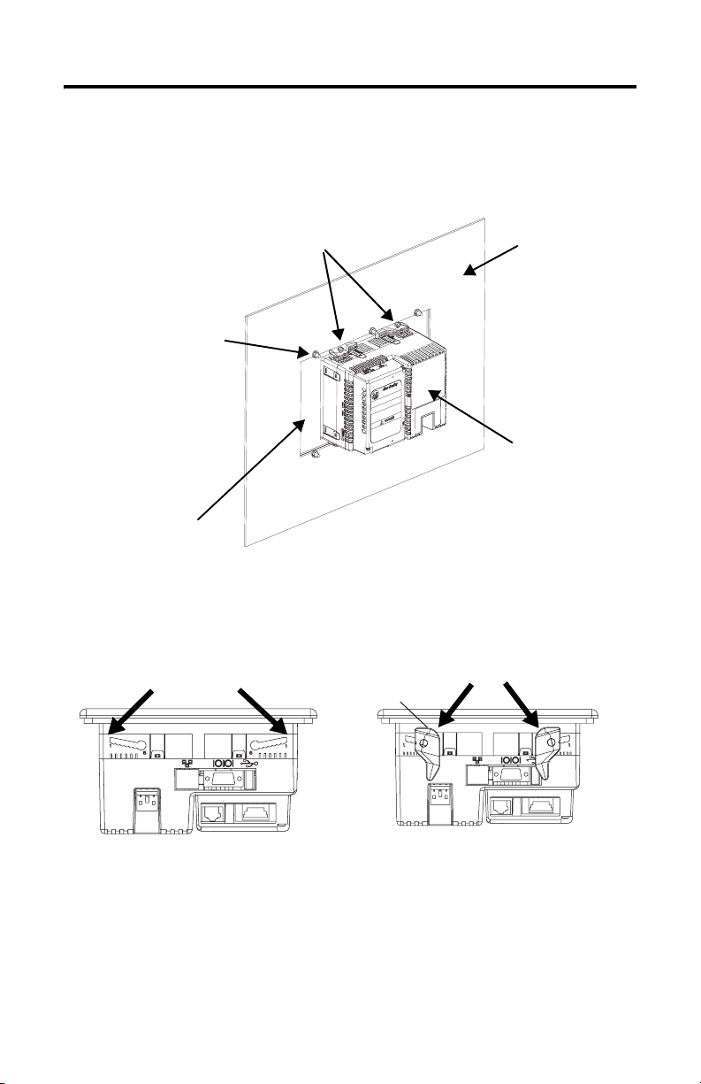
Attach Terminal to the Adapter Plate
1. Insert the new terminal into the front of the enclosure until the terminal gasket is
flush with the adapter plate.
Mounting Levers
Nut and Washer
Adapter Plate
Rear of Panel or
Enclosure
Rear of PanelView Plus
400 Keypad or 600
Touch Terminal
2. Insert 4 mounting levers into the mounting slots of the terminal (as shown below).
Slide each lever until flat side of lever touches the surface of the panel.
Mounting Slots
Flat Side of Lever
Mounting Lever
3. When all levers are in place, slide each lever an additional notch or two until you hear
a click.
Publication 2711P-IN020A-MU-P
Page 7
Cutout Adapter Kit 7
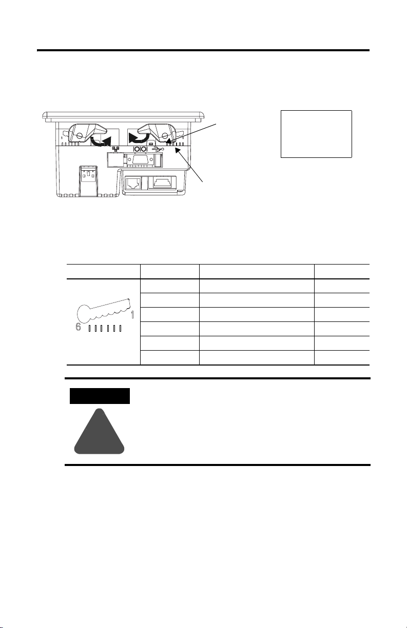
4. Rotate each lever in the direction indicated until lever is in final latch position. Follow
the latching sequence below to obtain optimum terminal fit.
14
4 Levers
3
2
Rotate until notch in levers
1
6
align with proper alignment
mark on terminal.
Alignment Marks
Notch
Use the table below as a guide to insure an adequate gasket seal between terminal and
panel.
Lever Position Panel Thickness Range Typical Gauge
1 0.15 - 2.01 mm (0.060 - 0.079 in) 16
1
2
3
4
5
6
Terminal Markings
for Alignment
ATTENTION
2 2.03 - 2.64 mm (0.08 - 0.104 in) 14
3 2.67 - 3.15 mm (0.105 - 0.124 in) 12
4 3.17 - 3.66 mm (0.125 - 0.144 in) 10
5 3.68 - 4.16 mm (0.145 - 0.164 in) 8/9
6 4.19 - 4.75 mm (0.165 - 0.187 in) 7
Follow instructions above to provide a proper seal and
to prevent potential damage to the terminal.
Allen-Bradley assumes no responsibility for water or
chemical damage to the terminal or other equipment
within the enclosure because of improper installation.
!
Publication 2711P-IN020A-MU-P
Page 8

8 Cutout Adapter Kit
Publication 2711P-IN020A-MU-P
Page 9

Notice d'installation
Kit d'adaptation de découpe
pour terminal PanelView Plus 400 à clavier et 600 dalle tactile
Référence 2711P-RAK4
Français
Description
Ce document indique comment monter un terminal PanelView Plus 400 à clavier ou un
terminal PanelView
PanelView
Standard 550 à clavier, à l'aide d'un kit d'adaptation.
Contenu du kit
Le kit d'adaptation pour découpe contient les éléments suivants :
• plaque d'adaptation pour découpe avec joint ;
• 6 écrous n° 8-32 avec rondelles frein.
Plus 600 à dalle tactile dans une découpe existante prévue pour un
Outils nécessaires
Les outils suivants sont nécessaires pour l'installation :
• une clé à douille avec douille de 11/32 pouce ;
• une clé dynamométrique permettant d'effectuer un serrage avec un couple de
Nm.
1,36
Publication 2711P-IN020A-MU-P
Page 10

10 Kit d'adaptation de découpe
Déconnexion du terminal
1. Déconnectez l'alimentation à la source et débranchez le cordon d'alimentation du
terminal PanelView.
2. Déconnectez tous les câbles de communication du terminal.
ATTENTION
Assurez-vous que le cordon d'alimentation du terminal
PanelView est déconnecté et que tous les autres câbles sont
déconnectés du terminal.
!
Retrait du terminal existant
1. Retirez les écrous autobloquants qui maintiennent le terminal sur le panneau.
2. Retirez le terminal du panneau.
Publication 2711P-IN020A-MU-P
Page 11
Kit d'adaptation de découpe 11
Fixation de la plaque d'adaptation sur le panneau
1. Alignez les goujons de la plaque d'adaptation sur les trous existants sur le panneau.
2. Placez la plaque d'adaptation dans la découpe du panneau de manière à bien
positionner le joint d'étanchéité contre l'avant du panneau.
Plaque
d'adaptation avant
Intérieur
du panneau
ou de l'armoire
Avant du panneau
ou de l'armoire
Ecrou et rondelle
3. Fixez la plaque d'adaptation sur les goujons à l'aide des écrous et des rondelles frein
fournis en les serrant jusqu'à ce que le joint d'étanchéité soit légèrement comprimé
contre le panneau.
4. Utilisez la clé dynamométrique pour serrer les écrous avec un couple d'1,36 Nm
maximum, afin de conserver une classification NEMA type
4X. Veillez à ne pas trop
serrer.
Publication 2711P-IN020A-MU-P
Page 12
12 Kit d'adaptation de découpe
Fixation du terminal à la plaque d'adaptation
1. Placez le nouveau terminal dans l'ouverture de manière à ce que son joint affleure la
plaque d'adaptation.
Attaches
de fixation
Ecrou et
rondelle
Plaque
d'adaptation
Arrière
du panneau
ou de l'armoire
Arrière du terminal
PanelView Plus 400 à
clavier ou un terminal
PanelView Plus 600 à
dalle tactile
2. Introduisez les 4 attaches de fixation dans les encoches situées sur le terminal (comme
illustré ci-dessous) et faites-les glisser jusqu'à que la partie plate des attaches soit en
contact avec la surface du panneau.
Encoches de
fixation
Partie plate
de l'attache
Attaches de fixation
3. Une fois toutes les attaches en place, faites-les glisser d'un ou deux crans
supplémentaires jusqu'à ce que vous entendiez un déclic.
Publication 2711P-IN020A-MU-P
Page 13

Kit d'adaptation de découpe 13
4. Faites-les ensuite pivoter dans la direction indiquée jusqu'à ce qu'elles soient
verrouillées. Suivez la séquence de verrouillage ci-dessous afin que votre terminal
soit maintenu le mieux possible.
14
4 attaches
3
2
Faites pivoter l'attache jusqu'à
ce que la petite encoche
1
6
située sur l'attache soit en
face du repère d'alignement
qui convient sur le terminal.
Repères
d'alignement
Encoche
Aidez-vous du tableau suivant pour assurer une bonne étanchéité du joint entre le
terminal et le panneau.
1
2
3
4
5
6
Repères d'alig nement
du terminal
ATTENTION
Position de
l'attache
1 0,1 - 2 mm 16
2 2 - 2,6 mm 14
3 2,6 - 3,1 mm 12
4 3,1 - 3,6 mm 10
5 3,6 - 4,1 mm 8/9
6 4,2 - 4,7 mm 7
Suivez les instructions ci-dessus pour assurer une bonne
étanchéité et éviter d'endommager le terminal. Allen-Bradley
Epaisseur du panneau Calibre type
ne saurait être tenu pour responsable des dégâts causés par
une infiltration d'eau ou de produit chimique dans le terminal
ou dans tout autre équipement présent dans l'armoire, suite à
!
une installation incorrecte.
Publication 2711P-IN020A-MU-P
Page 14

14 Kit d'adaptation de découpe
Publication 2711P-IN020A-MU-P
Page 15

Installationsanleitung
Adapter-Kit
für den Einbau von PanelView Plus 400-Terminals / 600-Terminal mit
Touchscreen
Bestellnummer 2711P-RAK4
Deutsch
Beschreibung
Das vorliegende Dokument erläutert, wie Sie ein PanelView Plus 400-Terminal mit Tastatur
oder ein PanelView Plus 600-Terminal mit Touchscreen mithilfe einer Adapterplatte in einen
vorhandenen Montageausschnitt für ein PanelView Standard 550-Terminal mit Tastatur
einbauen.
Lieferumfang
Das Adapter-Kit umfasst:
• Adapterplatte mit Dichtung für den Montageausschnitt
• 6 Muttern #8–32 mit flachen Sicherungsscheiben
Erforderliche Werkzeuge
Folgende Werkzeuge benötigen Sie zur Installation:
• Steckschlüssel mit 11/32-Zoll-Einsatz
• Drehmomentschlüssel für 1,36 N•m
Publikation 2711P-IN020A-MU-P
Page 16

16 Adapter-Kit
Unterbrechen der Stromversorgung zum Terminal
1. Unterbrechen Sie die Stromversorgung direkt an der Quelle und ziehen Sie das
Netzkabel vom PanelView-Terminal ab.
2. Ziehen Sie alle Kommunikationskabel vom Terminal ab.
ACHTUNG
Vergewissern Sie sich, dass das Netzkabel des
PanelView-Terminals sowie alle übrigen Kabel vom Terminal
abgezogen sind.
!
Ausbau des bestehenden Terminals
1. Entfernen Sie die selbstsichernden Muttern, mit denen das Terminal an der
Montageplatte befestigt ist.
2. Schieben Sie das vorhandene Terminal aus der Montageplatte heraus.
Publikation 2711P-IN020A-MU-P
Page 17

Adapter-Kit 17
Anbringen der Adapterplatte an der Montageplatte
1. Richten Sie die Stifte an der Adapterplatte mit den dafür in der Vorderseite der
Montageplatte vorgesehenen Montagelöcher aus.
2. Setzen Sie die Adapterplatte von vorne in den Montageausschnitt, bis die Dichtung
fest an der Vorderseite der Montageplatte anliegt.
Vordere
Adapterplatte
Innenseite der
Montageplatte
oder des Gehäuses
Vorderseite der Montageplatte
oder des Gehäuses
Mutter und Unterlegscheibe
3. Befestigen Sie die Adapterplatte, indem Sie die mitgelieferten Muttern und
Sicherungsscheiben mit den Stiften verschrauben, bis die Dichtung leicht an die
Vorderseite der Montageplatte angedrückt wird.
4. Verwenden Sie dazu einen Drehmomentschlüssel und ziehen Sie die Muttern mit
einem Drehmoment von nicht mehr als 1,36 N•m fest, um die Zulassung nach
NEMA Type 4X aufrechtzuerhalten. Achten Sie darauf, die Muttern nicht zu stark
anzuziehen.
Publikation 2711P-IN020A-MU-P
Page 18

18 Adapter-Kit
Anbringen des Terminals an der Adapterplatte
1. Setzen Sie das neue Terminal so in die Vorderseite des Gehäuses ein, dass die
Dichtung des Terminals bündig mit der Adapterplatte ist.
Montagehebel
Mutter und
Unterlegscheibe
Adapterplatte
Rückseite der
Montageplatte oder
des Gehäuses
Rückseite des
PanelView Plus
400-Terminals/
600-Terminal mit
Touchscreen
2. Führen Sie die 4 Montagehebel in die entsprechenden Montageschlitze auf dem
Terminal ein (siehe unten). Schieben Sie jeden Hebel in den Schlitzen so weit
vorwärts, bis die flache Seite des Hebels die Oberfläche der Montageplatte berührt.
Montageschlitze
Flache Seite des Hebels
Montagehebel
3. Wenn sich alle Hebel in der richtigen Position befinden, schieben Sie jeden Hebel um
eine oder zwei Kerben weiter, bis Sie ein Klicken hören.
Publikation 2711P-IN020A-MU-P
Page 19

Adapter-Kit 19
4. Drehen Sie jeden Hebel in die angegebene Richtung, bis sie sich in der endgültigen
Verriegelungsposition befinden. Halten Sie die nachfolgend dargestellte Reihenfolge
ein, um einen optimalen Sitz des Terminals zu erreichen.
14
4 Hebel
3
Drehen, bis die Kerbe in den
1
6
Hebeln mit der entsprechenden
Ausrichtungsmarkierung auf dem
Terminal übereinstimmt.
Ausrichtungsmarkierungen
Kerbe
Verwenden Sie die nachfolgende Tabelle als Richtlinie, um eine angemessene
Abdichtung zwischen Terminal und Montageplatte sicherzustellen.
1
2
3
4
5
6
Terminalmarkierungen
für die Ausrichtung
ACHTUNG
Hebelposition Stärke Montageplatte Typisches
1 0,15–2,01 mm 16
2 2,03–2,64 mm 14
3 2,67–3,15 mm 12
4 3,17–3,66 mm 10
5 3,68–4,16 mm 8/9
6 4,19–4,75 mm 7
Befolgen Sie die voranstehenden Anweisungen, um eine
ordnungsgemäße Abdichtung sicherzustellen und eine
Gauge-Maß
mögliche Beschädigung des Terminals zu vermeiden.
Rockwell Automation übernimmt keine Verantwortung für
Schäden durch Wasser oder Chemikalien am Terminal oder an
!
anderen Geräten innerhalb des Gehäuses, wenn diese durch
unsachgemäßen Einbau verursacht wurden.
2
Publikation 2711P-IN020A-MU-P
Page 20

20 Adapter-Kit
Publikation 2711P-IN020A-MU-P
Page 21

Istruzioni per l'installazione
Kit adattatore finestra
per terminale PanelView Plus 400 con Tastierino / 600 Touchscreen
Numero di catalogo 2711P-RAK4
Italiano
Descrizione
Questo documento descrive le istruzioni per il montaggio di un terminale PanelView Plus 400
con Tastierino o 600 Touchscreen su una finestra esistente per PanelView Standard 550 con
tastierino, utilizzando una piastra adattatrice.
Contenuto dell'imballo
Il kit adattatore per la finestra include:
• piastra adattatrice per la finestra con guarnizione
• 6 dadi num. 8-32 con rondelle di sicurezza
Strumenti richiesti
Per l'installazione sono richiesti i seguenti attrezzi:
• operatore per chiave a bussola da 11/32 di pollice
• chiave dinamometrica capace di 12 poll-lb. (1.36 N•m)
Pubblicazione 2711P-IN020A-MU-P
Page 22

22 Kit adattatore finestra
Scollegare il terminale
1. Scollegare l'alimentazione dalla sorgente e rimuovere il cavo di
alimentazione dal terminale PanelView.
2. Scollegare tutti i cavi di comunicazione dal terminale.
ATTENZIONE
Assicurarsi che il cavo di alimentazione e tutti gli altri
cavi del terminale PanelView siano stati scollegati.
!
Rimuovere il terminale esistente
1. Rimuovere i dadi autobloccanti che fissano il terminale al pannello.
2. Estrarre il terminale dal pannello.
Pubblicazione 2711P-IN020A-MU-P
Page 23

Kit adattatore finestra 23
Inserire la piastra adattatrice sul pannello
1. Allineare i perni della piastra adattatrice con gli appositi fori presenti sulla
parte frontale del pannello.
2. Inserire la piastra adattatrice sul frontale dell'apertura fino a quando la
guarnizione non risulti aderente al pannello.
Interno del pannello
o della custodia
Frontale del pannello o
della custodia
Frontale della
piastra adattatrice
Dado e rondella
3. Utilizzando i dadi e le rondelle di sicurezza forniti, avvitare la piastra fino a quando la
guarnizione non risulti leggermente compressa sul frontale del pannello.
4. Usando la chiave dinamometrica, stringere i dadi con una coppia non
superiore a 1.36 N•m (12
poll.-lb) per mantenere la classificazione NEMA
Tipo 4X. Non stringere troppo.
Pubblicazione 2711P-IN020A-MU-P
Page 24

24 Kit adattatore finestra
Inserire il terminale nella piastra adattatrice
1. Inserire il nuovo terminale sul frontale della custodia fino a quando la guarnizione del
terminale risulti allineata con la piastra adattatrice.
Levette di montaggio
Dado e rondella
Piastra adattatrice
Retro del pannello o
della custodia
Retro del terminale
PanelView Plus 400 con
Tastierino / 600
Touchscreen
2. Inserire le 4 levette di montaggio nelle apposite fessure del terminale (come mostrato
sotto). Fare scorrere ogni levetta fino a quando il lato piatto non tocchi la superficie
del pannello.
Fessure di montaggio
Lato piatto della levetta
Levetta di montaggio
3. Quando tutte le levette sono state inserite, spostarle di una o due tacche fino a quando
si sente un clic.
Pubblicazione 2711P-IN020A-MU-P
Page 25

Kit adattatore finestra 25
4. Ruotare le levette nella direzione indicata fino a portarle nella posizione finale di
blocco. Attenersi alla sequenza di chiusura indicata sotto per ottenere un blocco
ottimale del terminale.
14
4 Levette
3
2
Ruotare fino a quando la
1
6
tacca delle levette risulti in
linea con il segno di
allineamento del terminale.
Riferimenti per l'allineamento
Tac c a
Usare la tabella sottostante come guida per garantire un'adeguata tenuta tra terminale
e pannello.
2
3
4
5
6
Riferimenti del
terminale
ATTENZIONE
Posizione
levetta
1 0,15 - 2,01 mm 16
1
2 2,03 - 2,64 mm 14
3 2,67 - 3,15 mm 12
4 3,17 - 3,66 mm 10
5 3,68 - 4,16 mm 8/9
6 4,19 - 4,75 mm 7
Attenersi alle istruzioni descritte sopra per fornire una
tenuta corretta ed evitare potenziali danni al terminale.
Spessore pannello Calibro tipico
Allen-Bradley non è responsabile per eventuali danni al
terminale o ad altre apparecchiature all'interno della
custodia, provocati da acqua o agenti chimici e dovuti
!
ad un'installazione errata.
Pubblicazione 2711P-IN020A-MU-P
Page 26

26 Kit adattatore finestra
Pubblicazione 2711P-IN020A-MU-P
Page 27

Instrucciones de instalación
Kit de adaptador de corte
para terminal de teclado PanelView Plus 400/
pantalla táctil PanelView Plus 600
Número de catálogo 2711P-RAK4
Español
Descripción
Este documento proporciona instrucciones para montar un terminal de teclado PanelView
Plus 400 ó de pantalla táctil PanelView Plus 600 usando la placa adaptadora dentro del corte
existente para teclado PanelView estándar 550.
Contenido del paquete
El juego adaptador de corte incluye:
• placa adaptadora de corte con empaquetadura
• 6 tuercas #8-32 con arandelas de presión
Herramientas requeridas
Se requieren las siguientes herramientas para la instalación:
• llave de cubo con casquillo de 11/32 pulg.
• llave dinamométrica con capacidad para 12 pulg.-lb (1.36 N•m)
Publicación 2711P-IN020A-MU-P
Page 28

28 Kit de adaptador de corte
Desconecte el terminal
1. Desconecte la alimentación en la fuente y extraiga el cable de alimentación del
terminal PanelView.
2. Desconecte todos los cables de alimentación del terminal.
ATENCIÓN
Asegúrese de que el cable de alimentación del terminal
PanelView esté desconectado y que todos los cables hayan
sido desconectados del terminal.
!
Extraiga el terminal existente
1. Quite las tuercas de autotrabado que fijan el terminal al panel.
2. Deslice el terminal existente fuera del panel.
Publicación 2711P-IN020A-MU-P
Page 29

Kit de adaptador de corte 29
Acople la placa adaptadora al panel
1. Alinee los pernos en la placa adaptadora de corte con los orificios para pernos
existentes en la parte frontal del panel.
2. Coloque la placa adaptadora dentro de la parte frontal del corte de panel hasta que el
material de la empaquetadura selladora esté ubicado firmemente contra la parte
frontal del panel.
Placa adaptadora
frontal
Parte interior del
panel o
envolvente
Parte frontal del panel o envolvente
Tuerca y arandela
3. Con las tuercas con arandelas de presión suministradas, fije la placa de corte sobre los
pernos hasta que la empaquetadura selladora esté ligeramente comprimida contra la
parte frontal del panel.
4. Con la llave dinamométrica, apriete las tuercas a un par no mayor de 1.36 N•m
(12 pulg.-lb) para mantener la clasificación NEMA Tipo 4X. No las apriete
demasiado.
Publicación 2711P-IN020A-MU-P
Page 30

30 Kit de adaptador de corte
Acople el terminal a la placa adaptadora
1. Inserte el nuevo terminal en la parte frontal del envolvente hasta que la
empaquetadura del terminal quede al ras con la placa adaptadora.
Palancas de montaje
Tue rca y
arandela
Placa adaptadora
Parte trasera del
panel o
envolvente
Parte trasera del terminal
PanelView Plus 400/pantalla
táctil PanelView Plus 600
2. Inserte 4 palancas de montaje en las ranuras de montaje del terminal (como se
muestra a continuación). Deslice cada palanca hasta que el lado plano quede en
contacto con la superficie del panel.
Ranuras de montaje
Lado plano de la
palanca
Palanca de montaje
3. Una vez que las palancas estén ubicadas, deslice cada una de ellas una o dos muescas
más hasta que escuche un clic.
Publicación 2711P-IN020A-MU-P
Page 31

Kit de adaptador de corte 31
4. Gire cada palanca en la dirección indicada hasta que llegue a la posición de
enclavamiento final. Continúe con la secuencia de enclavamiento indicada a
continuación para obtener un ajuste óptimo del terminal.
14
4 palancas
3
2
Gire hasta que la muesca de
1
6
las palancas esté alineada
con la marca correcta de
alineación del terminal.
Marcas de
alineación
Muesca
Utilice la siguiente tabla como referencia para asegurar un sello de empaquetadura
adecuado entre el terminal y el panel.
1
2
3
4
5
6
Marcas del terminal
para alineación
Posición de la
palanca
1 0.15 – 2.01 mm
2 2.03 – 2.64 mm
3 2.67 – 3.15 mm
4 3.17 – 3.66 mm
5 3.68 – 4.16 mm
6 4.19 – 4.75 mm
Rango de grosor del panel Medidor
típico
16
(0.060 – 0.079 pulg.)
14
(0.08 – 0.104 pulg.)
12
(0.105 – 0.124 pulg.)
10
(0.125 – 0.144 pulg.)
8/9
(0.145 – 0.164 pulg.)
7
(0.165 – 0.187 pulg.)
ATENCIÓN
!
Siga las instrucciones previamente detalladas para lograr un
sellado adecuado y evitar un daño potencial del terminal.
Allen-Bradley no asumirá responsabilidad alguna por daños
ocasionados por agua o productos químicos al terminal u
otros equipos dentro del envolvente debido a una instalación
incorrecta.
Publicación 2711P-IN020A-MU-P
Page 32

32 Kit de adaptador de corte
Publicación 2711P-IN020A-MU-P
Page 33

Instruções de Instalação
Kit Adaptador de Corte
para Terminal PanelView Plus 400 Keypad / 600 Touch
Código de catálogo 2711P-RAK4
Português
Descrição
Este documento fornece instruções sobre como montar um terminal PanelView Plus 400
Keypad ou 600 Touch usando uma placa adaptadora em um corte de PanelView Standard 550
Keypad existente.
Conteúdo do pacote
O Kit Adaptador de Corte inclui:
• placa adaptadora de corte com junta
• 6 porcas #8-32 com arruelas de pressão
Ferramentas necessárias
As seguintes ferramentas são necessárias para a instalação:
• chave para soquete com soquete de 11/32 polegadas
• chave de torque com capacidade para 12 pol-lb (1,36 N•m)
Publicação 2711P-IN020A-MU-P
Page 34

34 Kit Adaptador de Corte
Desconecte o terminal
1. Desconecte a alimentação na fonte e remova o cabo de alimentação do terminal
PanelView.
2. Desconecte todos os cabos de comunicação do terminal.
ATENÇÃO
Certifique-se de que o cabo de alimentação do terminal
PanelView esteja desconectado e todos os cabos tenham sido
desconectados do terminal.
!
Remova o terminal existente
1. Remova as porcas de autotravamento que fixam o terminal ao painel.
2. Deslize o terminal existente para fora do painel.
Publicação 2711P-IN020A-MU-P
Page 35

Kit Adaptador de Corte 35
Fixe a placa adaptadora ao painel
1. Alinhe os pinos na placa adaptadora de corte aos furos dos pinos existentes na parte
frontal do painel.
2. Posicione a placa adaptadora na parte frontal do corte do painel até que o material da
junta de vedação esteja fixo firmemente na parte frontal do painel.
Placa adaptadora
frontal
Parte interna do
painel ou gabinete
Parte frontal do painel ou gabinete
Porca e arruela
3. Usando as porcas com as arruelas de pressão fornecidas, aperte a placa de corte nos
pinos até que a junta de vedação esteja ligeiramente comprimida contra a parte frontal
do painel.
4. Usando a chave de torque, aperte as porcas até no máximo 1,36 N•m (12 pol-lb) para
manter uma classificação NEMA Tipo 4X. Não aperte demais.
Publicação 2711P-IN020A-MU-P
Page 36

36 Kit Adaptador de Corte
Fixe o terminal à placa adaptadora
1. Insira o novo terminal na parte frontal do gabinete até que a junta do terminal esteja
rente à placa adaptadora.
Travas de instalação
Porca e arruela
Placa adaptadora
Parte traseira do
painel ou gabinete
Parte traseira do terminal
PanelView Plus 400 / 600
Touch
2. Insira as 4 travas de instalação nos slots do terminal (como exibido abaixo). Deslize
cada trava até que o lado plano toque a superfície do painel.
Slots de instalação
Lado plano da trava
Trava de instalação
3. Quando todas as travas estiverem posicionadas, deslize cada uma delas até um entalhe
ou dois a mais até que ouça um clique.
Publicação 2711P-IN020A-MU-P
Page 37

Kit Adaptador de Corte 37
4. Gire cada trava na direção indicada até que a trava esteja no ponto de retenção final.
Siga a seqüência de travamento abaixo para obter o melhor encaixe do terminal.
14
4 travas
3
2
Gire até que o entalhe nas
travas esteja alinhado com
1
6
a marca de alinhamento
adequada no terminal.
Entalhe
Marcas de alinhamento
Use a tabela abaixo como um guia para garantir uma vedação adequada da junta entre
o terminal e o painel.
1
2
3
4
5
6
Marcas de terminal
para alinhamento
ATENÇÃO
Posição da
trava
1 0,15 - 2,01 mm (0,060 - 0,079 pol.) 16
2 2,03 - 2,64 mm (0,08 - 0,104 pol.) 14
3 2,67 - 3,15 mm (0,105 - 0,124 pol.) 12
4 3,17 - 3,66 mm (0,125 - 0,144 pol.) 10
5 3,68 - 4,16 mm (0,145 - 0,164 pol.) 8/9
6 4,19 - 4,75 mm (0,165 - 0,187 pol.) 7
Siga as instruções acima para obter uma vedação adequada e
evitar possíveis danos ao terminal. A Allen-Bradley não se
Faixa de espessura do painel Bitola típica
responsabiliza por danos causados por água ou por produto
químico ao terminal ou a outro equipamento dentro do
gabinete devido à instalação incorreta.
!
Publicação 2711P-IN020A-MU-P
Page 38

38 Kit Adaptador de Corte
Publicação 2711P-IN020A-MU-P
Page 39

39
Publication 2711P-IN020A-MU-P
Page 40

Publication 2711P-IN020A-MU-P - November 2003 PN 41061-323-01(1)
Copyright © 2003 Rockwell Automation, Inc. A ll rights reserved. Printed in t he U.S.A.
 Loading...