

Page 1
Installation Instructions
Kinetix 6000M Hybrid Terminator
Catalog Number 2090-CTHP8
Topi c Page
Important User Information 2
Before You Begin 3
Installing the Hybrid Terminator 4
2090-CTHP8 Terminator Schematic and Pinout 5
Specifications 6
Additional Resources 6
About the Hybrid Terminator
A Kinetix® 6000M integrated drive-motor system shares DC bus and control power, system
status, and safety signals through a daisy-chain of hybrid cables between each integrated
drive-motor (IDM) in the drive system.
The 2090-CTHP8 hybrid terminator is a male M23 connector with a backshell cover that seals
the connector. The hybrid terminator is installed on the final IDM unit, as shown in the Kinetix
6000M Cable Routing Diagram diagram on page
returns the IDM system status signal to the IDM power interface module (IPIM).
2090-CTHP8 Hybrid Terminator
4. It terminates the communication bus and
Page 2
2 Kinetix 6000M Hybrid Terminator
Important User Information
Solid state equipment has operational characteristics differing from those of electromechanical equipment. Safety Guidelines for
the Application, Installation and Maintenance of Solid State Controls, publication SGI-1.1
Automation sales office or online at http://www.rockwellautomation.com/literature
between solid state equipment and hard-wired electromechanical devices. Because of this difference, and also because of the
wide variety of uses for solid state equipment, all persons responsible for applying this equipment must satisfy themselves that
each intended application of this equipment is acceptable.
In no event will Rockwell Automation, Inc. be responsible or li able for indirect or consequential damages resulting from the use or
application of this equipment.
The examples and diagrams in this manual are included solely for illustrative purposes. Because of the many variables and
requirements associated with any particular installation, Rockwell Automation, Inc. cannot assume responsibilit y or liability for
actual use based on the examples and diagrams.
No patent liability is assumed by Rockwell Automation, Inc. with respect to use of information, circuits, equipment, or software
described in this manual.
Reproduction of the contents of this manual, in whole or in part, without written permission of Rockwell Automation, Inc., is
prohibited.
Throughout this manual, when necessary, we use notes to make you aware of safety considerations.
WARNIN G: Identifies information about practices or circumstances that can cause an explosion in a
hazardous environment, which may lead to personal injury or death, property damage, or economic
loss.
, is available from your local Rockwell
) describes some important differences
ATTENTION: Identifies information about practices or circumstances that can lead to personal injury or
death, property damage, or economic loss. Attentions help you identify a hazard, avoid a hazard and
recognize the consequences.
SHOCK HAZARD: Labels may be on or inside the equipment, for example, drive or motor, to alert
people that dangerous voltage may be present.
BURN HAZARD: Labels may be on or inside the equipment, for example, drive or motor, to alert
people that surfaces may reach dangerous temperatures.
IMPORTANT Identifies information that is critical for successful application and understanding of the product.
Publication 2090-IN035B-EN-P - March 2012
Page 3
Kinetix 6000M Hybrid Terminator 3
Before You Begin
Remove all packing material from within and around the item. After unpacking, verify the
catalog number against the purchase order, and visually inspect the cable and each connector for
damage. If necessary, immediately notify the carrier of any shipping damage.
Observe the following precautions when installing the connector in a servo system. Failure to
observe these safety notices could result in personal injury or damage to the motor and
equipment.
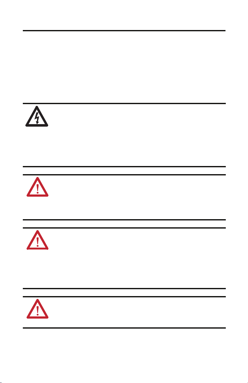
SHOCK HAZARD: To avoid the hazard of electrical shock, be sure to ground any cable providing
power at a minimum of one point. To prevent the build-up of electrical energy, factory-supplied
power cables use one of these grounding techniques:
• Bond the overall shield to the connector housing.
• Make sure there is a direct connec tion-to-ground for each hybrid cable shield.
• Connect an exposed cable braid or a ground wire, if present, to the power cable clamp,
housing, or another suitable chassis ground.
Failure to observe these safety procedures could result in personal injury or equipment damage.
ATT EN TI ON : Arcing or unexpected motion can occur if cables are connected or disconnected while
power is applied to the IDM sy stem. Before working on an IDM system, disconnect power and wait
the full time interval as indicated in the warning on the IPIM module or verify the DC bus voltage at
the IPIM module measures less than 50V DC.
Failure to observe this precaution could result in severe bodily injury or loss of life, and damage to
the product will occur.
ATTENTION: The hybrid connectors are designed to be rotated into a fixed position during motor
installation, and remain in that position without further adjustment. Strictly limit the applied
forces and the number of times the hybrid connectors are rotated to make sure the connectors
meet the specified IP ratings.
Apply force only to the connector and cable plug. Do not apply force to the cable extending from
the cable plug. No tools, for example pliers or vise-grips, should be used to assist with the rotation
of the connector.
Failure to observe safety precautions could result in damage to the IDM unit and its components.
ATT EN TI ON : The overall shield on the hybrid cable must be grounded to obtain effective shielding
for optimum performance.
Be sure there is an effective connection between any hybrid cable shields and the Kinetix 6000M
system ground.
Publication 2090-IN035B-EN-P - March 2012
Page 4
4 Kinetix 6000M Hybrid Terminator
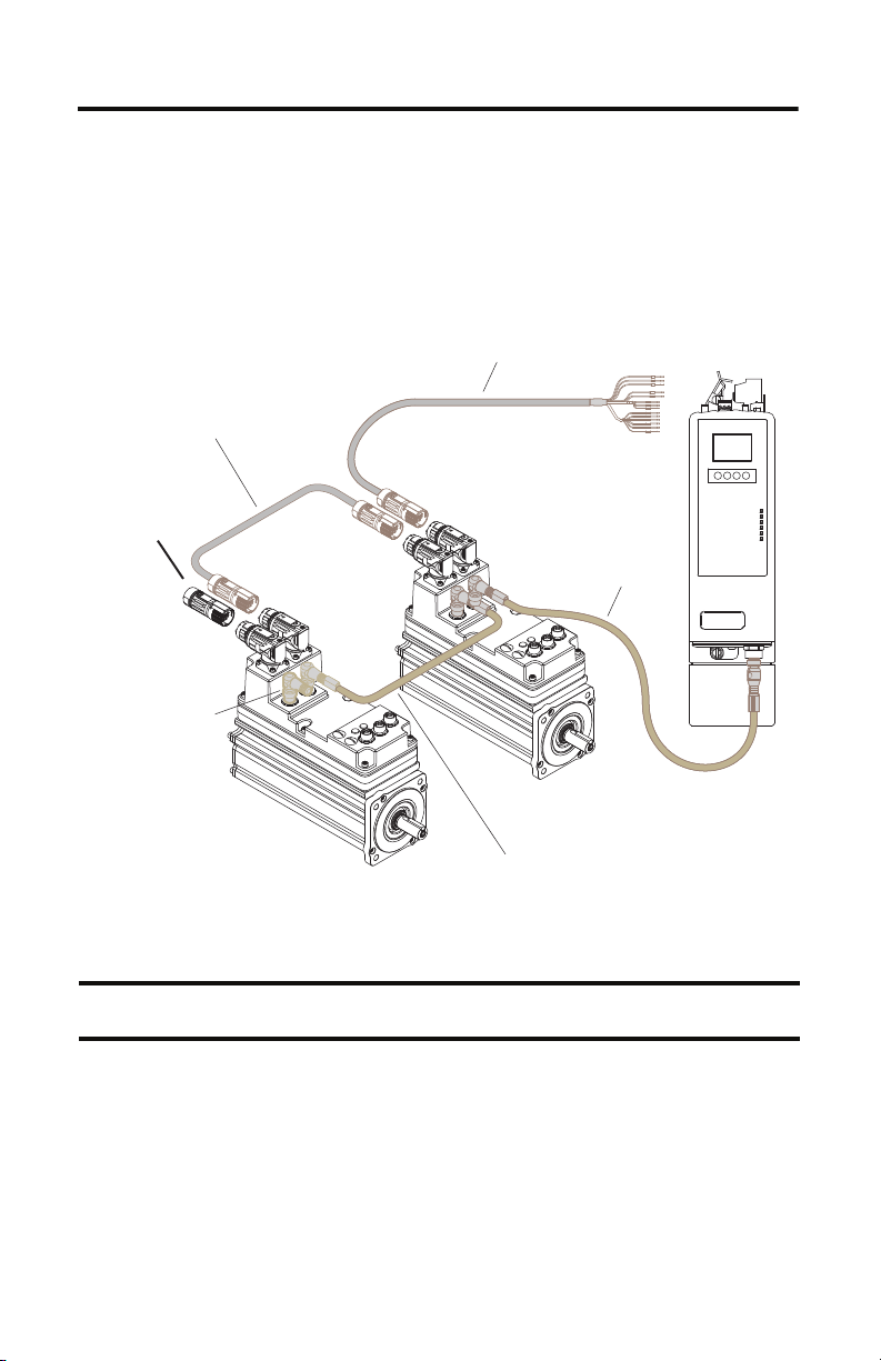
IMPORTANT
PORT 1 PORT 2 NETWORK
R
R
G
G
R
R
G
G
2094-SEPM-B24-S
IPIM Module
2090-CHBIFS8-12AAxx
IPIM-to-IDM Hybrid Cable
Connects the IPIM Module to the First IDM Unit
2090-CHBP8S8-12AA
x
Hybrid Cable
2090-CTHP8
Hybrid Terminator
MDF-SB1
xxx
Last IDM Unit
2090-CTSRP
Network Terminator
2090-CNSSPSS-12AAxx
or 2090-CNSSPRS-AAxx
Network Cable
2090-CNSSPSS-AAxx (shown), 2090-CNSRPRS-AAxx,
2090-CNSSPRS-AAxx, or 2090-CNSRPSS-AAxx
Network Cable
MDF-SB1xxx
First ID M Unit
Installing the Hybrid Terminator
Follow these steps when installing the 2090-CTHP8 hybrid terminator.
Kinetix 6000M Cable Routing Diagram
Publication 2090-IN035B-EN-P - March 2012
The colored rings on the hybrid output connector and the terminator must match:
green-to-green.
Page 5

Kinetix 6000M Hybrid Terminator 5
IMPORTANT
Male Plug
100 Ω
CN+
CN -
SYS OK +
SYS OK -
1. Verify power to the IPIM module is removed before making any connections or
disconnecting any components of the system.
ATT EN TI ON : Arcing or unexpected motion can occur if cables are connected or disconnected while
power is applied to the IDM sy stem. Before working on an IDM system, disconnect power and wait
the full time interval as indicated in the warning on the IPIM module or verify the DC bus voltage at
the IPIM module measures less than 50V DC.
Failure to observe this precaution could result in severe bodily injury or loss of life, and damage to
the product will occur.
2. Attach the hybrid terminator to the power-out connector on the last IDM unit in the
system.
3. Tighten the M23 connector approximately 45° to fully seat the contacts and secure the
connection.
The internal O-ring is self-conforming and requires a short period between each
connect/disconnect cycle to expand to full size. Allow at least one minute for the O-ring to
expand before reconnecting the hybrid terminator.
2090-CTHP8 Terminator Schematic and Pinout
A
B
C
D
GND
1
2
3
4
5
6
7
8
9
10
GND
4
98710
5
6
BC
2
1
3
DA
Publication 2090-IN035B-EN-P - March 2012
Page 6

6 Kinetix 6000M Hybrid Terminator
Specifications
Additional specifications for each cable are available in the Kinetix Motion Control Accessories
Technical Data, publication GMC-TD004.
Attribute 2090-CTHP8
Wire s ize 22 AWG
Additional Resources
These documents contain additional information concerning related products from Rockwell
Automation.
Resource Description
Integrated Drive-Motor User Manual, publications 2094-UM003
Kinetix 6000M Integrated D rive-Motor System Power Interface
Module (IPIM) Installation Instructions 2094-IN016
Kinetix 6000M Integrated Drive-Motor Installation Instructions
MDF-IN001
Allen-Bradley Industrial Automation Glossary, publication
AG-7. 1
System Design for Control of Electrical Noise Reference Manual,
publication GMC-RM001
Kinetix Rotary Motion Specifications Technical Data,
publication GMC-TD001
Kinetix Motion Control Accessories Technical Data,
publication GMC-TD004
Kinetix Motion Control Selection Guide,
publication GMC-SG001
Information on installing, configuring, starting up, and
troubleshooting a servo drive system with a servo motor.
Information on the installation of your Kinetix 6000M
IDM Power Interface Module.
Information on the installation of your Kinetix 6000M
integrated drive-motor.
A glossary of industrial automation terms and abbreviations.
Information, examples, and techniques designed to minimize
system failures caused by electrical noise.
Catalog numbers and product specifications, including
performance, environmental, certifications, load force, and
dimension drawings for Allen-Bradley rotary motors.
Catalog numbers, specifications, and dimensions for
Allen-Bradley servo drive accessories.
General product specifications for Kinetix motion control
products.
You can view or download publications at http://www.rockwellautomation.com/literature
To order paper copies of technical documentation, contact your Allen-Bradley distributor or
Rockwell Automation sales representative.
Publication 2090-IN035B-EN-P - March 2012
.
Page 7

Notes:
Kinetix 6000M Hybrid Terminator 7
Publication 2090-IN035B-EN-P - March 2012
Page 8

Rockwell Automation Support
Rockwell Automation provides tec hnical information on the Web to assist you in using its products.
At http://www.rockwellautomation.com/support
links to software service packs, and a MySupport feature that you can customize to make the best use of these tools. You can also visit
our Knowledgebase at http://www.rockwellautomation.com/knowledgebase
forums, software updates, and to sign up for product notification updates.
For an additional level of technical phone support for installation, configuration and troubleshooting, we offer TechConnect support
programs. For more information, contact your local distributor or Rockwell Automation representative, or visit
http://www.rockwellautomation.com/support/
Installation Assistance
If you experience a problem within the first 24 hours of installation, please review the information that's contained in this manual.
You can also contact a special Customer Support number for initial help in getting your product up and running.
United States or Canada 1.440.646.3434
Outside United States or
Canada
Use the Wor ldwi de Loc ator
http://www.rockwellautomation.com/support/americas/phone_en.html
Rockwell Automation representative.
New Product Satisfaction Return
Rockwell Automation tests all o f its products to ensure that they are fully operational when shipped from the manufacturing facility.
However, if your product is not functioning and needs to be returned, follow these procedures.
, you can find technical manuals, technical and application notes, sample code and
for FAQs, technical information, support chat and
.
at
, or contact your local
United States
Outside United States Please contact your local Rockwell Automation representative for the return procedure.
Contact your distributor. You must provide a Customer Support case number (call the phone number
above to obtain one) to your distributor to complete the return process.
Documentation Feedback
Your comments will help us serve your documentation needs better. If you have any suggestions on how to improve this document,
complete this form, publication RA-DU002
Allen-Bradley, Kinetix, Rockwell Software, Rockwell Automation, and TechConnect are trademarks of Rockwell Automation, Inc.
Trademarks not belonging to Rockwell Automation are property of their respective companies.
Rockwell Otomasyon Ticaret A.Ş., Kar Plaza İş Merkezi E Blok Kat:6 34752 İçerenköy, İstanbul, Tel: +90 (216) 5698400
Publication 2090-IN035B-EN-P - March 2012 PN-143960
Supersedes Publication 2090-IN035A-EN-P - February 2012 Copyright © 2012 Rockwell Automation, Inc. All rights reserved. Printed in the U.S.A.
, available at http://www.rockwellautomation.com/literature/.
 Loading...